Page 868 of 5267
P2509-POWERDOWN DATA LOST ERROR
For a complete wiring diagramRefer to Section 8W.
Page 869 of 5267

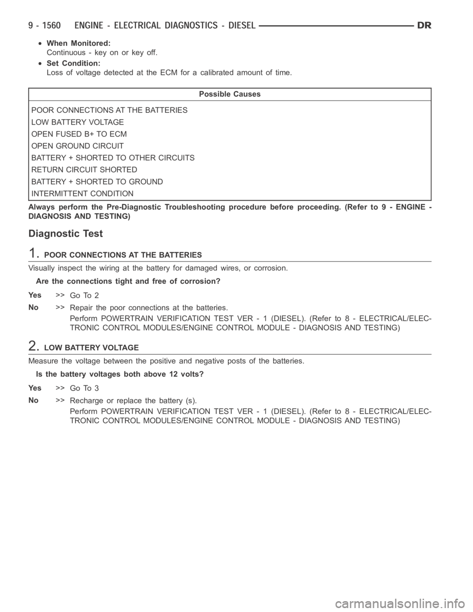
When Monitored:
Continuous - key on or key off.
Set Condition:
Loss of voltage detected at the ECM for a calibrated amount of time.
Possible Causes
POOR CONNECTIONS AT THE BATTERIES
LOW BATTERY VOLTAGE
OPEN FUSED B+ TO ECM
OPEN GROUND CIRCUIT
BATTERY + SHORTED TO OTHER CIRCUITS
RETURN CIRCUIT SHORTED
BATTERY + SHORTED TO GROUND
INTERMITTENT CONDITION
Always perform the Pre-Diagnostic Troubleshooting procedure before proceeding. (Refer to 9 - ENGINE -
DIAGNOSIS AND TESTING)
Diagnostic Test
1.POOR CONNECTIONS AT THE BATTERIES
Visually inspect the wiring at the battery for damaged wires, or corrosion.
Are the connections tight and free of corrosion?
Ye s>>
Go To 2
No>>
Repair the poor connections at the batteries.
Perform POWERTRAIN VERIFICATION TEST VER - 1 (DIESEL). (Refer to 8 - ELECTRICAL/ELEC-
TRONIC CONTROL MODULES/ENGINE CONTROL MODULE - DIAGNOSIS AND TESTING)
2.L O W B AT T E RY V O LTA G E
Measure the voltage between the positive and negative posts of the batteries.
Is the battery voltages both above 12 volts?
Ye s>>
Go To 3
No>>
Recharge or replace the battery (s).
Perform POWERTRAIN VERIFICATION TEST VER - 1 (DIESEL). (Refer to 8 - ELECTRICAL/ELEC-
TRONIC CONTROL MODULES/ENGINE CONTROL MODULE - DIAGNOSIS AND TESTING)
Page 872 of 5267
P2607-LOW VOLTAGE AT THE #2 INTAKE AIR HEATER RELAY
For a complete wiring diagramRefer to Section 8W.
Page 873 of 5267

When Monitored:
When the ignition is on.
Set Condition:
When the signal from the #2 intake air heater output does not match the signal from the #2 intake air heater
feedback.
Possible Causes
LOOSE CONNECTION
INTAKEAIRHEATERRELAY
SIGNAL CIRCUIT OPEN FROM RELAY TO ECM
SIGNAL CIRCUIT SHORTED TO BATTERY NEGATIVE
ECM
INTERMITTENT CONDITION
Always perform the Pre-Diagnostic Troubleshooting procedure before proceeding. (Refer to 9 - ENGINE -
DIAGNOSIS AND TESTING)
Diagnostic Test
1.RELAY CLICKING
Ignition on, engine not running.
With the scan tool, actuate the #1 Intake Air Heater.
Can you hear the Relay clicking?
Ye s>>
Go To 2
No>>
Go To 3
2.LOOSE CONNECTION
While the relay is clicking , wiggle the wiring harness and connectors.
Does this interrupt the clicking?
Ye s>>
Repair the poor connection.
Perform POWERTRAIN VERIFICATION TEST VER - 1 (DIESEL). (Refer to 8 - ELECTRICAL/ELEC-
TRONIC CONTROL MODULES/ENGINE CONTROL MODULE - DIAGNOSIS AND TESTING)
No>>
Go To 3
3.INTAKE AIR HEATER RELAY
Turn the ignition off.
Remove the Intake Air Heater #1 Relay.
Check connectors - Clean/repair as necessary.
Measure the resistance between the signal and return posts of the intake air heater relay.
Is the resistance between 15 and 25 Ohms?
Ye s>>
Go To 4
No>>
Replace the Intake Air Heater #1 relay.
Perform POWERTRAIN VERIFICATION TEST VER - 1 (DIESEL). (Refer to 8 - ELECTRICAL/ELEC-
TRONIC CONTROL MODULES/ENGINE CONTROL MODULE - DIAGNOSIS AND TESTING)
Page 875 of 5267
P2608-HIGH VOLTAGE AT THE #2 INTAKE AIR HEATER RELAY
For a complete wiring diagramRefer to Section 8W.
Page 876 of 5267

When Monitored:
When the ignition is on.
Set Condition:
When the signal from the #2 Intake Air Heater output does not match the signal from the #2 Intake Air Heater
feedback.
Possible Causes
LOOSE CONNECTION
INTAKEAIRHEATERRELAY
SIGNAL CIRCUIT SHORTED TO BATTERY NEGATIVE
ECM
INTERMITTENT CONDITION
Always perform the Pre-Diagnostic Troubleshooting procedure before proceeding. (Refer to 9 - ENGINE -
DIAGNOSIS AND TESTING)
Diagnostic Test
1.RELAY CLICKING
Ignition on, engine not running.
With the scan tool, actuate the Intake Air Heater relay.
Can you hear the Relay clicking?
Ye s>>
Go To 2
No>>
Go To 3
2.LOOSE CONNECTION
While the relay is clicking , wiggle the wiring harness and connectors.
Does this interrupt the clicking?
Ye s>>
Repair the poor connection.
Perform POWERTRAIN VERIFICATION TEST VER - 1 (DIESEL). (Refer to 8 - ELECTRICAL/ELEC-
TRONIC CONTROL MODULES/ENGINE CONTROL MODULE - DIAGNOSIS AND TESTING)
No>>
Go To 3
3.INTAKE AIR HEATER RELAY
Turn the ignition off.
Remove the Intake Air Heater Relay.
Check connectors - Clean/repair as necessary.
Measure the resistance between the signal and return posts of the intake air heater relay.
Is the resistance between 15 and 25 Ohms?
Ye s>>
Go To 4
No>>
Replace the Intake Air Heater relay.
Perform POWERTRAIN VERIFICATION TEST VER - 1 (DIESEL). (Refer to 8 - ELECTRICAL/ELEC-
TRONIC CONTROL MODULES/ENGINE CONTROL MODULE - DIAGNOSIS AND TESTING)
Page 878 of 5267
P2609-NO VOLTAGE DROP SEEN FROM INTAKE AIR HEATERS
For a complete wiring diagramRefer to Section 8W.
Page 881 of 5267

*CHECKING THE ACCELERATOR PEDAL SENSOR CALIBRATION
Possible Causes
MIS-WIRED APPS
VOLTAGE NOT CHANGING DURING SWEEP
THROTTLE PEDAL NOT MOVING FREELY
APPS
Diagnostic Test
1.MIS-WIRED APPS
Turn the ignition off.
Remove the APPS cover.
Inspect both APPS connector and ECM for proper wiring.
Are both connectors wired correctly?
Ye s>>
Go To 2
No>>
Repair mis-wired APPS connector at APPS or ECM.
Perform POWERTRAIN VERIFICATION TEST VER - 1 (DIESEL). (Refer to 8 - ELECTRICAL/ELEC-
TRONIC CONTROL MODULES/ENGINE CONTROL MODULE - DIAGNOSIS AND TESTING)
2.THROTTLE PEDAL NOT MOVING FREELY
Ignition on, engine not running.
Look for proper Throttle operation.
Does the Throttle Pedal move freely between the upper and lower stops?
Ye s>>
Replace the APPS.
Perform POWERTRAIN VERIFICATION TEST VER - 1 (DIESEL). (Refer to 8 - ELECTRICAL/ELEC-
TRONIC CONTROL MODULES/ENGINE CONTROL MODULE - DIAGNOSIS AND TESTING)
No>>
Repair as necessary.
Perform POWERTRAIN VERIFICATION TEST VER - 1 (DIESEL). (Refer to 8 - ELECTRICAL/ELEC-
TRONIC CONTROL MODULES/ENGINE CONTROL MODULE - DIAGNOSIS AND TESTING)