2006 DODGE RAM SRT-10 oil pressure
[x] Cancel search: oil pressurePage 3302 of 5267
7.CHECK IF THE DTC P0871 ALSO SET
With the scan tool, check Transmission DTCs.
Is the DTC P0871 also present?
Ye s>>
Refer to the Transmission category and perform the appropriate symptom.
No>>
Go To 8
8.CHECK IF THE DTC SET IN PARK, REVERSE OR NEUTRAL
With the scan tool, check the DTC EVENT DATA for P0988.
NOTE: Make sure to record all DTC EVENT DATA stored in the scan tool for future reference in this test
procedure.
Does the DTC EVENT DATA show the DTC set in Park, Neutral, or Reverse for P0988?
Ye s>>
Go To 13
No>>
Go To 9
9.CHECK IF THE DTC EVENT DATA READS CLOSED
With the scan tool, check the DTC EVENT DATA for P0988.
NOTE: Make sure to record all DTC EVENT DATA stored in the scan tool for future reference in this test
procedure.
Does the DTC EVENT DATA show the 4C Pressure Switch reading CLOSED?
Ye s>>
Go To 11
No>>
Go To 10
10.CHECK THE PRIMARY OIL FILTER SEAL
In the DTC EVENT DATA recorded earlier,compare the Line Pressure and the Desired Line Pressure.
Is the Line Pressure less than 40 psi, and significantly below the Desired Line Pressure?
Ye s>>
Repair as necessary to correct low line pressure. Check fluid level and adjustasnecessary.Iffluidlevel
is OK, check the Primary Oil Filter seal for a split, crack, or improperly installed. If the filter and seal are
OK, check the Main Regulator Valve in the Oil Pump. Refer to the Service Information for the above
procedures.
Perform 45RFE/545RFE TRANSMISSION VERIFICATION TEST - VER 1. (Refer to 21- TRANSMIS-
SION/TRANSAXLE/AUTOMATIC - 45RFE/545RFE - STANDARD PROCEDURE)
No>>
Go To 15
11 .CHECK THE PCM AND WIRING
Turn the ignition off to the lock position.
Remove the Ignition Switch Feed fuse from the TIPM.
CAUTION: Removal of the Ignition Switch Feed fuse from the TIPM will prevent the vehicle from being
startedingear.
WARNING: The Ignition Switch Feed fuse must be removed from the TIPM. Failure to do so can result in
personal injury or death.
Install the Transmission Simulator, Miller tool #8333.
Ignition on, engine not running.
With the Transmission Simulator, turn the Pressure Switch selector switchtothe4Cposition.
Page 3304 of 5267
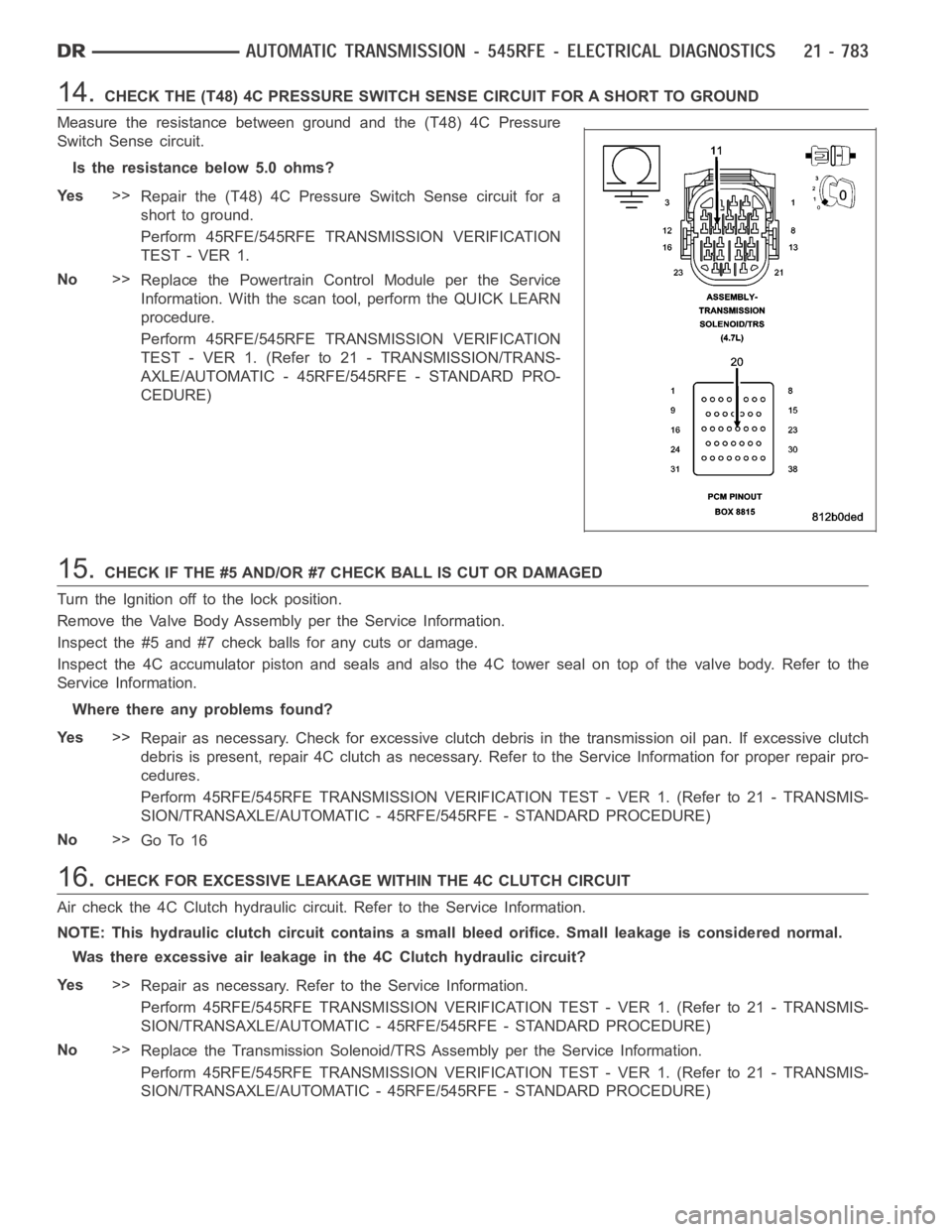
14.CHECK THE (T48) 4C PRESSURE SWITCH SENSE CIRCUIT FOR A SHORT TO GROUND
Measure the resistance between ground and the (T48) 4C Pressure
Switch Sense circuit.
Is the resistance below 5.0 ohms?
Ye s>>
Repair the (T48) 4C Pressure Switch Sense circuit for a
short to ground.
Perform 45RFE/545RFE TRANSMISSION VERIFICATION
TEST - VER 1.
No>>
Replace the Powertrain Control Module per the Service
Information. With the scan tool, perform the QUICK LEARN
procedure.
Perform 45RFE/545RFE TRANSMISSION VERIFICATION
TEST - VER 1. (Refer to 21 - TRANSMISSION/TRANS-
AXLE/AUTOMATIC - 45RFE/545RFE - STANDARD PRO-
CEDURE)
15.CHECK IF THE #5 AND/OR #7 CHECK BALL IS CUT OR DAMAGED
Turn the Ignition off to the lock position.
Remove the Valve Body Assembly per the Service Information.
Inspect the #5 and #7 check balls for any cuts or damage.
Inspect the 4C accumulator piston and seals and also the 4C tower seal on topof the valve body. Refer to the
Service Information.
Where there any problems found?
Ye s>>
Repair as necessary. Check for excessive clutch debris in the transmission oil pan. If excessive clutch
debris is present, repair 4C clutch as necessary. Refer to the Service Information for proper repair pro-
cedures.
Perform 45RFE/545RFE TRANSMISSION VERIFICATION TEST - VER 1. (Refer to 21- TRANSMIS-
SION/TRANSAXLE/AUTOMATIC - 45RFE/545RFE - STANDARD PROCEDURE)
No>>
Go To 16
16.CHECK FOR EXCESSIVE LEAKAGE WITHIN THE 4C CLUTCH CIRCUIT
Air check the 4C Clutch hydraulic circuit. Refer to the Service Information.
NOTE: This hydraulic clutch circuit contains a small bleed orifice. Smallleakage is considered normal.
Was there excessive air leakage in the 4C Clutch hydraulic circuit?
Ye s>>
Repair as necessary. Refer to the Service Information.
Perform 45RFE/545RFE TRANSMISSION VERIFICATION TEST - VER 1. (Refer to 21- TRANSMIS-
SION/TRANSAXLE/AUTOMATIC - 45RFE/545RFE - STANDARD PROCEDURE)
No>>
Replace the Transmission Solenoid/TRS Assembly per the Service Information.
Perform 45RFE/545RFE TRANSMISSION VERIFICATION TEST - VER 1. (Refer to 21- TRANSMIS-
SION/TRANSAXLE/AUTOMATIC - 45RFE/545RFE - STANDARD PROCEDURE)
Page 3322 of 5267

Diagnostic Test
1.DETERMINING IF RELATED DTC’S ARE PRESENT
With the scan tool, check for other transmission DTCs.
Are any Transmission: solenoid, line pressure, speed sensor, or loss of primeDTCspresent?
Ye s>>
Refer to appropriate symptom in the Transmission category. Perform the test for P0944-LOSS OF
PRIME first if it is present.
No>>
Go To 2
2.CHECK DTC EVENT DATA
With the scan tool, read and record the DTC EVENT DATA.
NOTE: Make sure to record all DTC EVENT DATA stored in the scan tool for future reference in this test
procedure.
Does the DTC EVENT DATA display information for the DTC P1736?
Ye s>>
Go To 3
No>>
Go To 6
3.CHECK RPM IN DTC EVENT DATA
Refer to the DTC EVENT DATA recorded earlier.
Does the Input RPM read zero?
Ye s>>
Check the input speed sensor and wiring. Refer to test P0715 and diagnose asif the DTC is current.
No>>
Go To 4
4.CHECK LINE PRESSURE READING
Refer to the DTC EVENT DATA recorded earlier.
Isthelinepressurereadingmorethan10 psi below the desired line pressure?
Ye s>>
Go To 5
No>>
Go To 6
5.PLUGGED TRANSMISSION OIL FILTER
Turn the ignition off to the lock position.
Remove and inspect the Transmission Oil Pan for excessive debris per the Service Information.
Remove and inspect the Primary Oil Filter per the Service Information.
NOTE: Make sure the Primary Transmission Oil Filter and/or seal is not cracked or split.
Does the Oil Pan contain excessive debris and/or is the Primary Oil Filter cracked or plugged?
Ye s>>
Repair the plugged, cracked, or split Primary Transmission Oil Filter and/or seal. If the Primary Trans-
mission Oil Filter is plugged, refer to the Service Information for the proper hydraulic clutch repair pro-
cedure.
Perform 45RFE/545RFE TRANSMISSION VERIFICATION TEST - VER 1. (Refer to 21- TRANSMIS-
SION/TRANSAXLE/AUTOMATIC - 45RFE/545RFE - STANDARD PROCEDURE)
No>>
Remove the Transmission Oil Pump per the Service Information. Check the main Regulator Valve for
sticking in its bore, scoring, and/or damage and clean and repair as necessary. If no problem is found,
replace the Transmission Solenoid/TRS Assembly.
Perform 45RFE/545RFE TRANSMISSION VERIFICATION TEST - VER 1. (Refer to 21- TRANSMIS-
SION/TRANSAXLE/AUTOMATIC - 45RFE/545RFE - STANDARD PROCEDURE)
Page 3328 of 5267
3.CHECK THE PCM AND WIRING
Turn the ignition off to the lock position.
Remove the Ignition Switch Feed fuse from the TIPM.
CAUTION: Removal of the Ignition Switch Feed fuse from the TIPM will prevent the vehicle from being
startedingear.
WARNING: The Ignition Switch Feed fuse must be removed from the TIPM. Failure to do so can result in
personal injury or death.
Install the Transmission Simulator, Miller tool #8333.
Ignition on, engine not running.
With the Transmission Simulator, turn the Pressure Switch selector switchtoL/R.
With the scan tool, monitor the L/R Pressure Switch state while pressing thePressureSwitchTestbuttononthe
Transmission Simulator.
Did the state of the L/R Pressure Switch change while pressing the PressureSwitch Test button?
Ye s>>
Go To 4
No>>
Go To 5
4.CHECK IF THE SOLENOID SWITCH VALVE STICKING
Turn the ignition off to the lock position.
Remove the Transmission Oil Pan per the Service Information.
Remove the Transmission Valve body per the Service Information.
Inspect the Solenoid Switch Valve and Plugs for sticking.
Is the Solenoid Switch Valve or Plugs sticking?
Ye s>>
Clean and inspect per the Service Information. Repair as necessary.
Perform 45RFE/545RFE TRANSMISSION VERIFICATION TEST - VER 1. (Refer to 21- TRANSMIS-
SION/TRANSAXLE/AUTOMATIC - 45RFE/545RFE - STANDARD PROCEDURE)
No>>
Replace the Transmission Solenoid/TRS Assembly per the Service Information.
Perform 45RFE/545RFE TRANSMISSION VERIFICATION TEST - VER 1. (Refer to 21- TRANSMIS-
SION/TRANSAXLE/AUTOMATIC - 45RFE/545RFE - STANDARD PROCEDURE)
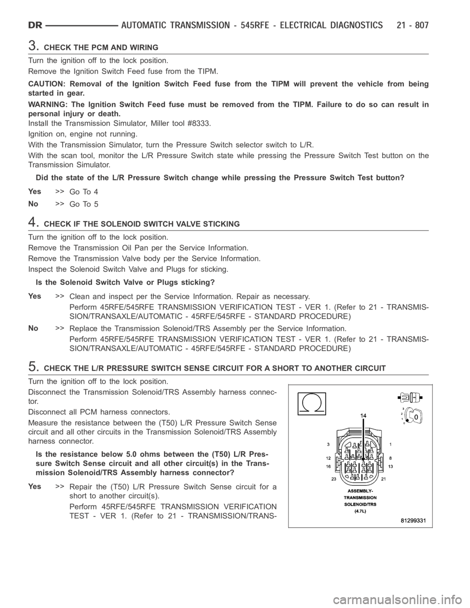
5.CHECK THE L/R PRESSURE SWITCH SENSE CIRCUIT FOR A SHORT TO ANOTHER CIRCUIT
Turn the ignition off to the lock position.
Disconnect the Transmission Solenoid/TRS Assembly harness connec-
tor.
Disconnect all PCM harness connectors.
Measure the resistance between the (T50) L/R Pressure Switch Sense
circuit and all other circuits in the Transmission Solenoid/TRS Assembly
harness connector.
Is the resistance below 5.0 ohms between the (T50) L/R Pres-
sure Switch Sense circuit and all other circuit(s) in the Trans-
mission Solenoid/TRS Assembly harness connector?
Ye s>>
Repair the (T50) L/R PressureSwitch Sense circuit for a
short to another circuit(s).
Perform 45RFE/545RFE TRANSMISSION VERIFICATION
TEST - VER 1. (Refer to 21 - TRANSMISSION/TRANS-
Page 3363 of 5267
page page
AUTOMATIC TRANSMISSION - 45RFE/545RFE -
SERVICE INFORMATION
DESCRIPTION ............................... 844
OPERATION ................................. 845
DIAGNOSIS AND TESTING
AUTOMATIC TRANSMISSION ............... 845
PRELIMINARY ............................. 846
ROAD TESTING ........................... 846
HYDRAULIC PRESSURE TEST............. 847
AIR CHECKING TRANSMISSION CLUTCH
OPERATION............................... 850
CONVERTER HOUSING FLUID LEAK ....... 850
STANDARD PROCEDURE - ALUMINUM
THREAD REPAIR .......................... 851
REMOVAL ................................... 851
DISASSEMBLY .............................. 854
CLEANING .................................. 860
INSPECTION ................................ 861
ASSEMBLY .................................. 861
INSTALLATION .............................. 871
SCHEMATICS AND DIAGRAMS
HYDRAULIC SCHEMATICS ................. 874
SPECIFICATIONS
TRANSMISSION ........................... 896
SPECIAL TOOLS
AUTOMATIC TRANSMISSION - RFE ......... 898
RETAINER/BULKHEAD-4C
DISASSEMBLY .............................. 901
ASSEMBLY .................................. 903
SEAL-ADAPTER HOUSING
REMOVAL ................................... 906
INSTALLATION .............................. 906
SYSTEM-BRAKE TRANSMISSION SHIFT
INTERLOCK
DESCRIPTION ............................... 907
OPERATION ................................. 907
DIAGNOSIS AND TESTING - BRAKE
TRANSMISSION SHIFT INTERLOCK ......... 907
ADJUSTMENTS - BRAKE TRANSMISSION
SHIFT INTERLOCK ......................... 907
FLUID AND FILTER
DIAGNOSIS AND TESTING
EFFECTS OF INCORRECT FLUID LEVEL.... 909
CAUSES OF BURNT FLUID ................. 909
FLUID CONTAMINATION ................... 909
STANDARD PROCEDURE
FLUID LEVEL CHECK . ..................... 909
FLUID AND FILTER REPLACEMENT ......... 911
TRANSMISSION FILL ...................... 912CABLE-GEARSHIFT
DIAGNOSIS AND TESTING - GEARSHIFT
CABLE .................................... 913
REMOVAL ................................... 913
INSTALLATION .............................. 914
ADJUSTMENTS - GEARSHIFT CABLE ......... 915
CLUTCHES-HOLDING
DESCRIPTION ............................... 916
OPERATION ................................. 917
ASSEMBLY-INPUT CLUTCH
DESCRIPTION ............................... 918
OPERATION ................................. 920
DISASSEMBLY .............................. 920
ASSEMBLY .................................. 925
SENSOR-INPUT SPEED
DESCRIPTION ............................... 932
OPERATION ................................. 932
REMOVAL ................................... 932
INSTALLATION .............................. 933
SENSOR-LINE PRESSURE
DESCRIPTION ............................... 934
OPERATION ................................. 934
REMOVAL ................................... 934
INSTALLATION .............................. 935
CLUTCH-LOW/REVERSE
DISASSEMBLY .............................. 936
CLEANING .................................. 937
INSPECTION . . .............................. 937
ASSEMBLY .................................. 938
PUMP-OIL
DESCRIPTION ............................... 940
OPERATION ................................. 942
STANDARD PROCEDURE - OIL PUMP
VOLUME CHECK .......................... 942
DISASSEMBLY .............................. 943
CLEANING .................................. 945
INSPECTION . . .............................. 946
ASSEMBLY .................................. 946
SEAL-OIL PUMP FRONT
REMOVAL ................................... 950
INSTALLATION .............................. 950
SENSOR-OUTPUT SPEED
DESCRIPTION ............................... 951
OPERATION ................................. 951
REMOVAL ................................... 951
INSTALLATION .............................. 952
SWITCH-TOW/HAUL OVERDRIVE
DESCRIPTION ............................... 953
OPERATION ................................. 953
REMOVAL ................................... 953
Page 3365 of 5267
AUTOMATIC TRANSMISSION - 45RFE/545RFE-SERVICEINFORMATION
DESCRIPTION
The 45RFE/545RFE automatic transmissions is a sophisticated, multi-range, electronically controlled transmission
which combines optimized gear ratios for responsive performance, state of the art efficiency features and low NVH.
Other features include driver adaptive shifting and three planetary gearsets to provide wide ratio capability with
precise ratio steps for optimum driveability. The three planetary gear sets also make available a unique alternate
second gear ratio. The primary 2nd gear ratio fits between 1st and 3rd gearsfor normal through-gear accelerations.
The alternate second gear ratio (2prime) allows smoother 4-2 kickdowns athigh speeds to provide 2nd gear pass-
ing performance over a wider highway cruising range.
The hydraulic portion of the transmission consists of the transmission fluid, fluid passages, hydraulic valves, and
various line pressure control components.
The primary mechanical components of the transmission consist of the following:
Three multiple disc input clutches
Three multiple disc holding clutches
Five hydraulic accumulators
Three planetary gear sets
Dual Stage Hydraulic oil pump
Valve body
Solenoid pack
The Transmission Control Module (TCM) is the “heart” or “brain” of the electronic control system and relies on infor-
mation from various direct and indirect inputs (sensors, switches, etc.)to determine driver demand and vehicle oper-
ating conditions. Depending on the vehicle configuration, the TCM may be astandalone module or it it may be
housed along with the Powertrain Control Module (PCM) in a single module. With this information, the TCM can
calculate and perform timely and quality shifts through various output orcontrol devices (solenoid pack, transmission
control relay, etc.).
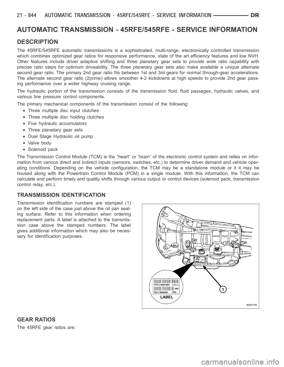
TRANSMISSION IDENTIFICATION
Transmission identification numbers are stamped (1)
on the left side of the case just above the oil pan seal-
ing surface. Refer to this information when ordering
replacement parts. A label is attached to the transmis-
sion case above the stamped numbers. The label
gives additional information which may also be neces-
sary for identification purposes.
GEAR RATIOS
The 45RFE gear ratios are:
Page 3367 of 5267
Improper adjustments
Hydraulic malfunctions
Mechanical malfunctions
Electronic malfunctions
Diagnosis of these problems should always begin by checking the easily accessible variables: fluid level and con-
dition, gearshift cable adjustment. Then perform a road test to determineif the problem has been corrected or if
more diagnosis is necessary. If the problem persists after the preliminary tests and corrections are completed,
hydraulic pressure checks should be performed.
PRELIMINARY
Two basic procedures are required. One procedure for vehicles that are drivable and an alternate procedure for
disabled vehicles (will not back up or move forward).
VEHICLE IS DRIVABLE
1. Check for transmission fault codes using scan tool.
2. Check fluid level and condition.
3. Adjust gearshift cable if complaint was based on delayed, erratic, or harsh shifts.
4. Road test and note how transmission upshifts, downshifts, and engages.
5. Perform hydraulic pressure test if shift problems were noted during roadtest.
6. Perform air-pressure test to check clutch operation.
VEHICLE IS DISABLED
1. Check fluid level and condition.
2. Check for broken or disconnected gearshift cable.
3. Check for cracked, leaking cooler lines, or loose or missing pressure-port plugs.
4. Raise and support vehicle on safety stands, start engine, shift transmission into gear, and note following:
a. If propeller shaft turns but wheels do not, problem is with differentialor axle shafts.
b. If propeller shaft does not turn and transmission is noisy, stop engine.Remove oil pan, and check for debris.
If pan is clear, remove transmission and check for damaged driveplate, converter, oil pump, or input shaft.
c. If propeller shaft does not turn and transmission is not noisy, perform hydraulic-pressure test to determine if
problem is hydraulic or mechanical.
ROAD TESTING
Before road testing, be sure the fluid level and control cable adjustmentshave been checked and adjusted if nec-
essary. Verify that all diagnostic trouble codes have been resolved.
Observe engine performance during the road test. A poorly tuned engine will not allow accurate analysis of trans-
mission operation.
Operate the transmission in all gear ranges. Check for shift variations and engine flare which indicates slippage.
Note if shifts are harsh, spongy, delayed, early, or if part throttle downshifts are sensitive.
Slippage indicated by engine flare, usually means clutch, overrunning clutch, or line pressure problems.
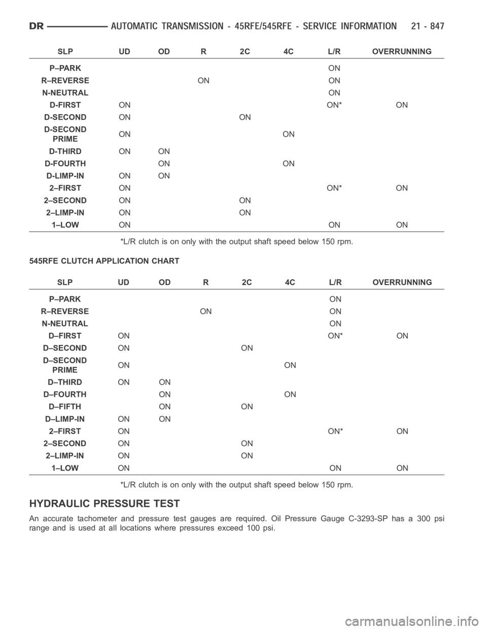
A slipping clutch can often be determined by comparing which internal units are applied in the various gear ranges.
The Clutch Application charts provide a basis for analyzing road test results.
45RFE CLUTCH APPLICATION CHART
Page 3368 of 5267
SLP UD OD R 2C 4C L/R OVERRUNNING
P–PARKON
R–REVERSEON ON
N-NEUTRALON
D-FIRSTON ON* ON
D-SECONDON ON
D-SECOND
PRIMEON ON
D-THIRDON ON
D-FOURTHON ON
D-LIMP-INON ON
2–FIRSTON ON* ON
2–SECONDON ON
2–LIMP-INON ON
1–LOWON ON ON
*L/R clutch is on only with the output shaft speed below 150 rpm.
545RFE CLUTCH APPLICATION CHART
SLP UD OD R 2C 4C L/R OVERRUNNING
P–PARKON
R–REVERSEON ON
N-NEUTRALON
D–FIRSTON ON* ON
D–SECONDON ON
D–SECOND
PRIMEON ON
D–THIRDON ON
D–FOURTHON ON
D–FIFTHON ON
D–LIMP-INON ON
2–FIRSTON ON* ON
2–SECONDON ON
2–LIMP-INON ON
1–LOWON ON ON
*L/R clutch is on only with the output shaft speed below 150 rpm.
HYDRAULIC PRESSURE TEST
An accurate tachometer and pressure test gauges are required. Oil Pressure Gauge C-3293-SP has a 300 psi
range and is used at all locations where pressures exceed 100 psi.