Page 3370 of 5267
line pressure reading should match the gauge reading within ±10 psi.
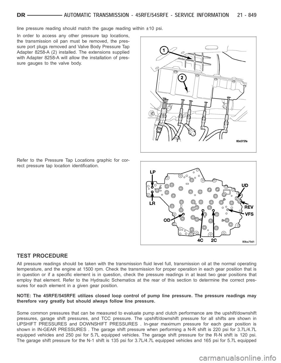
In order to access any other pressure tap locations,
the transmission oil pan must be removed, the pres-
sure port plugs removed and Valve Body Pressure Tap
Adapter 8258-A (2) installed. The extensions supplied
with Adapter 8258-A will allow the installation of pres-
sure gauges to the valve body.
Refer to the Pressure Tap Locations graphic for cor-
rect pressure tap location identification.
TEST PROCEDURE
All pressure readings should be taken with the transmission fluid level full, transmission oil at the normal operating
temperature, and the engine at 1500 rpm. Check the transmission for properoperation in each gear position that is
in question or if a specific element is in question, check the pressure readings in at least two gear positions that
employ that element. Refer to the Hydraulic Schematics at the rear of this section to determine the correct pres-
sures for each element in a given gear position.
NOTE: The 45RFE/545RFE utilizes closed loop control of pump line pressure. The pressure readings may
therefore vary greatly but should always follow line pressure.
Some common pressures that can be measured to evaluate pump and clutch performance are the upshift/downshift
pressures, garage shift pressures, and TCC pressure. The upshift/downshift pressure for all shifts are shown in
UPSHIFT PRESSURES and DOWNSHIFT PRESSURES . In-gear maximum pressure foreach gear position is
shown in IN-GEAR PRESSURES . The garageshift pressure when performing a N-R shift is 220 psi for 3.7L/4.7L
equipped vehicles and 250 psi for 5.7L equipped vehicles. The garage shiftpressure for the R-N shift is 120 psi.
The garage shift pressure for the N-1 shift is 135 psi for 3.7L/4.7L equipped vehicles and 165 psi for 5.7L equipped
Page 3371 of 5267
vehicles. Torque converter lock-up pressure is 120 psi for 3.7L/4.7L equipped vehicles and 125 psi for 5.7L
equipped vehicles.
UPSHIFT PRESSURES
ENGINE 1-2 2-3 2prime-3 3-4 2prime-4 2-5 3-5 4-5
5.7L150 125 125 135 135 135 135 135
3.7L/4.7L120 120 120 120 120 120 120 130
DOWNSHIFT PRESSURES
ENGINE 5-4 5-3 5-2 4-3 4-
2prime3-2 3-
2prime2prime-1 2-1 3-1
5.7L135 135 135 135 135 135 135 135 135 135
3.7L/
4.7L120 120 120 120 120 120 120 120 120 120
IN-GEAR PRESSURES
ENGINE122prime345NEUTRALREVERSE
5.7L160 135 135 135 135 135 120 250
3.7L/4.7L135 120 120 120 120 120 120 220
AIR CHECKING TRANSMISSION CLUTCH OPERATION
Air-pressure testing can be used to check transmis-
sion clutch operation. The test can be conducted with
the transmission either in the vehicle or on the work
bench, as a final check.
Air-pressure testing requires that the oil pan and valve
body be removed from the transmission. The clutch
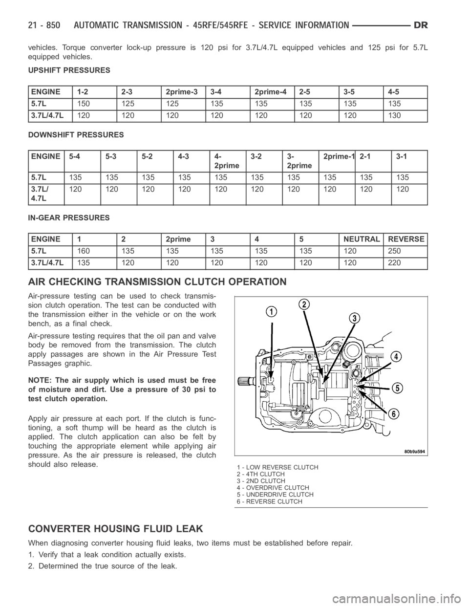
apply passages are shown in the Air Pressure Test
Passages graphic.
NOTE: The air supply which is used must be free
ofmoistureanddirt.Useapressureof30psito
test clutch operation.
Apply air pressure at each port. If the clutch is func-
tioning, a soft thump will be heard as the clutch is
applied. The clutch application can also be felt by
touching the appropriate element while applying air
pressure. As the air pressure is released, the clutch
should also release.
CONVERTER HOUSING FLUID LEAK
When diagnosing converter housing fluid leaks, two items must be established before repair.
1. Verify that a leak condition actually exists.
2. Determined the true source of the leak.
1 - LOW REVERSE CLUTCH
2 - 4TH CLUTCH
3 - 2ND CLUTCH
4-OVERDRIVECLUTCH
5 - UNDERDRIVE CLUTCH
6 - REVERSE CLUTCH
Page 3391 of 5267

49. Install the valve body. Verify that the pin on the
manual lever has properly engaged the TRS
selector plate. Tighten the valve body to transmis-
sion case bolts (1) to 12 Nꞏm (105 in.lbs.).
CAUTION: The primary oil filter seal MUST be fully
installed flush against the oil pump body. DO NOT
install the seal onto the filter neck and attempt to
install the filter and seal as an assembly. Damage
to the transmission will result.
50. Install a new primary oil filter seal in the oil pump
inlet bore. Seat the seal in the bore with the butt
end of a hammer, or other suitable tool.
51. Install the primary oil filter (1) and the oil cooler
return filter (2). Tighten the screw to hold the pri-
mary oil filter to the valve body to 4.5 Nꞏm (40
in.lbs.). Using Filter Wrench 8321, tighten the
cooler return oil filter to the transmission case to
9.5 Nꞏm (7 ft.lbs.).
52. Apply RTV silicone to theoil pan and install the
transmission oil pan. Tighten the bolts to 12 Nꞏm (105 in.lbs.).
53. Install the input (3), output (1), and line pressure
sensors (2). Tighten the bolts to 12 Nꞏm (105
in.lbs.).
Page 3417 of 5267
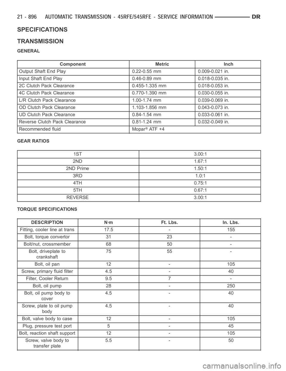
SPECIFICATIONS
TRANSMISSION
GENERAL
Component Metric Inch
Output Shaft End Play 0.22-0.55 mm 0.009-0.021 in.
Input Shaft End Play 0.46-0.89 mm 0.018-0.035 in.
2C Clutch Pack Clearance 0.455-1.335 mm 0.018-0.053 in.
4C Clutch Pack Clearance 0.770-1.390 mm 0.030-0.055 in.
L/R Clutch Pack Clearance 1.00-1.74 mm 0.039-0.069 in.
OD Clutch Pack Clearance 1.103-1.856 mm 0.043-0.073 in.
UD Clutch Pack Clearance 0.84-1.54 mm 0.033-0.061 in.
Reverse Clutch Pack Clearance 0.81-1.24 mm 0.032-0.049 in.
Recommended fluid Mopar
AT F + 4
GEAR RATIOS
1ST 3.00:1
2ND 1.67:1
2ND Prime 1.50:1
3RD 1.0:1
4TH 0.75:1
5TH 0.67:1
REVERSE 3.00:1
TORQUE SPECIFICATIONS
DESCRIPTION Nꞏm Ft. Lbs. In. Lbs.
Fitting, cooler line at trans 17.5 - 155
Bolt, torque convertor 31 23 -
Bolt/nut, crossmember 68 50 -
Bolt, driveplate to
crankshaft75 55 -
Bolt, oil pan 12 - 105
Screw, primary fluid filter 4.5 - 40
Filter, Cooler Return 9.5 7 -
Bolt, oil pump 28 - 250
Bolt, oil pump body to
cover4.5 - 40
Screw, plate to oil pump
body4.5 - 40
Bolt, valve body to case 12 - 105
Plug, pressure test port 5 - 45
Bolt, reaction shaft support 12 - 105
Screw, valve body to
transfer plate5.5 - 50
Page 3419 of 5267
SPECIAL TOOLS
AUTOMATIC TRANSMISSION - RFE
Gauge, Oil Pressure - C-3292
Gauge, Oil Pressure - C-3293SP
Dial Indicator - C-3339
Installer, Seal - C-3860-A
Compressor, Spring - 8249
Compressor, Spring - 8250
Compressor, Spring - 8251
Installer, Piston - 8252
Installer, Seal - 8253
Page 3430 of 5267
FLUID AND FILTER
DIAGNOSIS AND TESTING
EFFECTS OF INCORRECT FLUID LEVEL
Alowfluidlevelallowsthepumptotakeinairalongwiththefluid.Airinthe fluid will cause fluid pressures to be
low and develop slower than normal. If the transmission is overfilled, thegears churn the fluid into foam. This aer-
ates the fluid and causing the same conditions occurring with a low level. In either case, air bubbles cause fluid
overheating, oxidation, and varnish buildup which interferes with valveand clutch operation. Foaming also causes
fluid expansion which can result in fluid overflow from the transmission vent or fill tube. Fluid overflow can easily be
mistaken for a leak if inspection is not careful.
CAUSES OF BURNT FLUID
Burnt, discolored fluid is a result of overheating which has three primarycauses.
1. Internal clutch slippage, usually caused by low line pressure, inadequate clutch apply pressure, or clutch seal
failure.
2. A result of restricted fluid flow through the main and/or auxiliary cooler. This condition is usually the result of a
faulty or improperly installed drainback valve, a damaged oil cooler, or severe restrictions in the coolers and lines
caused by debris or kinked lines.
3. Heavy duty operation with a vehicle not properly equipped for this type of operation. Trailer towing or similar high
load operation will overheat the transmission fluid if the vehicle is improperly equipped. Such vehicles should
have an auxiliary transmission fluid cooler, a heavy duty cooling system,and the engine/axle ratio combination
needed to handle heavy loads.
FLUID CONTAMINATION
Transmission fluid contamination is generally a result of:
adding incorrect fluid
failure to clean dipstick and fill tube when checking level
engine coolant entering the fluid
internal failure that generates debris
overheat that generates sludge (fluid breakdown)
failure to replace contaminated converter after repair
The use of non-recommended fluids can result in transmission failure. Theusual results are erratic shifts, slippage,
abnormal wear and eventual failure due to fluid breakdown and sludge formation. Avoid this condition by using rec-
ommended fluids only.
The dipstick cap and fill tube should be wiped clean before checking fluid level. Dirt, grease and other foreign mate-
rial on the cap and tube could fall into the tube if not removed beforehand. Take the time to wipe the cap and tube
clean before withdrawing the dipstick.
Engine coolant in the transmission fluid is generally caused by a cooler malfunction. The only remedy is to replace
the radiator as the cooler in the radiator is not a serviceable part. If coolant has circulated through the transmission,
an overhaul is necessary.
The torque converter should also be replaced whenever a failure generatessludge and debris. This is necessary
because normal converter flushing procedures will not remove all contaminants.
STANDARD PROCEDURE
FLUID LEVEL CHECK
Low fluid level can cause a variety of conditions because it allows the pumpto take in air along with the fluid. As
in any hydraulic system, air bubbles make the fluid spongy, therefore, pressures will be low and build up slowly.
Improper filling can also raise the fluid level too high. When the transmssion has too much fluid, the geartrain
churns up foam and cause the same conditions which occur with a low fluid level.
Page 3455 of 5267
SENSOR-LINE PRESSURE
DESCRIPTION
The TCM utilizes a closed-loop system to control transmission line pressure. The system contains a variable force
style solenoid, the Pressure Control Solenoid, mounted on the side of the solenoid and pressure switch assembly.
The solenoid is duty cycle controlled by the TCM to vent the unnecessary line pressure supplied by the oil pump
back to the sump. The system also contains a variable pressure style sensor, the Line Pressure Sensor, which is a
direct input to the TCM. The line pressure solenoid monitors the transmission line pressure and completes the feed-
back loop to the TCM. The TCM uses this information to adjust its control of the pressure control solenoid to
achieve the desired line pressure.
OPERATION
The TCM calculates the desired line pressure based upon inputs from the transmission and engine. The TCM cal-
culates the torque input to the transmission and uses that information as the primary input to the calculation. The
line pressure is set to a predetermined value during shifts and when the transmission is in the PARK and NEUTRAL
positions. This is done to ensure consistent shift quality. During all other operation, the actual line pressure is com-
pared to the desired line pressure and adjustments are made to the pressurecontrol solenoid duty cycle.
REMOVAL
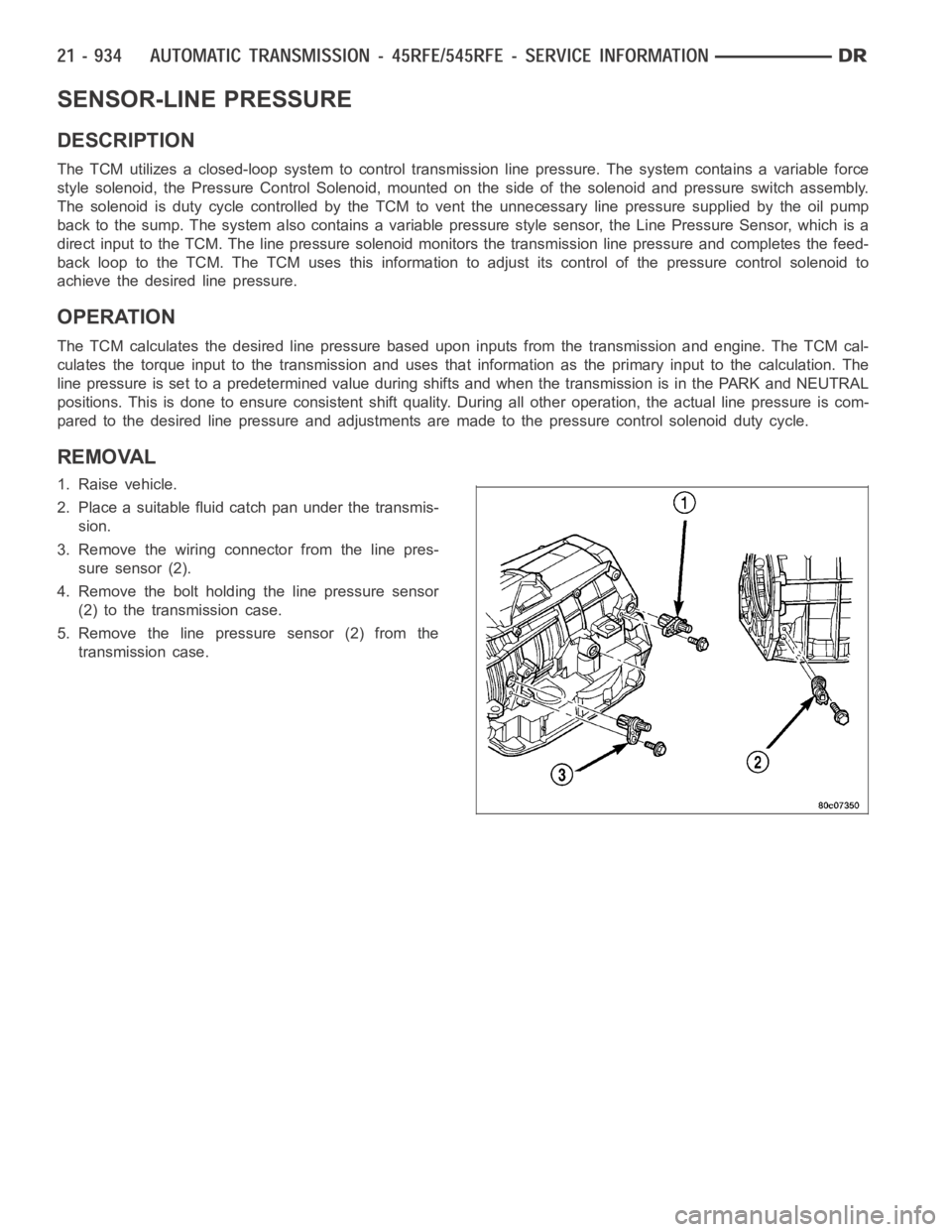
1. Raise vehicle.
2. Place a suitable fluid catch pan under the transmis-
sion.
3. Remove the wiring connector from the line pres-
sure sensor (2).
4. Remove the bolt holding the line pressure sensor
(2) to the transmission case.
5. Remove the line pressure sensor (2) from the
transmission case.
Page 3462 of 5267
The oil pump also contains a number of valves. The
converter clutch switch (3) and control valves (2),
pressure regulator valve (5), and converter pressure
limit valve (6) are all located in the oil pump valve
body.
A front seal (2), and a bolt on reaction shaft (5) complete the oil pump assembly.
Oil Pump Reaction Shaft
1 - PUMP HOUSING 4 - SEAL RING (5)
2 - SEAL 5 - REACTION SHAFT SUPPORT
3 - OIL FILTER SEAL 6 - PUMP VALVE BODY