2006 DODGE RAM SRT-10 oil pressure
[x] Cancel search: oil pressurePage 3463 of 5267
OPERATION
As the torque converter rotates, the converter hub rotates the oil pump drive gear. As the drive gear rotates both
driven gears, a vacuum is created when the gear teeth come out of mesh. This suction draws fluid through the
pump inlet from the oil pan. As the gear teeth come back into mesh, pressurized fluid is forced into the pump outlet
and to the oil pump valves.
At low speeds, both sides of the pump supply fluid to the transmission. As the speed of the torque converter
increases, the flow from both sides increases until the flow from the primary side alone is sufficient to meet system
demands. At this point, the check valve located between the two pumps closes. The secondary side is shut down
and the primary side supplies all the fluid to the transmission.
CONVERTER CLUTCH SWITCH VALVE
The converter clutch switch valve is used to control the hydraulic pressure supplied to the front (OFF) side of the
torque converter clutch.
CONVERTER CLUTCH REGULATOR VALVE
The converter clutch regulator valve is used to control the hydraulic pressure supplied to the back (ON) side of the
torque converter clutch.
TORQUE CONVERTER LIMIT VALVE
The torque converter limit valve serves to limit the available line pressure to the torque converter clutch.
STANDARD PROCEDURE - OIL PUMP VOLUME CHECK
Measuring the oil pump output volume will determine if sufficient oil flowto the transmission oil cooler exists, and
whether or not an internal transmission failure is present.
Verify that the transmission fluid is at the proper level. Refer to the Fluid Level Check procedure in this section. If
necessary, fill the transmission to the proper level with Mopar
ATF +4, Automatic Transmission Fluid.
1. Disconnect theTo coolerline at the cooler inlet and place a collecting container under the disconnected line.
CAUTION: With the fluid set at the proper level, fluid collection should not exceed (1) quart or internal dam-
age to the transmission may occur.
2. Run the engineat 1800 rpm, with the shift selector in neutral. Verify that the transmission fluid temperature is
below 104.5° C (220° F) for this test.
3. If one quart of transmission fluid is collected in the container in 30 seconds or less, oil pump flow volume is
within acceptable limits. If fluid flow is intermittent, or it takes more than 30 seconds to collect one quart of fluid,
refer to the Hydraulic Pressure tests in this section for further diagnosis.
4. Re-connect theTo c o o l e rline to the transmission cooler inlet.
5. Refill the transmission to proper level.
Page 3486 of 5267
TURBINE
As the fluid that was put into motion bythe impeller blades strikes the blades of the turbine, some of the energy and
rotational force is transferred into the turbine and the input shaft. Thiscauses both of them (turbine and input shaft)
to rotate in a clockwise direction following the impeller. As the fluid is leaving the trailing edges of the turbine’s
blades it continues in a “hindering” direction back toward the impeller. If the fluid is not redirected before it strikes
the impeller, it will strike the impeller in such a direction that it would tend to slow it down.
STATOR
Torque multiplication is achieved by locking the stator’s over-running clutch to its shaft. Under stall conditions (the
turbine is stationary), the oil leaving the turbine blades strikes the face of the stator blades and tries to rotate them
in a counterclockwise direction. When this happens the over-running clutch of the stator locks and holds the stator
from rotating. With the stator locked, the oil strikes the stator blades and is redirected into a “helping” direction
before it enters the impeller. This circulation of oil from impeller to turbine, turbine to stator, and stator to impeller,
can produce a maximum torque multiplicationofabout2.4:1.Astheturbinebegins to match the speed of the impel-
ler, the fluid that was hitting the stator in such as way as to cause it to lock-up is no longer doing so. In this con-
dition of operation, the stator begins to free wheel and the converter actsas a fluid coupling.
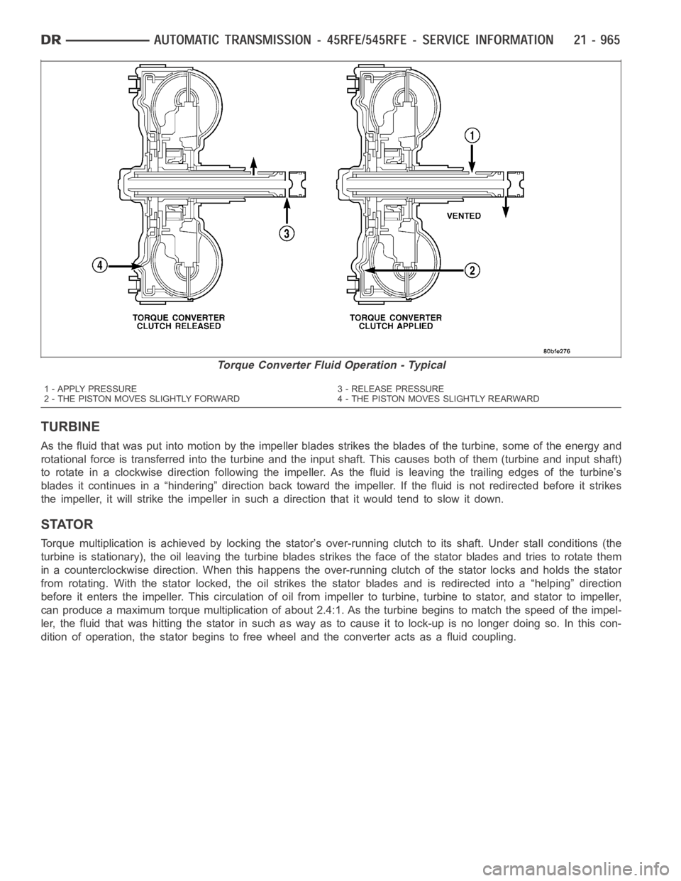
Torque Converter Fluid Operation - Typical
1 - APPLY PRESSURE 3 - RELEASE PRESSURE
2 - THE PISTON MOVES SLIGHTLY FORWARD 4 - THE PISTON MOVES SLIGHTLY REARWARD
Page 3497 of 5267
LOW/REVERSE SWITCH VALVE
The low/reverse switch valve allows the low/reverse clutch to be operatedby either the LR/CC solenoid or the MS
solenoid.
REMOVAL
NOTE: The valve body can be removed for service without having to remove thetransmission assembly.
The valve body can be disassembled for cleaning and inspection of the individual components. (Refer to 21
- TRANSMISSION/AUTOMATIC - 45RFE/VALVE BODY - DISASSEMBLY)
1. Shift transmission into PARK.
2. Raise vehicle.
3. Disconnect wires at the solenoid and pressure
switch assembly connector.
4. Position drain pan under transmission oil pan.
5. Remove transmission oil pan.
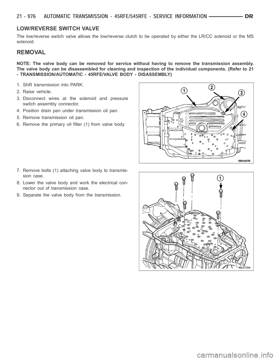
6. Remove the primary oil filter (1) from valve body.
7. Remove bolts (1) attaching valve body to transmis-
sion case.
8. Lower the valve body and work the electrical con-
nector out of transmission case.
9. Separate the valve body from the transmission.
Page 3502 of 5267
INSPECTION
Inspect all of the valve body mating surfaces for scratches, nicks, burrs,or distortion. Use a straightedge to check
surface flatness. Minor scratches may be removed with crocus cloth using only very light pressure.
Minor distortion of a valve body mating surface may be corrected by smoothing the surface with a sheet of crocus
cloth. Position the crocus cloth on a surface plate, sheet of plate glass orequally flat surface. If distortion is severe
or any surfaces are heavily scored, the valve body will have to be replaced.
Inspect the valves and plugs for scratches, burrs, nicks, or scores. Minorsurface scratches on steel valves and
plugs can be removed with crocus cloth butdo not round off the edges of the valve or plug lands.Maintaining
sharpness of these edges is vitally important. The edges prevent foreign matter from lodging between the valves
and plugs and the bore.
Inspect all the valve and plug bores in the valve body. Use a penlight to viewthe bore interiors. Replace the valve
body if any bores are distorted or scored. Inspect all of the valve body springs. The springs must be free of dis-
tortion, warpage or broken coils.
Trial fit each valve and plug in its bore to check freedom of operation. Whenclean and dry, the valves and plugs
shoulddropfreelyintothebores.
Valve body bores do not change dimensionally with use. If the valve body functioned correctly when new, it will
continue to operate properly after cleaning and inspection. It should notbe necessary to replace a valve body
assembly unless it is damaged in handling.
Inspect all the accumulator bores in the valve body. Use a penlight to view the bore interiors. Replace the valve
body if any bores are distorted or scored. Inspect all of the accumulator springs. The springs must be free of dis-
tortion, warpage or broken coils.
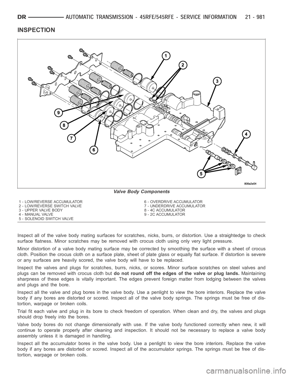
Valve Body Components
1 - LOW/REVERSE ACCUMULATOR 6 - OVERDRIVE ACCUMULATOR
2 - LOW/REVERSE SWITCH VALVE 7 - UNDERDRIVE ACCUMULATOR
3 - UPPER VALVE BODY 8 - 4C ACCUMULATOR
4 - MANUAL VALVE 9 - 2C ACCUMULATOR
5 - SOLENOID SWITCH VALVE
Page 3507 of 5267
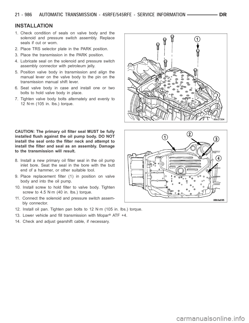
INSTALLATION
1. Check condition of seals on valve body and the
solenoid and pressure switch assembly. Replace
seals if cut or worn.
2. Place TRS selector plate in the PARK position.
3. Place the transmission in the PARK position.
4. Lubricate seal on the solenoid and pressure switch
assembly connector with petroleum jelly.
5. Position valve body in transmission and align the
manual lever on the valve body to the pin on the
transmission manual shift lever.
6. Seat valve body in case and install one or two
bolts to hold valve body in place.
7. Tighten valve body bolts alternately and evenly to
12 Nꞏm (105 in. lbs.) torque.
CAUTION: The primary oil filter seal MUST be fully
installed flush against the oil pump body. DO NOT
install the seal onto the filter neck and attempt to
install the filter and seal as an assembly. Damage
to the transmission will result.
8. Install a new primary oil filter seal in the oil pump
inlet bore. Seat the seal in the bore with the butt
end of a hammer, or other suitable tool.
9. Place replacement filter (1) in position on valve
body and into the oil pump.
10. Install screw to hold filter to valve body. Tighten
screw to 4.5 Nꞏm (40 in. lbs.) torque.
11. Connect the solenoid and pressure switch assem-
bly connector.
12. Install oil pan. Tighten pan bolts to 12 Nꞏm (105 in. lbs.) torque.
13. Lower vehicle and fill transmission with Mopar
AT F + 4 .
14. Check and adjust gearshift cable, if necessary.
Page 3513 of 5267
Turn the ignition off to the lock position.
Remove the Transmission Oil Pan per the Service Information. (Refer to 21 -TRANSMISSION/TRANSAXLE/AU-
TOMATIC - 48RE/FLUID - STANDARD PROCEDURE)
Disconnect the Governor Pressure Sensor harness connector internal to the transmission.
NOTE: Check connectors - Clean/repair as necessary
Measure the resistance of the Transmission Temperature Sensor between the (T54) Transmission Temperature Sen-
sor Signal circuit and the (K900) Sensor Ground circuit.
Using the chart at the chart above, compare the Temperature Sensor temperature to the correlating resistance
value.
Is the resistance within the specified range when the sensor is at the giventemperature?
Ye s>>
Te s t C o m p l e t e .
No>>
Replace the Governor Pressure/Transmission Temperature Sensor per the Service Information. (Refer to
21 - TRANSMISSION/TRANSAXLE/AUTOMATIC - 48RE/GOVERNOR PRESSURE SENSOR-
REMOVAL)
Perform RE TRANSMISSION VERIFICATION TEST VER - 1 (GAS). (Refer to 21 - TRANSMISSION/
TRANSAXLE/AUTOMATIC - 48RE - STANDARD PROCEDURE)
6.INTERMITTENT WIRING AND CONNECTORS
The conditions necessary to set this DTC are not present at this time.
Use the Freeze Frame Data to help duplicate the conditions in which the DTC originally set. Pay particular attention
to the DTC set conditions, such as, VSS, MAP, ECT, and Load.
Using the schematics as a guide, visually inspect the related wiring harness. Look for any chafed, pierced, pinched,
or partially broken wires.
Visually inspect the related wiring harness connectors. Look for broken,bent, pushed out, or corroded terminals.
Wiggle the wiring and connectors while checking for any possible open or shorted circuits.
Check for any Service Information Tune-ups or Technical Service Bulletins that may apply.
Were there any problems found?
Ye s>>
Repair as necessary.
Perform RE TRANSMISSION VERIFICATION TEST VER - 1 (GAS). (Refer to 21 - TRANSMISSION/
TRANSAXLE/AUTOMATIC - 48RE - STANDARD PROCEDURE)
No>>
Te s t C o m p l e t e .
Page 3517 of 5267
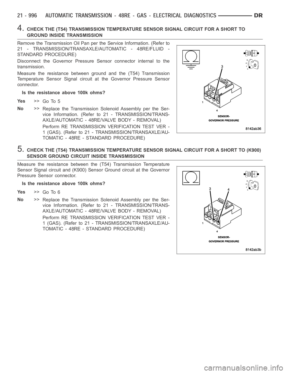
4.CHECK THE (T54) TRANSMISSION TEMPERATURE SENSOR SIGNAL CIRCUIT FOR A SHORTTO
GROUND INSIDE TRANSMISSION
Remove the Transmission Oil Pan perthe Service Information. (Refer to
21 - TRANSMISSION/TRANSAXLE/AUTOMATIC - 48RE/FLUID -
STANDARD PROCEDURE)
Disconnect the Governor Pressure Sensor connector internal to the
transmission.
Measure the resistance between ground and the (T54) Transmission
Temperature Sensor Signal circuit at the Governor Pressure Sensor
connector.
Is the resistance above 100k ohms?
Ye s>>
Go To 5
No>>
Replace the Transmission Solenoid Assembly per the Ser-
vice Information. (Refer to 21 - TRANSMISSION/TRANS-
AXLE/AUTOMATIC - 48RE/VALVE BODY - REMOVAL)
Perform RE TRANSMISSION VERIFICATION TEST VER -
1 (GAS). (Refer to 21 - TRANSMISSION/TRANSAXLE/AU-
TOMATIC - 48RE - STANDARD PROCEDURE)
5.CHECK THE (T54) TRANSMISSION TEMPERATURE SENSOR SIGNAL CIRCUIT FOR A SHORT TO (K900)
SENSOR GROUND CIRCUIT INSIDE TRANSMISSION
Measure the resistance between the (T54) Transmission Temperature
Sensor Signal circuit and (K900) Sensor Ground circuit at the Governor
Pressure Sensor connector.
Is the resistance above 100k ohms?
Ye s>>
Go To 6
No>>
Replace the Transmission Solenoid Assembly per the Ser-
vice Information. (Refer to 21 - TRANSMISSION/TRANS-
AXLE/AUTOMATIC - 48RE/VALVE BODY - REMOVAL)
Perform RE TRANSMISSION VERIFICATION TEST VER -
1 (GAS). (Refer to 21 - TRANSMISSION/TRANSAXLE/AU-
TOMATIC - 48RE - STANDARD PROCEDURE)
Page 3524 of 5267
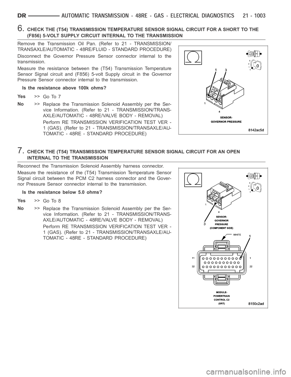
6.CHECK THE (T54) TRANSMISSION TEMPERATURE SENSOR SIGNAL CIRCUIT FOR A SHORTTOTHE
(F856) 5-VOLT SUPPLY CIRCUIT INTERNAL TO THE TRANSMISSION
Remove the Transmission Oil Pan. (Refer to 21 - TRANSMISSION/
TRANSAXLE/AUTOMATIC - 48RE/FLUID - STANDARD PROCEDURE)
Disconnect the Governor Pressure Sensor connector internal to the
transmission.
Measure the resistance between the (T54) Transmission Temperature
Sensor Signal circuit and (F856) 5-volt Supply circuit in the Governor
Pressure Sensor connector internal to the transmission.
Is the resistance above 100k ohms?
Ye s>>
Go To 7
No>>
Replace the Transmission Solenoid Assembly per the Ser-
vice Information. (Refer to 21 - TRANSMISSION/TRANS-
AXLE/AUTOMATIC - 48RE/VALVE BODY - REMOVAL)
Perform RE TRANSMISSION VERIFICATION TEST VER -
1 (GAS). (Refer to 21 - TRANSMISSION/TRANSAXLE/AU-
TOMATIC - 48RE - STANDARD PROCEDURE)
7.CHECK THE (T54) TRANSMISSION TEMPERATURE SENSOR SIGNAL CIRCUIT FOR AN OPEN
INTERNAL TO THE TRANSMISSION
Reconnect the Transmission Solenoid Assembly harness connector.
Measure the resistance of the (T54) Transmission Temperature Sensor
Signal circuit between the PCM C2 harness connector and the Gover-
nor Pressure Sensor connector internal to the transmission.
Is the resistance below 5.0 ohms?
Ye s>>
Go To 8
No>>
Replace the Transmission Solenoid Assembly per the Ser-
vice Information. (Refer to 21 - TRANSMISSION/TRANS-
AXLE/AUTOMATIC - 48RE/VALVE BODY - REMOVAL)
Perform RE TRANSMISSION VERIFICATION TEST VER -
1 (GAS). (Refer to 21 - TRANSMISSION/TRANSAXLE/AU-
TOMATIC - 48RE - STANDARD PROCEDURE)