2006 DODGE RAM SRT-10 transmission fluid
[x] Cancel search: transmission fluidPage 2592 of 5267
MANUAL TRANSMISSION - GETRAG 238 - SERVICE INFORMATION
DIAGNOSIS AND TESTING
MANUAL TRANSMISSION - GETRAG 238
LOW LUBRICANT LEVEL
A low transmission lubricant level is generally the result of a leak, inadequate lubricant fill or incorrect lubricant level
check.
Rear transmission leakswill be from the oil seals or transfer case front seal on 4x4.
Front transmission leakswill be from the front input shaft retainer seal. Lubricant may drip from theclutchhousing
after extended operation. If leak is severe, it may contaminate the clutchdisc.
Lubricant level checkcan only be made when the vehicle is level and allowing the lubricant to settle for a minute
before checking. This will ensure an accurate check and avoid an under or overfill condition.
HARD SHIFTING
Hard shifting can be caused by low lubricant level, improper or contaminated lubricants. This will cause noise,
excessive wear, internal bind, and hard shifting. Substantial lubricantleaks can result in gear, shift rail, synchro, and
bearing damage. The first indications of component damage is usually hardshifting and noise.
Shift component damage, clutch adjustment, worn pressure plate or disc, can increased shift effort. If clutch problem
is advanced, gear clash during shifts can result. Worn or damaged synchronizer rings can cause gear clash when
shifting into any forward gear. In some new or rebuilt transmissions, new synchro rings may tend to stick slightly
causing hard or noisy shifts. In most cases, this condition will decline asthe rings wear-in.
TRANSMISSION NOISE
Most manual transmissions make some noise during normal operation. Rotating gears generate a mild whine that is
audible, but generally only at extreme speeds.
Severe, highly audible transmission noise is generally the initial indicator of a lubricant problem. Insufficient,
improper or contaminated lubricant will promote rapid wear of gears, synchronizer rings, shift rails, forks and bear-
ings. The overheating caused by a lubricant problem, can also lead to gear and bearing damage.
STANDARD PROCEDURE
DRAIN AND FILL
1. Raise and support vehicle.
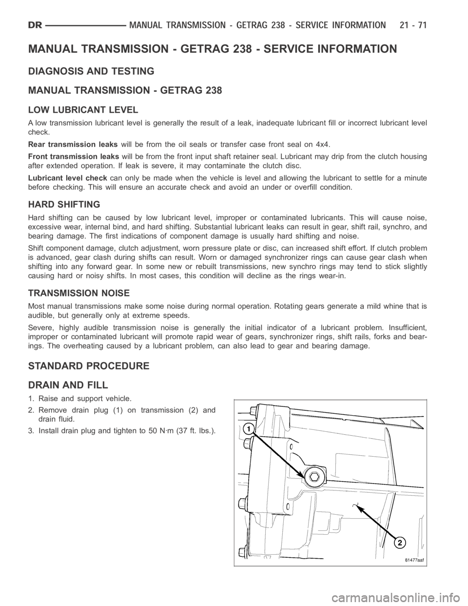
2. Remove drain plug (1) on transmission (2) and
drain fluid.
3. Install drain plug and tighten to 50 Nꞏm (37 ft. lbs.).
Page 2593 of 5267
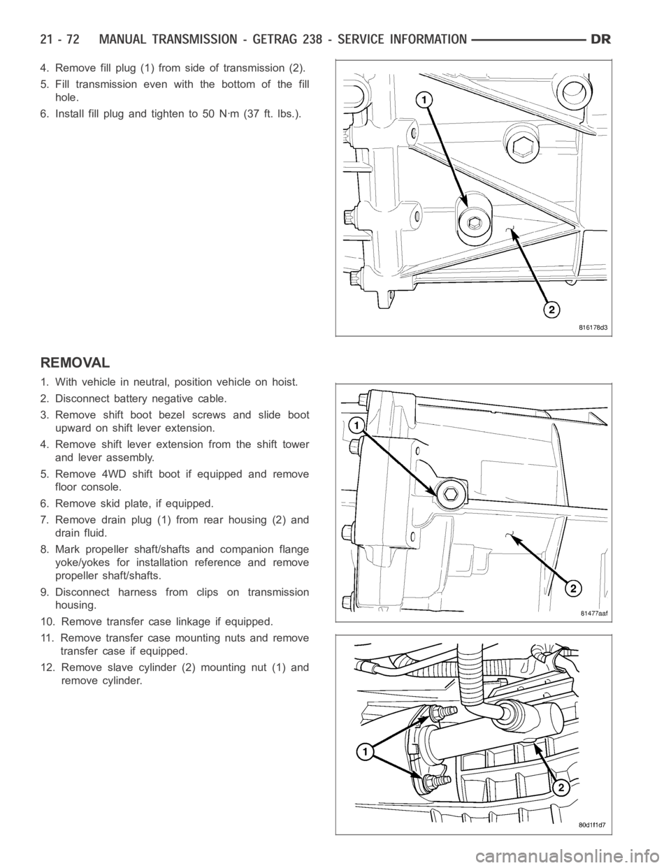
4. Remove fill plug (1) from side of transmission (2).
5. Fill transmission even with the bottom of the fill
hole.
6. Install fill plug and tighten to 50 Nꞏm (37 ft. lbs.).
REMOVAL
1. With vehicle in neutral, position vehicle on hoist.
2. Disconnect battery negative cable.
3. Remove shift boot bezel screws and slide boot
upward on shift lever extension.
4. Remove shift lever extension from the shift tower
and lever assembly.
5. Remove 4WD shift boot if equipped and remove
floor console.
6. Remove skid plate, if equipped.
7. Remove drain plug (1) from rear housing (2) and
drain fluid.
8. Mark propeller shaft/shafts and companion flange
yoke/yokes for installation reference and remove
propeller shaft/shafts.
9. Disconnect harness from clips on transmission
housing.
10. Remove transfer case linkage if equipped.
11. Remove transfer case mounting nuts and remove
transfer case if equipped.
12. Remove slave cylinder (2) mounting nut (1) and
remove cylinder.
Page 2664 of 5267
MANUAL TRANSMISSION-T56 - SERVICE INFORMATION
DIAGNOSIS AND TESTING
MANUAL TRANSMISSION - T56
LOW LUBRICANT LEVEL
A low transmission lubricant level is generally the result of a leak, inadequate lubricant fill or incorrect lubricant level
check.
Rear transmission leakswill be from the oil seals or component mating surfaces.
Front transmission leakswill be from the front bearing retainer or retainer seal. Lubricant may dripfromtheclutch
housing after extended operation. If leak is severe, it may contaminate the clutch disc.
Lubricant level checkcan only be made when the vehicle is level and allowing the lubricant to settle for a minute
before checking. This will ensure an accurate check and avoid an underfillor overfill condition.
HARD SHIFTING
Hard shifting is usually caused by low lubricant level, improper or contaminated lubricants. This will cause noise,
excessive wear, internal bind, and hard shifting. Substantial lubricantleaks can result in gear, shift rail, synchro, and
bearing damage. The first indications of component damage is usually hardshifting and noise.
Shift component damage, clutch adjustment, worn pressure plate or disc are also causes of increased shift effort. If
clutch problem is advanced, gear clash during shifts can result. Worn or damaged synchro rings can cause gear
clash when shifting into any forward gear. In some new or rebuilt transmissions, new synchro rings may tend to stick
slightly causing hard or noisy shifts. In most cases, this condition will decline as the rings wear-in.
TRANSMISSION NOISE
Most manual transmissions make some noise during normal operation. Rotating gears generate a mild whine that is
audible, but generally only at extreme speeds.
Severe, highly audible transmission noise is generally the initial indicator of a lubricant problem. Insufficient,
improper or contaminated lubricant will promote rapid wear of gears, synchros, shift rails, forks and bearings. The
overheating caused by a lubricant problem, can also lead to gear and bearing damage.
STANDARD PROCEDURE - DRAIN AND FILL
1. Raise and support vehicle.
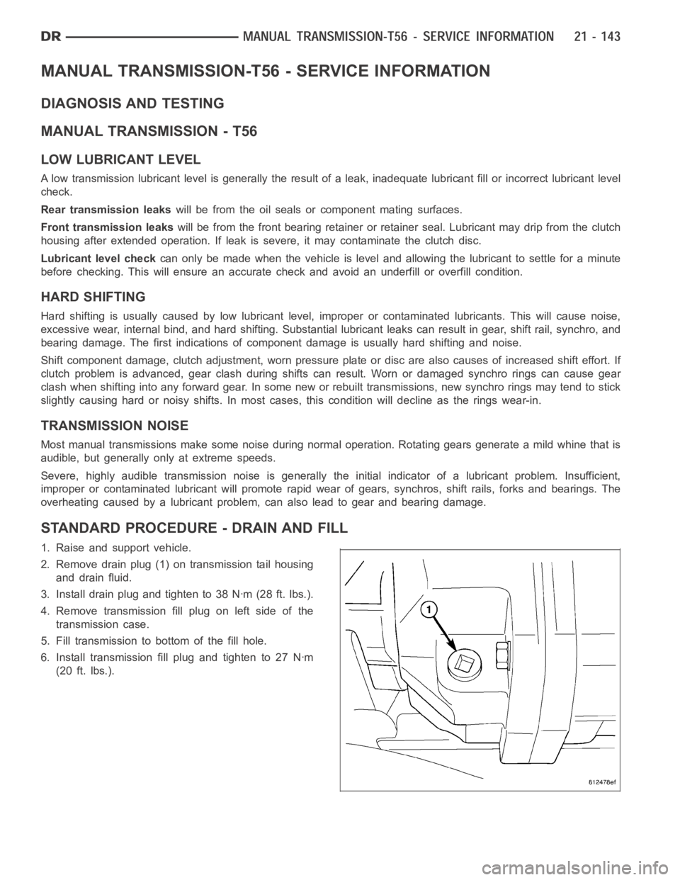
2. Remove drain plug (1) on transmission tail housing
and drain fluid.
3. Install drain plug and tighten to 38 Nꞏm (28 ft. lbs.).
4. Remove transmission fill plug on left side of the
transmission case.
5. Fill transmission to bottom of the fill hole.
6. Install transmission fill plug and tighten to 27 Nꞏm
(20 ft. lbs.).
Page 2719 of 5267
SEAL-EXTENSION HOUSING
REMOVAL
NOTE: If extension housing slip yoke bushing is
worn the housing must be replaced,
1. Remove propeller shaft.
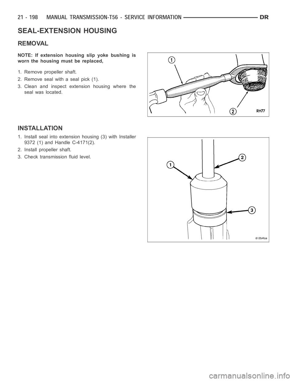
2. Remove seal with a seal pick (1).
3. Clean and inspect extension housing where the
seal was located.
INSTALLATION
1. Install seal into extension housing (3) with Installer
9372 (1) and Handle C-4171(2).
2. Install propeller shaft.
3. Check transmission fluid level.
Page 2721 of 5267
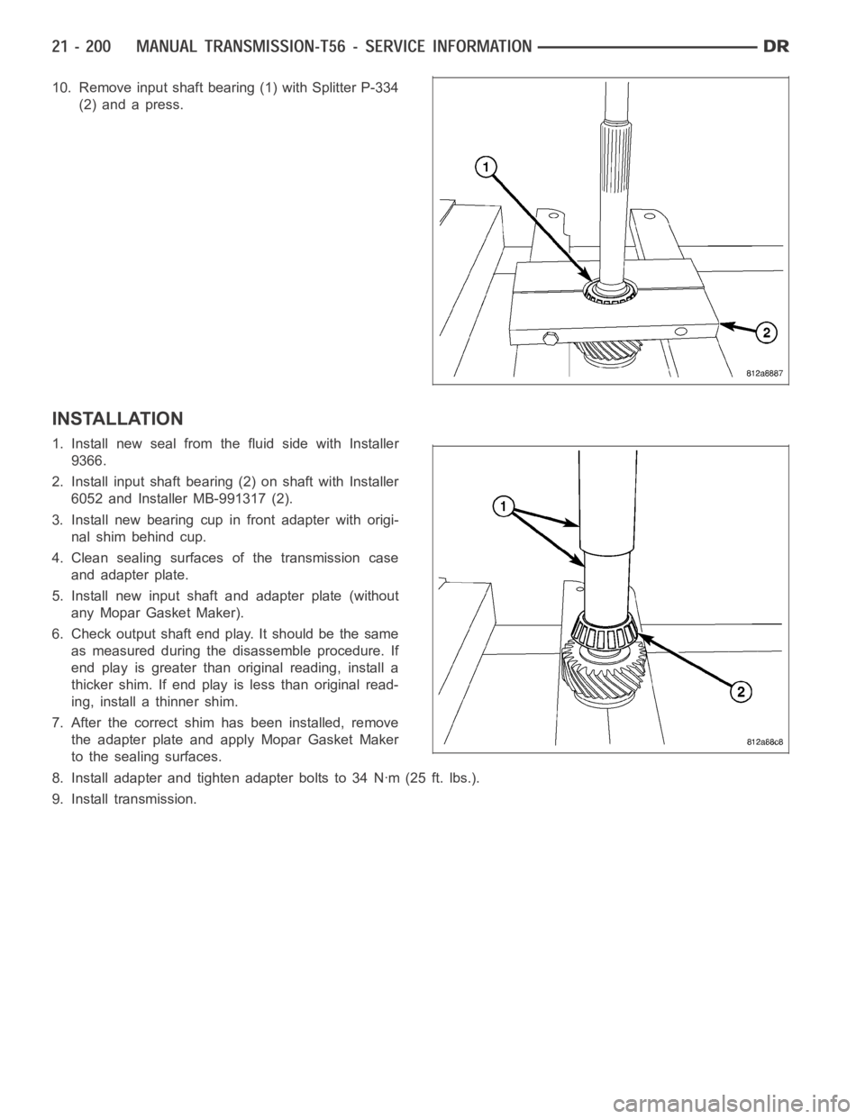
10. Remove input shaft bearing (1) with Splitter P-334
(2) and a press.
INSTALLATION
1. Install new seal from the fluid side with Installer
9366.
2. Install input shaft bearing (2) on shaft with Installer
6052 and Installer MB-991317 (2).
3. Install new bearing cup in front adapter with origi-
nal shim behind cup.
4. Clean sealing surfaces of the transmission case
and adapter plate.
5. Install new input shaft and adapter plate (without
any Mopar Gasket Maker).
6. Check output shaft end play. It should be the same
as measured during the disassemble procedure. If
end play is greater than original reading, install a
thicker shim. If end play is less than original read-
ing, install a thinner shim.
7. After the correct shim has been installed, remove
the adapter plate and apply Mopar Gasket Maker
to the sealing surfaces.
8. Install adapter and tighten adapter bolts to 34 Nꞏm (25 ft. lbs.).
9. Install transmission.
Page 2724 of 5267
page page
AUTOMATIC TRANSMISSION 42RLE -
ELECTRICAL DIAGNOSTICS
DIAGNOSIS AND TESTING
P0122-TPS/APP CIRCUIT LOW............. 205
P0123-TPS/APP CIRCUIT HIGH............. 207
P0124-TPS/APP INTERMITTENT ............ 209
P0218-HIGH TEMPERATURE OPERATION
A C T I VAT E D................................ 211
P0562-BATTERY VOLTAGE LOW ............ 213
P0602-CONTROL MODULE PROGRAMMING
ERROR/NOT PROGRAMMED............... 217
P0604-INTERNAL CONTROL MODULE RAM . 218
P0605-INTERNAL CONTROL MODULE ROM . 219
P0613-INTERNAL TRANSMISSION
PROCESSOR.............................. 220
P0706-TRANSMISSION RANGE SENSOR
RATIONALITY............................. 221
P0711-TRANSMISSION TEMPERATURE
SENSOR PERFORMANCE.................. 225
P0712-TRANSMISSION TEMPERATURE
SENSOR LOW............................. 228
P0713-TRANSMISSION TEMPERATURE
SENSOR HIGH............................ 231
P0714-TRANSMISSION TEMPERATURE
SENSOR INTERMITTENT................... 235
P0715-INPUT SPEED SENSOR 1 CIRCUIT . . . 238
P0720-OUTPUT SPEED SENSOR CIRCUIT . . 243
P0725-ENGINE SPEED SENSOR CIRCUIT . . . 248
P0731-GEAR RATIO ERROR IN 1ST ......... 250
P0732-GEAR RATIO ERROR IN 2ND ........ 252
P0733-GEAR RATIO ERROR IN 3RD ........ 254
P0734-GEAR RATIO ERROR IN 4TH ........ 256
P0736-GEAR RATIO ERROR IN REVERSE . . . 258
P0740-TCC OUT OF RANGE ................ 260
P0750-LR SOLENOID CIRCUIT............. 262
P0755-2/4 SOLENOID CIRCUIT ............. 266
P0760-OD SOLENOID CIRCUIT ............. 270
P0765-UD SOLENOID CIRCUIT ............. 274
P0841-LR PRESSURE SWITCH
RATIONALITY............................. 279
P0845-2/4 HYDRAULIC PRESSURE TEST . . . 284
P0846-2/4 PRESSURE SWITCH
RATIONALITY............................. 289
P0868-LINE PRESSURE LOW .............. 294
P0869-LINE PRESSURE HIGH .............. 300
P0870-OD HYDRAULIC PRESSURE TEST . . . 306P0871-OD PRESSURE SWITCH
RATIONALITY.............................. 311
P0882-TCM POWER INPUT LOW ........... 316
P0883-TCM POWER INPUT HIGH ........... 320
P0884-POWER UPAT SPEED .............. 324
P0890-SWITCHED BATTERY ............... 325
P0897-TRANSMISSION FLUID
DETERIORATED........................... 329
P0932-LINE PRESSURE SENSOR CIRCUIT . . 330
P0934-LINE PRESSURE SENSOR CIRCUIT
LOW...................................... 333
P0935-LINE PRESSURE SENSOR CIRCUIT
HIGH..................................... 338
P0944-LOSS OF HYDRAULIC PUMP PRIME . 343
P0992-2/4/OD HYDRAULIC PRESSURE
TEST..................................... 345
P128B-TCM POWER CONTROL CIRCUIT 2
LOW - TIPM............................... 346
P128C-TCM POWER CONTROL CIRCUIT 2
HIGH - TIPM............................... 349
P128D-TCM POWER CONTROL CIRCUIT 2
OPEN - TIPM.............................. 352
P128E-TCM POWER CONTROL CIRCUIT 2
OVERCURRENT - TIPM.................... 355
P1684-BATTERY WAS DISCONNECTED . . . . . 359
P1713-RESTRICTED MANUAL VALVE IN T2
RANGE................................... 362
P1745-TRANSMISSION LINE PRESSURE
TOO HIGH FOR TOO LONG................ 363
P1775-SOLENOID SWITCH VALVE
LATCHED IN TCC POSITION................ 364
P1776-SOLENOID SWITCH VALVE
LATCHED IN LR POSITION................. 369
P1790-FAULT IMMEDIATELY AFTER SHIFT . . 374
P1794-SPEED SENSOR GROUND ERROR . . 375
P1797-MANUAL SHIFT OVERHEAT .......... 378
U0100 LOST COMMUNICATION WITH
ECM/PCM................................. 379
U0002 CAN C BUS OFF PERFORMANCE . . . . 381
U0121 LOST COMMUNICATION WITH ABS . . 383
U0141 LOST COMMUNICATION WITH FCM . . 385
STANDARD PROCEDURE
PRE-DIAGNOSTIC TROUBLESHOOTING
PROCEDURE - 42RLE...................... 387
42RLE TRANSMISSION VERIFICATION
TEST - VER 1............................. 388
Page 2747 of 5267
When Monitored:
Continuously with the ignition on and engine running.
Set Condition:
DTC will set when the transmission temperature does not reach a normal operating temperature within a given
time frame. Time is variable due to ambient temperature. Approximate DTC set time is 10 to 35 minutes. The
following are starting temperature to warm up times to set this DTC: starting temperature -40° C (-40° F) warm
up time 35 minutes, starting temperature -28° C ( -20° F) 25 minutes, starting temperature -6.6° C (20° F) 20
minutes, starting temperature 15.5 ° C (60° F) 10 minutes. When the fault isset, calculated temperature is
substituted for measured temperature, however the DTC is stored only after three consecutive occurrences.
Possible Causes
RELATED TRANSMISSION TEMPERATURE DTC’S PRESENT
TRANSMISSION TEMPERATURE SENSOR
POWERTRAIN CONTROL MODULE
Always perform the Pre-Diagnostic Troubleshooting procedure before proceeding. (Refer to 21 - TRANSMIS-
SION/TRANSAXLE/AUTOMATIC - 42RLE - STANDARD PROCEDURE)
Theory of Operation
The temperature sensor is used to sense the temperature of the transmission fluid. Transmission fluid temperature
can affect shift quality, torque converter operation and when or if some diagnostics are run. A failed temperature
sensor could affect the OBD diagnostics. If a problem occurs in the transmission temperature sensor circuit, trans-
mission temperature will be based on a calculated value.
Diagnostic Test
1.DETERMINE IF RELATED TRANSMISSION TEMPERATURE DTCS ARE PRESENT
With the scan tool, check Transmission DTCs.
Are there any other Transmission Temperature Sensor related DTCs present?
Ye s>>
Refer to the Transmission category and perform the appropriate diagnostic procedure.
No>>
Go To 2
2.CHECK TO SEE IF DTC IS ACTIVE
With the scan tool, view DTCs.
Is the status Active for this DTC or is the STARTS SINCE SET counter 2 or less?
Ye s>>
Go To 3
No>>
Go To 4
3.PCM AND WIRING
Turn the ignition off to the lock position.
Remove the Ignition Switch Feed fuse from the TIPM.
CAUTION: Removal of the Ignition Switch Feed fuse from the TIPM will prevent the vehicle from being
startedingear.
WARNING: The Ignition Switch Feed fuse must be removed from the TIPM. Failure to do so can result in
personal injury or death.
Install the Transmission Simulator,Miller tool #8333 and the ElectronicTransmission Adapter kit.
Ignition on, engine not running.
With the Transmission Simulator, turn the Input/Output switch to OFF.
With the scan tool, monitor the TRANS TEMP VOLTS while turning the ThermistorVoltageswitchtoallthreeposi-
tions on the Transmission Simulator.
Page 2750 of 5267
When Monitored:
Continuously with the ignition on and engine running.
Set Condition:
The DTC will set when the monitored Temperature Sensor voltage drops below0.078 volts for the period of
1.45 seconds. When the fault is set, calculated temperature is substituted for measured temperature, however
the fault code is stored only after three consecutive occurrences of the fault.
Possible Causes
RELATED DTCS PRESENT
(T54) TRANSMISSION TEMPERATURE SENSOR SIGNAL CIRCUIT SHORT TO GROUND
TRANSMISSION TEMPERATURE SENSOR
POWERTRAIN CONTROL MODULE
Always perform the Pre-Diagnostic Troubleshooting procedure before proceeding. (Refer to 21 - TRANSMIS-
SION/TRANSAXLE/AUTOMATIC - 42RLE - STANDARD PROCEDURE)
Theory of Operation
The temperature sensor is used to sense the temperature of the transmission fluid. Transmission fluid temperature
can affect shift quality, torque converter operation and when or if some diagnostics are run. A failed temperature
sensor could affect the OBD diagnostics. If a problem occurs in the transmission temperature sensor circuit, trans-
mission temperature will be based on a calculated value.
Diagnostic Test
1.DETERMINE IF RELATED DTCS ARE PRESENT
With the scan tool, check Transmission DTCs.
Are there any Speed Sensor DTCs present?
Ye s>>
Refer to the Transmission category and perform the appropriate diagnostic procedure.
No>>
Go To 2
2.CHECK TO SEE IF DTC IS ACTIVE
With the scan tool, view DTCs.
Is the status Active for this DTC or is the STARTS SINCE SET counter 2 or less?
Ye s>>
Go To 3
No>>
Go To 5
3.CHECK THE PCM AND WIRING WITH THE TRANSMISSION SIMULATOR
Turn the ignition off to the lock position.
Remove the Ignition Switch Feed fuse from the TIPM.
CAUTION: Removal of the Ignition Switch Feed fuse from the TIPM will prevent the vehicle from being
startedingear.
WARNING: The Ignition Switch Feed fuse must be removed from the TIPM. Failure to do so can result in
personal injury or death.
Install the Transmission Simulator,Miller tool #8333 and the ElectronicTransmission Adapter kit.
Ignition on, engine not running.
With the Transmission Simulator, turn the Input/Output switch to OFF.
With the scan tool, monitor the TRANS TEMP VOLTS while turning the ThermistorVoltageswitchtoallthreeposi-
tions on the Transmission Simulator.