2006 DODGE RAM SRT-10 transmission fluid
[x] Cancel search: transmission fluidPage 2920 of 5267
Dynamic conditions (acceleration, deceleration, upshift, cornering)
Elements in use when condition occurs (what gear is transmission in duringcondition)
Road and weather conditions
Any other useful diagnostic information.
After noting all conditions, check the easily accessible variables:
Fluid level and condition
Shift cable adjustment
Diagnostic trouble code inspection
Then perform a road test to determine if the problem has been corrected or that more diagnosis is necessary. If the
problem exists after the preliminary tests and corrections are completed, hydraulic pressure checks should be per-
formed.
ROAD TEST
Prior to performing a road test, verify that the fluid level, fluid condition, and linkage adjustment have been
approved.
During the road test, the transmission should be operated in each positionto check for slipping and any variation in
shifting.
If the vehicle operates properly at highway speeds, but has poor acceleration, the converter stator overrunning
clutch may be slipping. If acceleration is normal, but high throttle opening is needed to maintain highway speeds,
the converter stator clutch may have seized. Both of these stator defects require replacement of the torque con-
verter and thorough transmission cleaning.
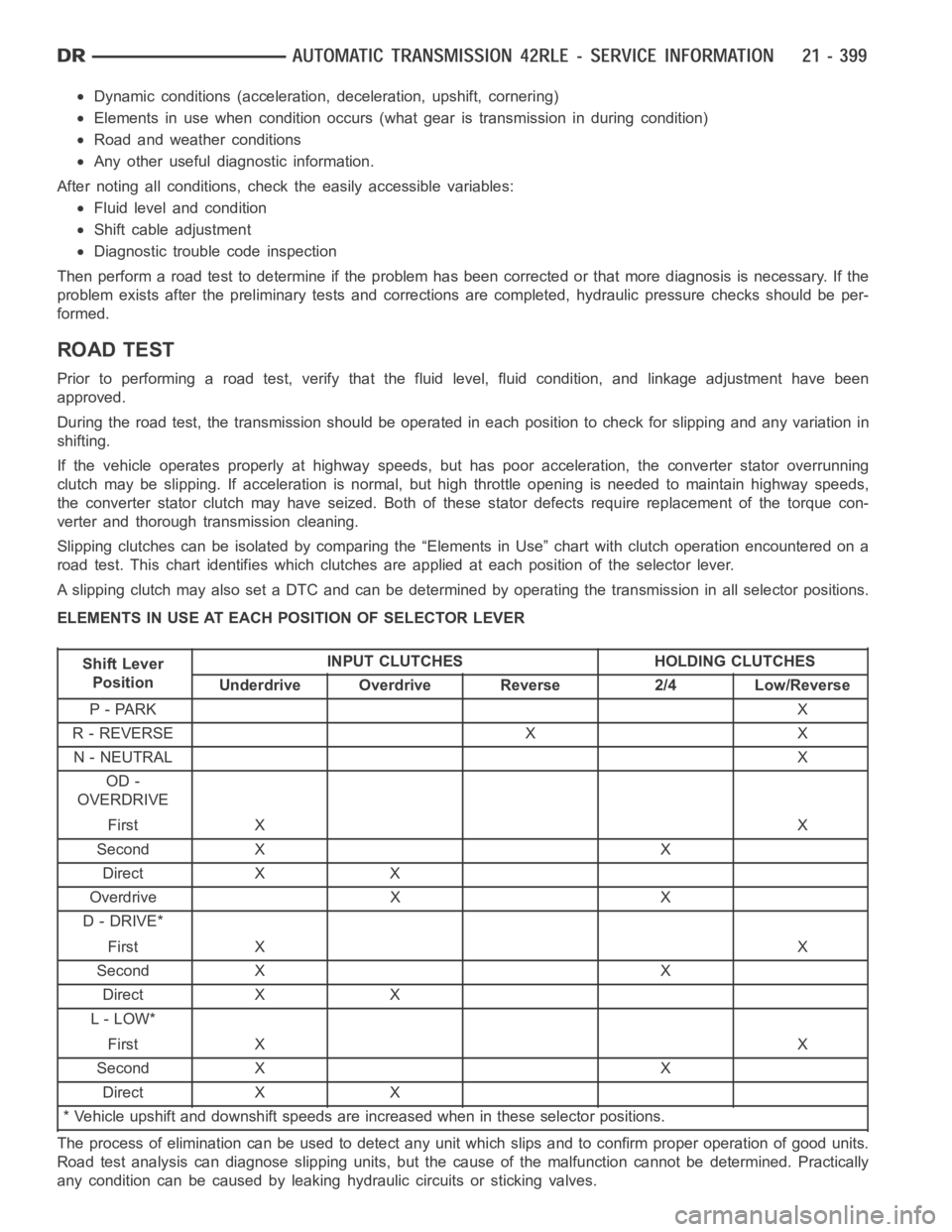
Slipping clutches can be isolated by comparing the “Elements in Use” chartwith clutch operation encountered on a
road test. This chart identifies which clutches are applied at each position of the selector lever.
A slipping clutch may also set a DTC and can be determined by operating the transmission in all selector positions.
ELEMENTS IN USE AT EACH POSITION OF SELECTOR LEVER
Shift Lever
PositionINPUT CLUTCHES HOLDING CLUTCHES
Underdrive Overdrive Reverse 2/4 Low/Reverse
P-PARKX
R-REVERSE X X
N - NEUTRALX
OD -
OVERDRIVE
First XX
Second X X
Direct X X
Overdrive X X
D - DRIVE*
First XX
Second X X
Direct X X
L-LOW*
First XX
Second X X
Direct X X
* Vehicle upshift and downshift speeds are increased when in these selector positions.
The process of elimination can be used to detect any unit which slips and to confirm proper operation of good units.
Road test analysis can diagnose slipping units, but the cause of the malfunction cannot be determined. Practically
any condition can be caused by leaking hydraulic circuits or sticking valves.
Page 2921 of 5267
HYDRAULIC PRESSURE TESTS
Pressure testing is a very important step in the diag-
nostic procedure. These tests usually reveal the cause
of most transmission problems.
Before performing pressure tests, be certain that fluid
level and condition, and shift cable adjustments have
been checked and approved. Fluid must be at operat-
ing temperature (150 to 200 degrees F.).
Install an engine tachometer, raise vehicle on hoist
which allows the wheels to turn, and position tachom-
eter so it can be read.
Using special adapters L-4559, attach 300 psi
gauge(s) C-3293SP to the port(s) required for test
being conducted.
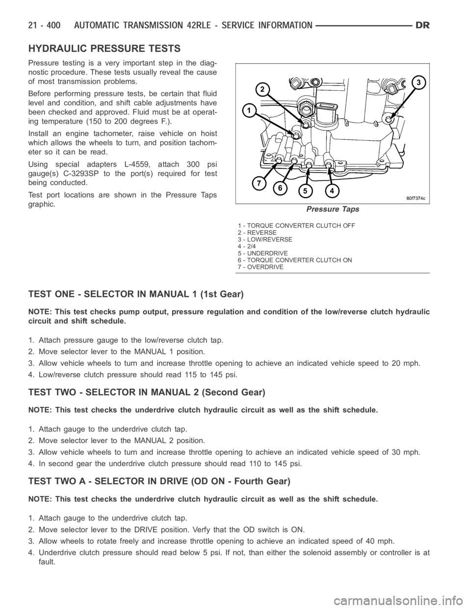
Test port locations are shown in the Pressure Taps
graphic.
TEST ONE - SELECTOR IN MANUAL 1 (1st Gear)
NOTE: This test checks pump output, pressure regulation and condition of the low/reverse clutch hydraulic
circuit and shift schedule.
1. Attach pressure gauge to the low/reverse clutch tap.
2. Move selector lever to the MANUAL 1 position.
3. Allow vehicle wheels to turn and increase throttle opening to achieve anindicatedvehiclespeedto20mph.
4. Low/reverse clutch pressure should read 115 to 145 psi.
TEST TWO - SELECTOR IN MANUAL 2 (Second Gear)
NOTE: This test checks the underdrive clutch hydraulic circuit as well as the shift schedule.
1. Attach gauge to the underdrive clutch tap.
2. Move selector lever to the MANUAL 2 position.
3. Allow vehicle wheels to turn and increase throttle opening to achieve anindicated vehicle speed of 30 mph.
4. In second gear the underdrive clutch pressure should read 110 to 145 psi.
TEST TWO A - SELECTOR IN DRIVE (OD ON - Fourth Gear)
NOTE: This test checks the underdrive clutch hydraulic circuit as well as the shift schedule.
1. Attach gauge to the underdrive clutch tap.
2. Move selector lever to the DRIVE position. Verfy that the OD switch is ON.
3. Allow wheels to rotate freely and increase throttle opening to achieve an indicated speed of 40 mph.
4. Underdrive clutch pressure should read below 5 psi. If not, than either the solenoid assembly or controller is at
fault.
Pressure Taps
1 - TORQUE CONVERTER CLUTCH OFF
2 - REVERSE
3 - LOW/REVERSE
4-2/4
5 - UNDERDRIVE
6 - TORQUE CONVERTER CLUTCH ON
7-OVERDRIVE
Page 2923 of 5267
5. Iftheunderdriveclutchpressureisgreaterthan5psiinStep4ofTestTwo-A, a defective solenoid/pressure
switch assembly or controller is the cause.
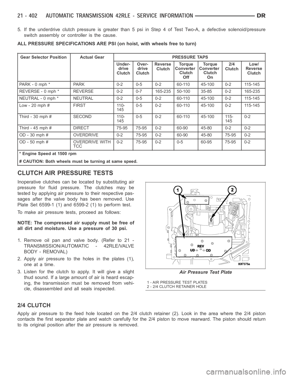
ALL PRESSURE SPECIFICATIONS ARE PSI (on hoist, with wheels free to turn)
Gear Selector Position Actual Gear PRESSURE TAPS
Under-
drive
ClutchOver-
drive
ClutchReverse
ClutchTo r q u e
Converter
Clutch
OffTo r q u e
Converter
Clutch
On2/4
ClutchLow/
Reverse
Clutch
PARK - 0 mph * PARK 0-2 0-5 0-2 60-110 45-100 0-2 115-145
REVERSE - 0 mph * REVERSE 0-2 0-7 165-235 50-100 35-85 0-2 165-235
NEUTRAL - 0 mph * NEUTRAL 0-2 0-5 0-2 60-110 45-100 0-2 115-145
Low - 20 mph # FIRST 110-
1450-5 0-2 60-110 45-100 0-2 115-145
Third-30mph# SECOND 110-
1450-5 0-2 60-110 45-100 115-
1450-2
Third - 45 mph # DIRECT 75-95 75-95 0-2 60-90 45-80 0-2 0-2
OD - 30 mph # OVERDRIVE 0-2 75-95 0-2 60-90 45-80 75-95 0-2
OD - 50 mph # OVERDRIVE WITH
TCC0-2 75-95 0-2 0-5 60-95 75-95 0-2
* Engine Speed at 1500 rpm
# CAUTION: Both wheels must be turning at same speed.
CLUTCH AIR PRESSURE TESTS
Inoperative clutches can be located by substituting air
pressure for fluid pressure. The clutches may be
tested by applying air pressure to their respective pas-
sages after the valve body has been removed. Use
Plate Set 6599-1 (1) and 6599-2 (1) to perform test.
To make air pressure tests, proceed as follows:
NOTE: The compressed air supply must be free of
all dirt and moisture. Use a pressure of 30 psi.
1. Remove oil pan and valve body. (Refer to 21 -
TRANSMISSION/AUTOMATIC - 42RLE/VALVE
BODY - REMOVAL)
2. Apply air pressure to the holes in the plates (1),
one at a time.
3. Listen for the clutch to apply. It will give a slight
thud sound. If a large amount of air is heard escap-
ing, the transmission must be removed from vehi-
cle, disassembled and all seals inspected.
2/4 CLUTCH
Apply air pressure to the feed hole located on the 2/4 clutch retainer (2). Look in the area where the 2/4 piston
contacts the first separator plate and watch carefully for the 2/4 piston tomoverearward.Thepistonshouldreturn
to its original position after the air pressure is removed.
Air Pressure Test Plate
1 - AIR PRESSURE TEST PLATES
2 - 2/4 CLUTCH RETAINER HOLE
Page 2924 of 5267
OVERDRIVE CLUTCH
Apply air pressure to the overdrive clutch apply passage and watch for the push/pull piston to move forward. The
piston should return to its starting position when the air pressure is removed.
REVERSE CLUTCH
Apply air pressure to the reverse clutch apply passage and watch for the push/pull piston to move rearward. The
piston should return to its starting position when the air pressure is removed.
LOW/REVERSE CLUTCH
Apply air pressure to the low/reverse clutch feed hole passage. Look in thearea where the low/reverse piston con-
tacts the first separator plate. Watch carefully for the piston to move forward. The piston should return to its original
position after the air pressure is removed.
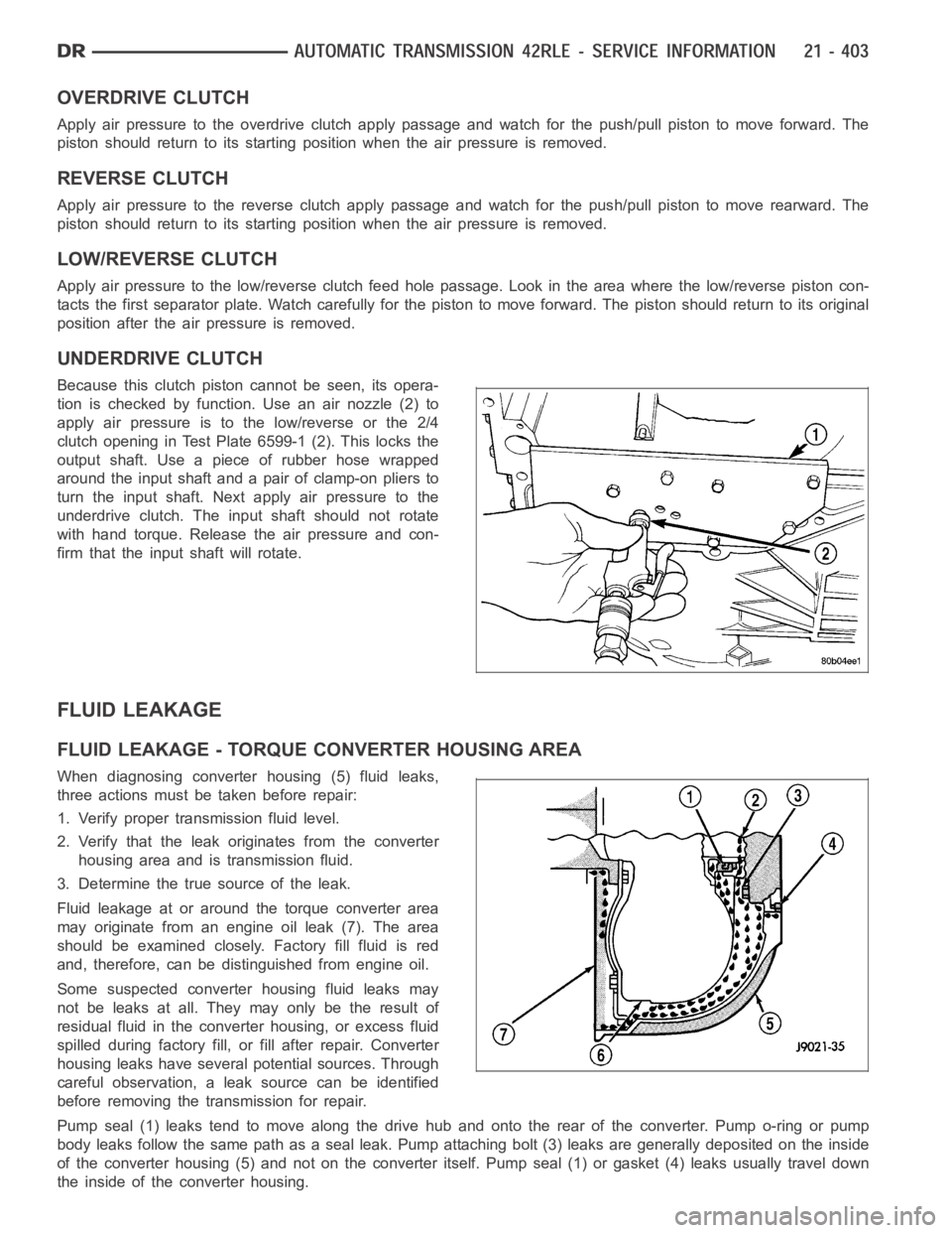
UNDERDRIVE CLUTCH
Because this clutch piston cannot be seen, its opera-
tion is checked by function. Use an air nozzle (2) to
apply air pressure is to the low/reverse or the 2/4
clutch opening in Test Plate 6599-1 (2). This locks the
output shaft. Use a piece of rubber hose wrapped
around the input shaft and a pair of clamp-on pliers to
turn the input shaft. Next apply air pressure to the
underdrive clutch. The input shaft should not rotate
with hand torque. Release the air pressure and con-
firm that the input shaft will rotate.
FLUID LEAKAGE
FLUID LEAKAGE - TORQUE CONVERTER HOUSING AREA
When diagnosing converter housing (5) fluid leaks,
three actions must be taken before repair:
1. Verify proper transmission fluid level.
2. Verify that the leak originates from the converter
housing area and is transmission fluid.
3. Determine the true source of the leak.
Fluid leakage at or around the torque converter area
may originate from an engine oil leak (7). The area
should be examined closely. Factory fill fluid is red
and, therefore, can be distinguished from engine oil.
Some suspected converter housing fluid leaks may
not be leaks at all. They may only be the result of
residual fluid in the converter housing, or excess fluid
spilled during factory fill, or fill after repair. Converter
housing leaks have several potential sources. Through
careful observation, a leak source can be identified
before removing the transmission for repair.
Pump seal (1) leaks tend to move along the drive hub and onto the rear of the converter. Pump o-ring or pump
body leaks follow the same path as a seal leak. Pump attaching bolt (3) leaksare generally deposited on the inside
of the converter housing (5) and not on the converter itself. Pump seal (1) or gasket (4) leaks usually travel down
the inside of the converter housing.
Page 2927 of 5267
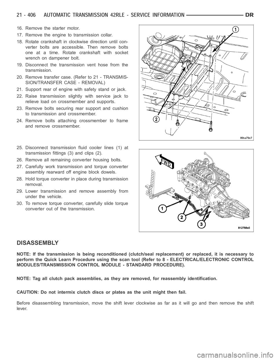
16. Remove the starter motor.
17. Remove the engine to transmission collar.
18. Rotate crankshaft in clockwise direction until con-
verter bolts are accessible. Then remove bolts
one at a time. Rotate crankshaft with socket
wrench on dampener bolt.
19. Disconnect the transmission vent hose from the
transmission.
20. Remove transfer case. (Refer to 21 - TRANSMIS-
SION/TRANSFER CASE - REMOVAL)
21. Support rear of engine with safety stand or jack.
22. Raise transmission slightly with service jack to
relieve load on crossmember and supports.
23. Remove bolts securing rear support and cushion
to transmission and crossmember.
24. Remove bolts attaching crossmember to frame
and remove crossmember.
25. Disconnect transmission fluid cooler lines (1) at
transmission fittings (3) and clips (2).
26. Remove all remaining converter housing bolts.
27. Carefully work transmission and torque converter
assembly rearward off engine block dowels.
28. Hold torque converter in place during transmission
removal.
29. Lower transmission and remove assembly from
under the vehicle.
30. To remove torque converter, carefully slide torque
converter out of the transmission.
DISASSEMBLY
NOTE: If the transmission is being reconditioned (clutch/seal replacement) or replaced, it is necessary to
perform the Quick Learn Procedure using the scan tool (Refer to 8 - ELECTRICAL/ELECTRONIC CONTROL
MODULES/TRANSMISSION CONTROL MODULE - STANDARD PROCEDURE).
NOTE: Tag all clutch pack assemblies, as they are removed, for reassembly identification.
CAUTION: Do not intermix clutch discs or plates as the unit might then fail.
Before disassembling transmission, move the shift lever clockwise as faras it will go and then remove the shift
lever.
Page 2972 of 5267
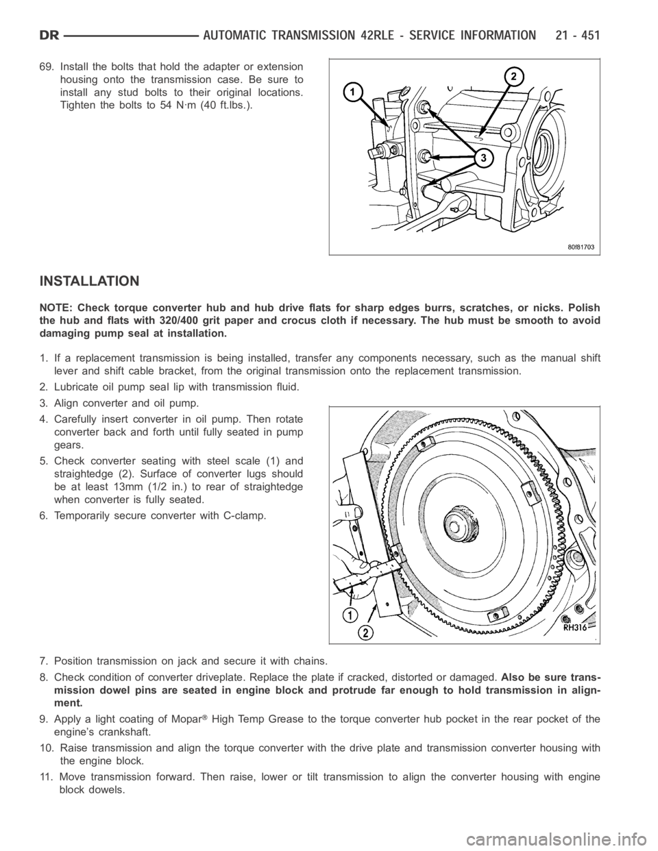
69. Install the bolts that hold the adapter or extension
housing onto the transmission case. Be sure to
install any stud bolts to their original locations.
Tighten the bolts to 54 Nꞏm (40 ft.lbs.).
INSTALLATION
NOTE: Check torque converter hub and hub drive flats for sharp edges burrs,scratches, or nicks. Polish
the hub and flats with 320/400 grit paper and crocus cloth if necessary. Thehub must be smooth to avoid
damaging pump seal at installation.
1. If a replacement transmission is being installed, transfer any components necessary, such as the manual shift
lever and shift cable bracket, from the original transmission onto the replacement transmission.
2. Lubricate oil pump seal lip with transmission fluid.
3. Align converter and oil pump.
4. Carefully insert converter in oil pump. Then rotate
converter back and forth until fully seated in pump
gears.
5. Check converter seating with steel scale (1) and
straightedge (2). Surface of converter lugs should
be at least 13mm (1/2 in.) to rear of straightedge
when converter is fully seated.
6. Temporarily secure converter with C-clamp.
7. Position transmission on jack and secure it with chains.
8. Check condition of converter driveplate. Replace the plate if cracked,distorted or damaged.Also be sure trans-
mission dowel pins are seated in engine block and protrude far enough to holdtransmissioninalign-
ment.
9. Apply a light coating of Mopar
High Temp Grease to the torque converter hub pocket in the rear pocket of the
engine’s crankshaft.
10. Raise transmission and align the torque converter with the drive plateand transmission converter housing with
the engine block.
11. Move transmission forward. Then raise, lower or tilt transmission to align the converter housing with engine
block dowels.
Page 2975 of 5267
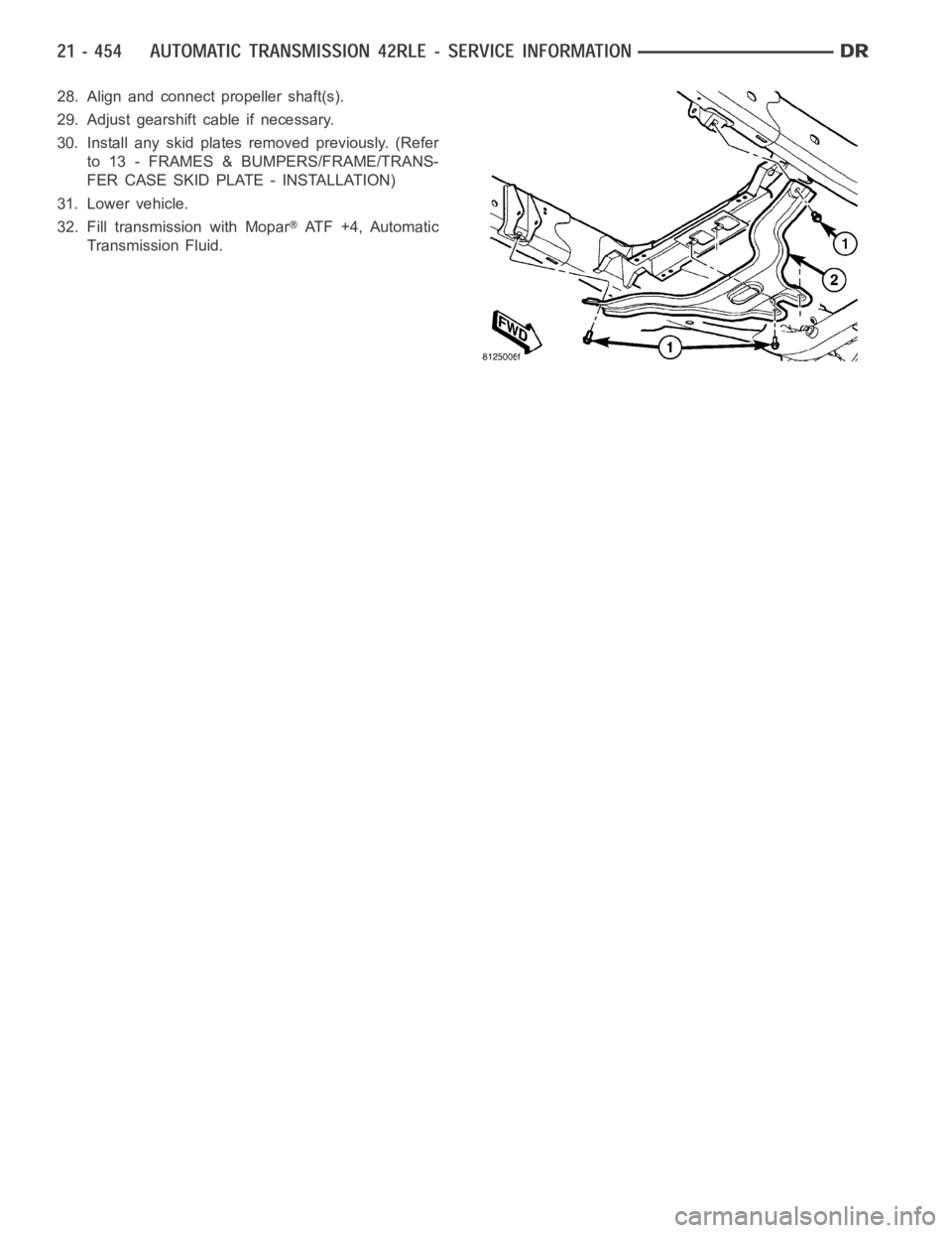
28. Align and connect propeller shaft(s).
29. Adjust gearshift cable if necessary.
30. Install any skid plates removed previously. (Refer
to 13 - FRAMES & BUMPERS/FRAME/TRANS-
FER CASE SKID PLATE - INSTALLATION)
31. Lower vehicle.
32. Fill transmission with Mopar
AT F + 4 , A u t o m a t i c
Transmission Fluid.
Page 3001 of 5267
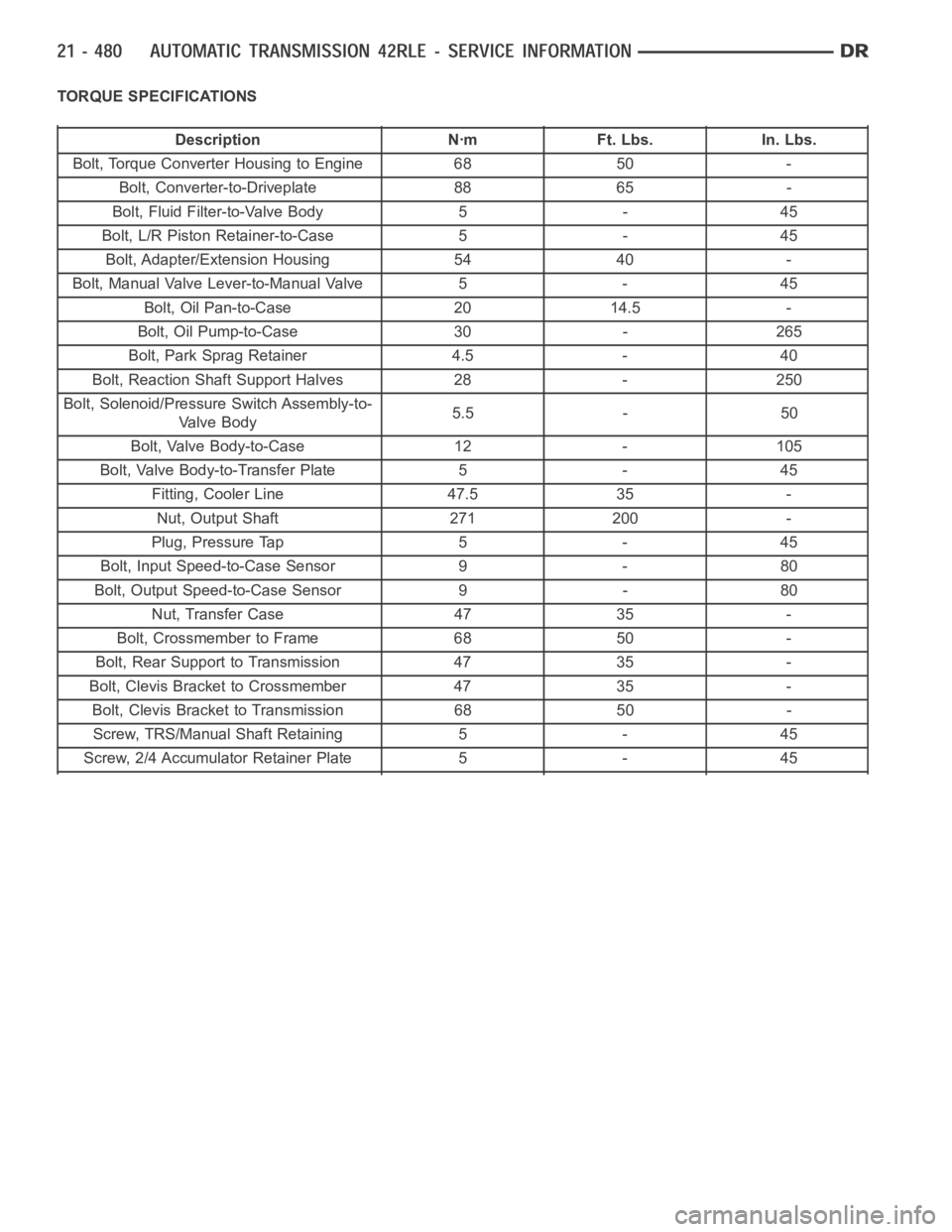
TORQUE SPECIFICATIONS
Description Nꞏm Ft. Lbs. In. Lbs.
Bolt, Torque Converter Housing to Engine 68 50 -
Bolt, Converter-to-Driveplate 88 65 -
Bolt, Fluid Filter-to-Valve Body 5 - 45
Bolt, L/R Piston Retainer-to-Case 5 - 45
Bolt, Adapter/Extension Housing 54 40 -
Bolt, Manual Valve Lever-to-Manual Valve 5 - 45
Bolt, Oil Pan-to-Case 20 14.5 -
Bolt, Oil Pump-to-Case 30 - 265
Bolt, Park Sprag Retainer 4.5 - 40
Bolt, Reaction Shaft Support Halves 28 - 250
Bolt, Solenoid/Pressure Switch Assembly-to-
Valve Body5.5 - 50
Bolt, Valve Body-to-Case 12 - 105
Bolt, Valve Body-to-Transfer Plate 5 - 45
Fitting, Cooler Line 47.5 35 -
Nut, Output Shaft 271 200 -
Plug, Pressure Tap 5 - 45
Bolt, Input Speed-to-Case Sensor 9 - 80
Bolt, Output Speed-to-Case Sensor 9 - 80
Nut, Transfer Case 47 35 -
Bolt, Crossmember to Frame 68 50 -
Bolt, Rear Support to Transmission 47 35 -
Bolt, Clevis Bracket to Crossmember 47 35 -
Bolt, Clevis Bracket to Transmission 68 50 -
Screw, TRS/Manual Shaft Retaining 5 - 45
Screw, 2/4 Accumulator Retainer Plate 5 - 45