Page 3051 of 5267
SENSOR-OUTPUT SPEED
DESCRIPTION
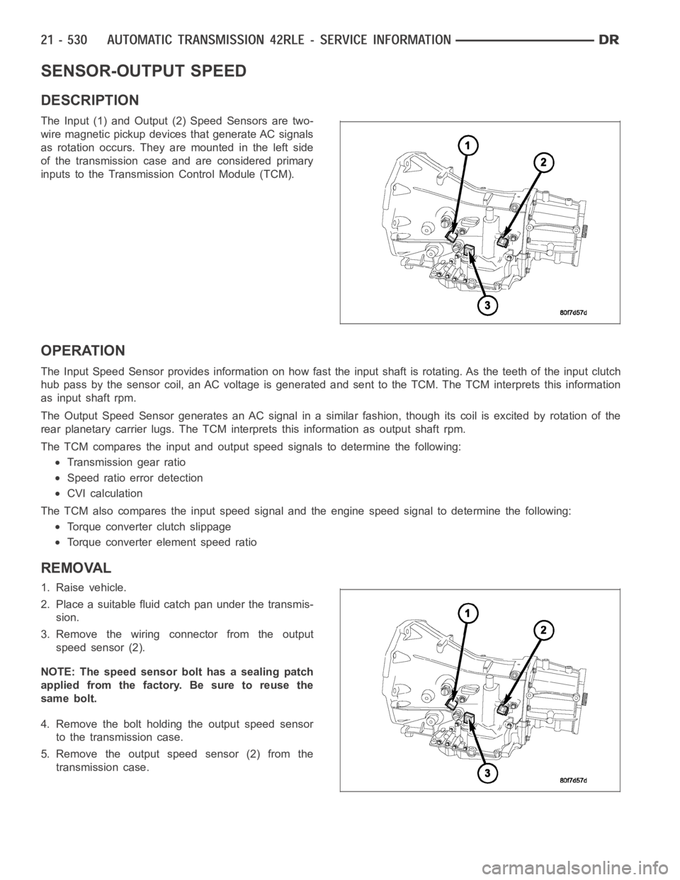
The Input (1) and Output (2) Speed Sensors are two-
wire magnetic pickup devices that generate AC signals
as rotation occurs. They are mounted in the left side
of the transmission case and are considered primary
inputs to the Transmission Control Module (TCM).
OPERATION
The Input Speed Sensor provides information on how fast the input shaft is rotating. As the teeth of the input clutch
hub pass by the sensor coil, an AC voltage is generated and sent to the TCM. The TCM interprets this information
as input shaft rpm.
The Output Speed Sensor generates an AC signal in a similar fashion, thoughitscoilisexcitedbyrotationofthe
rear planetary carrier lugs. The TCM interprets this information as outputshaftrpm.
The TCM compares the input and output speed signals to determine the following:
Transmission gear ratio
Speed ratio error detection
CVI calculation
The TCM also compares the input speed signal and the engine speed signal to determine the following:
Torque converter clutch slippage
Torque converter element speed ratio
REMOVAL
1. Raise vehicle.
2. Place a suitable fluid catch pan under the transmis-
sion.
3. Remove the wiring connector from the output
speed sensor (2).
NOTE: The speed sensor bolt has a sealing patch
applied from the factory. Be sure to reuse the
same bolt.
4. Remove the bolt holding the output speed sensor
to the transmission case.
5. Remove the output speed sensor (2) from the
transmission case.
Page 3052 of 5267
INSTALLATION
1. Install the output speed sensor (2) into the trans-
mission case.
NOTE: Before installing the speed sensor bolt, it
will be necessary to replenish the sealing patch on
the bolt using MOPAR
Lock & Seal Adhesive.
2. Install the bolt to hold the output speed sensor into
the transmission case. Tighten the bolt to 9 Nꞏm
(80 in.lbs.).
3. Install the wiring connector onto the output speed
sensor
4. Verify the transmission fluid level. Add fluid as nec-
essary.
5. Lower vehicle.
Page 3060 of 5267
ASSEMBLY-TRANSMISSION SOLENOID/PRESSURE SWITCH
DESCRIPTION
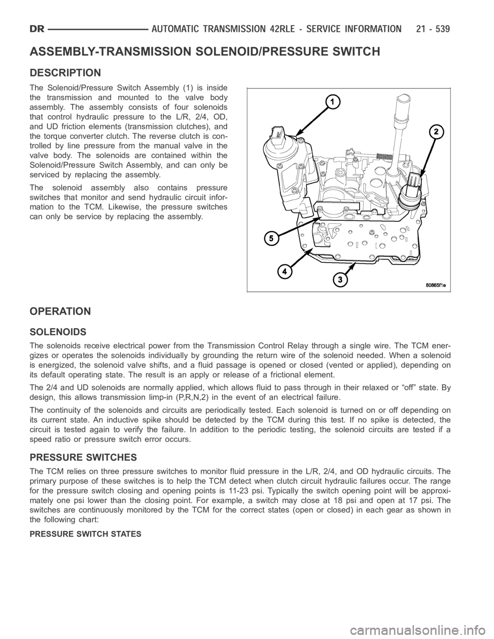
The Solenoid/Pressure Switch Assembly (1) is inside
the transmission and mounted to the valve body
assembly. The assembly consists of four solenoids
that control hydraulic pressure to the L/R, 2/4, OD,
and UD friction elements (transmission clutches), and
the torque converter clutch. The reverse clutch is con-
trolled by line pressure from the manual valve in the
valve body. The solenoids are contained within the
Solenoid/Pressure Switch Assembly, and can only be
serviced by replacing the assembly.
The solenoid assembly also contains pressure
switches that monitor and send hydraulic circuit infor-
mation to the TCM. Likewise, the pressure switches
can only be service by replacing the assembly.
OPERATION
SOLENOIDS
The solenoids receive electrical power from the Transmission Control Relay through a single wire. The TCM ener-
gizes or operates the solenoids individually by grounding the return wireof the solenoid needed. When a solenoid
is energized, the solenoid valve shifts, and a fluid passage is opened or closed (vented or applied), depending on
its default operating state. The result is an apply or release of a frictional element.
The 2/4 and UD solenoids are normally applied, which allows fluid to pass throughintheirrelaxedor“off”state.By
design, this allows transmission limp-in (P,R,N,2) in the event of an electrical failure.
The continuity of the solenoids and circuits are periodically tested. Each solenoid is turned on or off depending on
its current state. An inductive spike should be detected by the TCM during this test. If no spike is detected, the
circuit is tested again to verify the failure. In addition to the periodic testing, the solenoid circuits are tested if a
speed ratio or pressure switch error occurs.
PRESSURE SWITCHES
The TCM relies on three pressure switches to monitor fluid pressure in the L/R, 2/4, and OD hydraulic circuits. The
primary purpose of these switches is to help the TCM detect when clutch circuit hydraulic failures occur. The range
for the pressure switch closing and opening points is 11-23 psi. Typicallythe switch opening point will be approxi-
mately one psi lower than the closing point. For example, a switch may closeat 18 psi and open at 17 psi. The
switches are continuously monitored by the TCM for the correct states (open or closed) in each gear as shown in
the following chart:
PRESSURE SWITCH STATES
Page 3063 of 5267
CONVERTER-TORQUE
DESCRIPTION
The torque converter is a hydraulic device that cou-
ples the engine crankshaft to the transmission. The
torque converter consists of an outer shell with an
internal turbine (1), a stator (4), an overrunning clutch,
an impeller (2) and an electronically applied converter
clutch (6). The converterclutch provides reduced
engine speed and greater fuel economy when
engaged. Clutch engagement also provides reduced
transmission fluid temperatures. The torque converter
hub drives the transmission oil (fluid) pump.
The torque converter is a sealed, welded unit that is
not repairable and is serviced as an assembly.
CAUTION: The torque converter must be replaced
if a transmission failure resulted in large amounts
of metal or fiber contamination in the fluid.
Page 3067 of 5267
TORQUE CONVERTER CLUTCH (TCC)
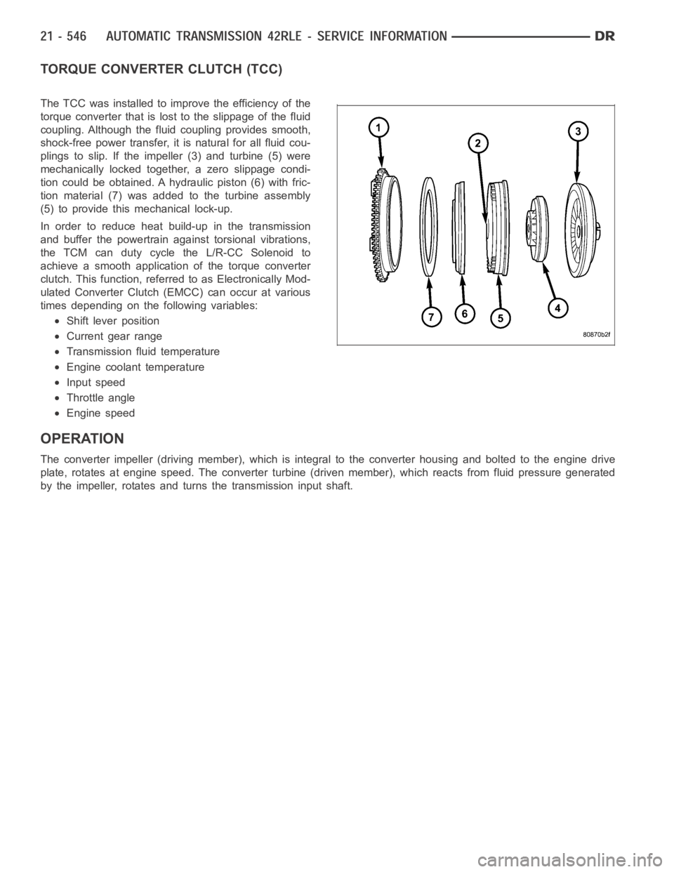
The TCC was installed to improve the efficiency of the
torque converter that is lost to the slippage of the fluid
coupling. Although the fluid coupling provides smooth,
shock-free power transfer, it is natural for all fluid cou-
plings to slip. If the impeller (3) and turbine (5) were
mechanically locked together, a zero slippage condi-
tion could be obtained. A hydraulic piston (6) with fric-
tion material (7) was added to the turbine assembly
(5) to provide this mechanical lock-up.
In order to reduce heat build-up in the transmission
and buffer the powertrain against torsional vibrations,
the TCM can duty cycle the L/R-CC Solenoid to
achieve a smooth application of the torque converter
clutch. This function, referred to as Electronically Mod-
ulated Converter Clutch (EMCC) can occur at various
times depending on the following variables:
Shift lever position
Current gear range
Transmission fluid temperature
Engine coolant temperature
Input speed
Throttle angle
Engine speed
OPERATION
The converter impeller (driving member), which is integral to the converter housing and bolted to the engine drive
plate, rotates at engine speed. The converter turbine (driven member), which reacts from fluid pressure generated
by the impeller, rotates and turns the transmission input shaft.
Page 3070 of 5267
4. Separate the torque converter from the transmission.
INSTALLATION
NOTE: Check converter hub and drive notches for sharp edges, burrs, scratches, or nicks. Polish the hub
and notches with 320/400 grit paper or crocus cloth if necessary. The hub must be smooth to avoid dam-
aging the pump seal at installation.
1. Lubricate oil pump seal lip with transmission fluid.
2. Place torque converter in position on transmission.
CAUTION: Do not damage oil pump seal or bush-
ing while inserting torqueconverterintothefront
of the transmission.
3. Align torque converter to oil pump seal opening.
4. Insert torque converter hub into oil pump.
5. While pushing torque converter inward, rotate con-
verter until converter is fully seated in the oil pump
gears.
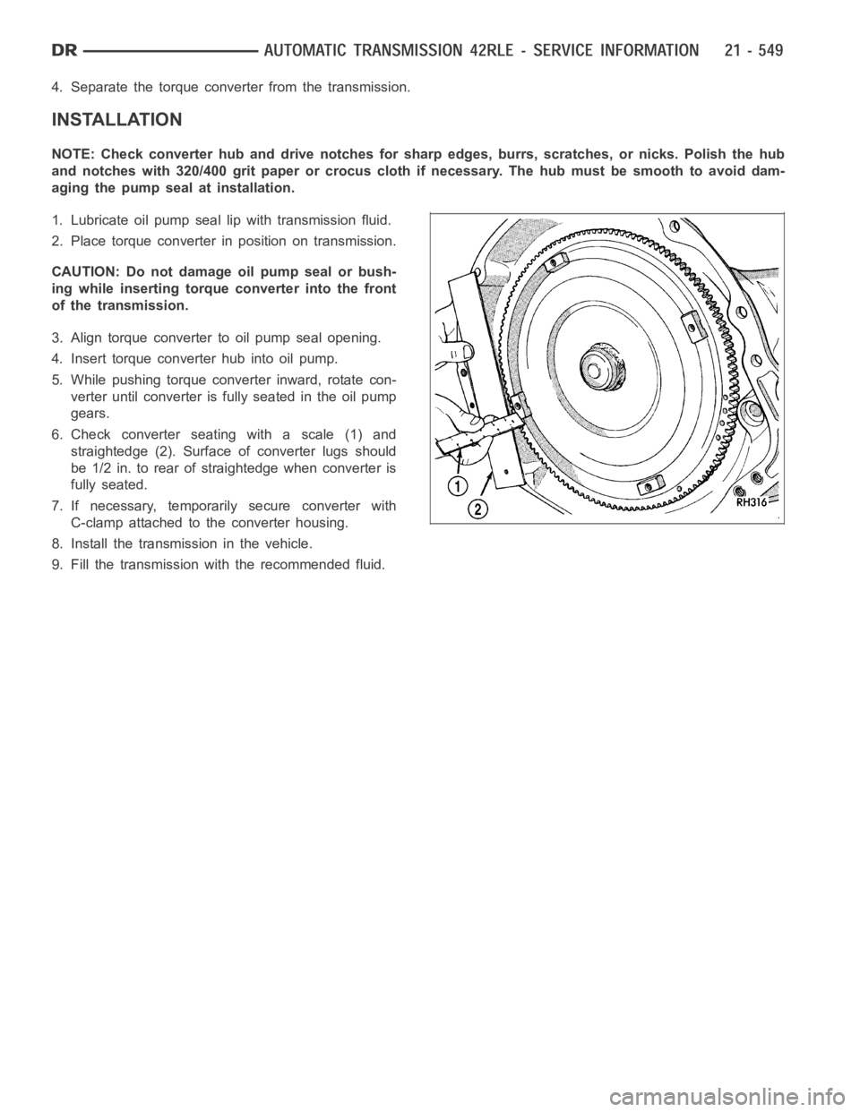
6. Check converter seating with a scale (1) and
straightedge (2). Surface of converter lugs should
be 1/2 in. to rear of straightedge when converter is
fully seated.
7. If necessary, temporarily secure converter with
C-clamp attached to the converter housing.
8. Install the transmission in the vehicle.
9. Fill the transmission with the recommended fluid.
Page 3077 of 5267
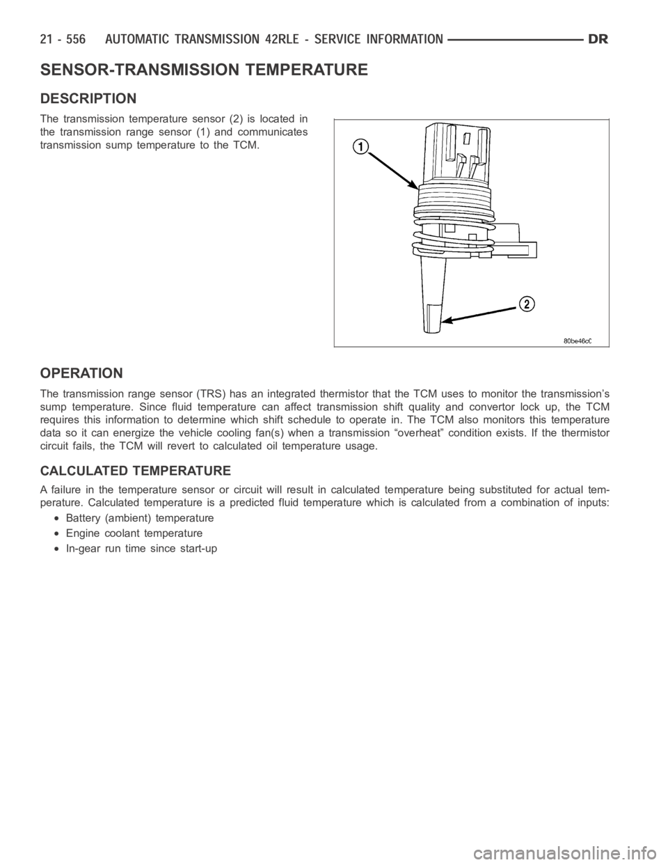
SENSOR-TRANSMISSION TEMPERATURE
DESCRIPTION
The transmission temperature sensor (2) is located in
the transmission range sensor (1) and communicates
transmission sump temperature to the TCM.
OPERATION
The transmission range sensor (TRS) has an integrated thermistor that theTCM uses to monitor the transmission’s
sump temperature. Since fluid temperature can affect transmission shiftquality and convertor lock up, the TCM
requires this information to determine which shift schedule to operate in. The TCM also monitors this temperature
data so it can energize the vehicle cooling fan(s) when a transmission “overheat” condition exists. If the thermistor
circuit fails, the TCM will revert to calculated oil temperature usage.
CALCULATED TEMPERATURE
A failure in the temperature sensor or circuit will result in calculated temperature being substituted for actual tem-
perature. Calculated temperature is a predicted fluid temperature whichis calculated from a combination of inputs:
Battery (ambient) temperature
Engine coolant temperature
In-gear run time since start-up
Page 3083 of 5267
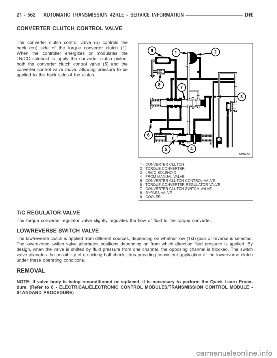
CONVERTER CLUTCH CONTROL VALVE
The converter clutch control valve (5) controls the
back (on) side of the torque converter clutch (1).
When the controller energizes or modulates the
LR/CC solenoid to apply the converter clutch piston,
both the converter clutch control valve (5) and the
converter control valve move, allowing pressure to be
applied to the back side of the clutch.
T/C REGULATOR VALVE
The torque converter regulator valve slightly regulates the flow of fluidto the torque converter.
LOW/REVERSE SWITCH VALVE
The low/reverse clutch is applied from different sources, depending on whether low (1st) gear or reverse is selected.
The low/reverse switch valve alternates positions depending on from which direction fluid pressure is applied. By
design, when the valve is shifted by fluid pressure from one channel, the opposing channel is blocked. The switch
valve alienates the possibility of a sticking ball check, thus providing consistent application of the low/reverse clutch
under these operating conditions.
REMOVAL
NOTE: If valve body is being reconditioned or replaced, it is necessary to perform the Quick Learn Proce-
dure. (Refer to 8 - ELECTRICAL/ELECTRONIC CONTROL MODULES/TRANSMISSIONCONTROL MODULE -
STANDARD PROCEDURE)
1 - CONVERTER CLUTCH
2 - TORQUE CONVERTER
3 - LR/CC SOLENOID
4 - FROM MANUAL VALVE
5 - CONVERTER CLUTCH CONTROL VALVE
6 - TORQUE CONVERTER REGULATOR VALVE
7 - CONVERTER CLUTCH SWITCH VALVE
8 - BYPASS VALVE
9 - COOLER