2006 DODGE RAM SRT-10 Crankshaft
[x] Cancel search: CrankshaftPage 1987 of 5267
REMOVAL
1. Disconnect the battery cables.
2. Remove the cylinder head (Refer to 9 - ENGINE/CYLINDER HEAD - REMOVAL).
3. Remove the oil pan and suction tube (Refer to 9 - ENGINE/LUBRICATION/OILPA N - R E M O VA L ) .
4. Remove bolts and the block stiffener.
5. Using Miller Tool 7471-B crankshaft barring tool, rotate the crankshaft so all of the pistons are below TDC.
6. Before removing the piston(s) from the bore(s):
a. Remove any carbon ridge formations or deposits at the top of the bore witha dull scraper or soft wire brush.
b. If cylinder bore wear ridges are found, use a ridge reamer to cut the ridgefrom the bore. DO NOT remove
more metal than necessaryto remove the ridge.
7. Remove the J-jet cooling nozzles.
NOTE: If cylinders have ridges, the cylinders are oversize and will more than likely need boring.
8. Using a hammer and steel stamp, stamp the cylinder number in the top of eachpiston.Thefrontofthepiston
is identified by a stamping on the top of the piston. DO NOT stamp in the outside 5 mm (.197 in.) of the piston
diameter. DO NOT stamp over the piston pin.
9. Mark the connecting rod and cap with the corresponding cylinder numbers.
10. Remove the connecting rod bolts and rod caps. Use care so the cylinder bores and connecting rods are not
damaged.
11. Use a hammer handle or similar object to push the piston and connecting rod through the cylinder bore.
12. Store the piston/rod assemblies in a rack.
CLEANING—PISTON AND CONNECTING ROD
CAUTION: DO NOT use bead blast to clean the pistons. DO NOT clean the pistonsandrodsinanacidtank.
PISTON
Clean the pistons and pins in a suitable solvent, rinse in hot water and blowdry with compressed air. Soaking the
pistons over night will loosen most of the carbon build up. De-carbon the ringgrooveswithabrokenpistonringand
again clean the pistons in solvent. Rinse in hot water and blow dry with compressed air.
CONNECTING ROD
Clean the connecting rods in a suitable solvent, rinse in hot water and blowdry with compressed air.
INSPECTION
INSPECTION - PISTONS
PISTON SKIRT DIAMETER (MIN.)
101.775 mm (4.006 in. )
Inspect the pistons for damage and excessive wear. Check top of the piston,ring grooves, skirt and pin bore. Mea-
sure the piston skirt diameter. If the piston is out of limits, replace the piston.
Page 1989 of 5267
INSPECTION - CONNECTING ROD
Inspect the connecting rod for damage and wear. The
I-Beam section of the connecting rod cannot have
dents or other damage. Damage to this part can
cause stress risers which will progress to breakage.
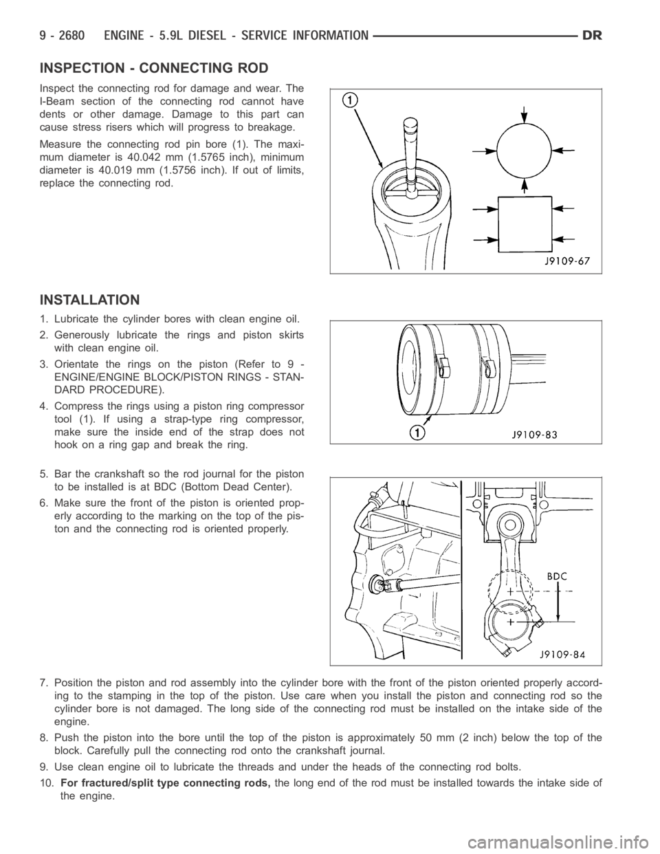
Measure the connecting rod pin bore (1). The maxi-
mum diameter is 40.042 mm (1.5765 inch), minimum
diameter is 40.019 mm (1.5756 inch). If out of limits,
replace the connecting rod.
INSTALLATION
1. Lubricate the cylinder bores with clean engine oil.
2. Generously lubricate the rings and piston skirts
with clean engine oil.
3. Orientate the rings on the piston (Refer to 9 -
ENGINE/ENGINE BLOCK/PISTON RINGS - STAN-
DARD PROCEDURE).
4. Compress the rings using a piston ring compressor
tool(1).Ifusingastrap-typeringcompressor,
make sure the inside end of the strap does not
hook on a ring gap and break the ring.
5. Bar the crankshaft so the rod journal for the piston
to be installed is at BDC(Bottom Dead Center).
6. Make sure the front of the piston is oriented prop-
erly according to the marking on the top of the pis-
ton and the connecting rod is oriented properly.
7. Position the piston and rod assemblyinto the cylinder bore with the front of the piston oriented properly accord-
ing to the stamping in the top of the piston. Use care when you install the piston and connecting rod so the
cylinder bore is not damaged. The long side of the connecting rod must be installed on the intake side of the
engine.
8. Push the piston into the bore until the top of the piston is approximately50 mm (2 inch) below the top of the
block. Carefully pull the connecting rod onto the crankshaft journal.
9. Use clean engine oil to lubricate the threads and under the heads of the connecting rod bolts.
10.For fractured/split type connecting rods,thelongendoftherodmustbeinstalledtowardstheintakesideof
the engine.
Page 1990 of 5267
a. The connecting rod split/face mustface toward the same side as the piston notch feature on the skirt. The
split face will face toward the exhaust side of the engine if properly installed.
11. Install the rod cap and bolts to the connecting rod. Tighten the connecting rod bolts evenly in 3 steps.
Tighten the bolts to 30 Nꞏm (22 ft. lbs.) torque.
Tighten the bolts to 60 Nꞏm (44 ft. lbs.) torque.
Rotate 60° clockwise.
12. The crankshaft must rotate freely. Check for freedom of rotation as thecaps are installed. If the crankshaft does
not rotate freely, check the installation of the rod bearing and the bearingsize.
13. Measure the side clearance between the connecting rod and the crankshaft. DO NOT measure the clearance
between the cap and crankshaft.
14. Install J-jet piston cooling nozzles.
15. Install block stiffener. Torque to 43 Nꞏm (32 ft. lbs.).
16. Install the suction tube and oil pan (Refer to 9 - ENGINE/LUBRICATION/OIL PAN - INSTALLATION).
17. Install the cylinder head onto the engine (Refer to 9 - ENGINE/CYLINDERHEAD - INSTALLATION).
18. Install a new filter and fill the crankcase with new engine oil.Prefill the filter with clean oil.
19. Connect the battery negative cables and start engine.
Page 1993 of 5267
DAMPER - CRANKSHAFT
REMOVAL
1. Remove the accessory drive belt (Refer to 7 - COOLING/ACCESSORY DRIVE/DRIVE BELTS - REMOVAL).
2. Remove the four (4) damper to crankshaft bolts and remove damper and speed indicator ring.
INSPECTION
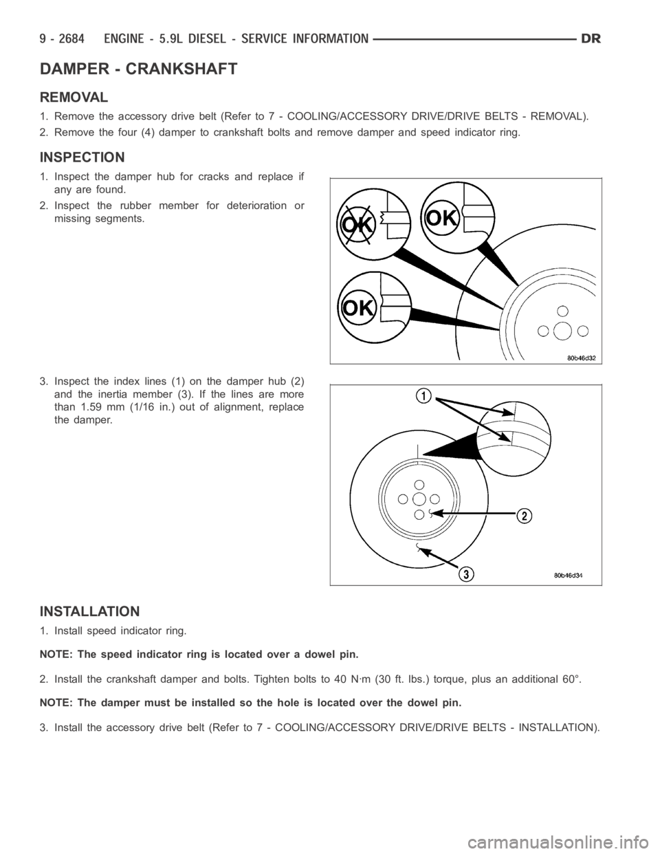
1. Inspect the damper hub for cracks and replace if
any are found.
2. Inspect the rubber member for deterioration or
missing segments.
3. Inspect the index lines (1) on the damper hub (2)
and the inertia member (3). If the lines are more
than 1.59 mm (1/16 in.) out of alignment, replace
the damper.
INSTALLATION
1. Install speed indicator ring.
NOTE: The speed indicator ring is located over a dowel pin.
2. Install the crankshaft damper and bolts. Tighten bolts to 40 Nꞏm (30 ft. lbs.) torque, plus an additional 60°.
NOTE: The damper must be installed so the hole is located over the dowel pin.
3. Install the accessory drive belt (Refer to 7 - COOLING/ACCESSORY DRIVE/DRIVE BELTS - INSTALLATION).
Page 1999 of 5267
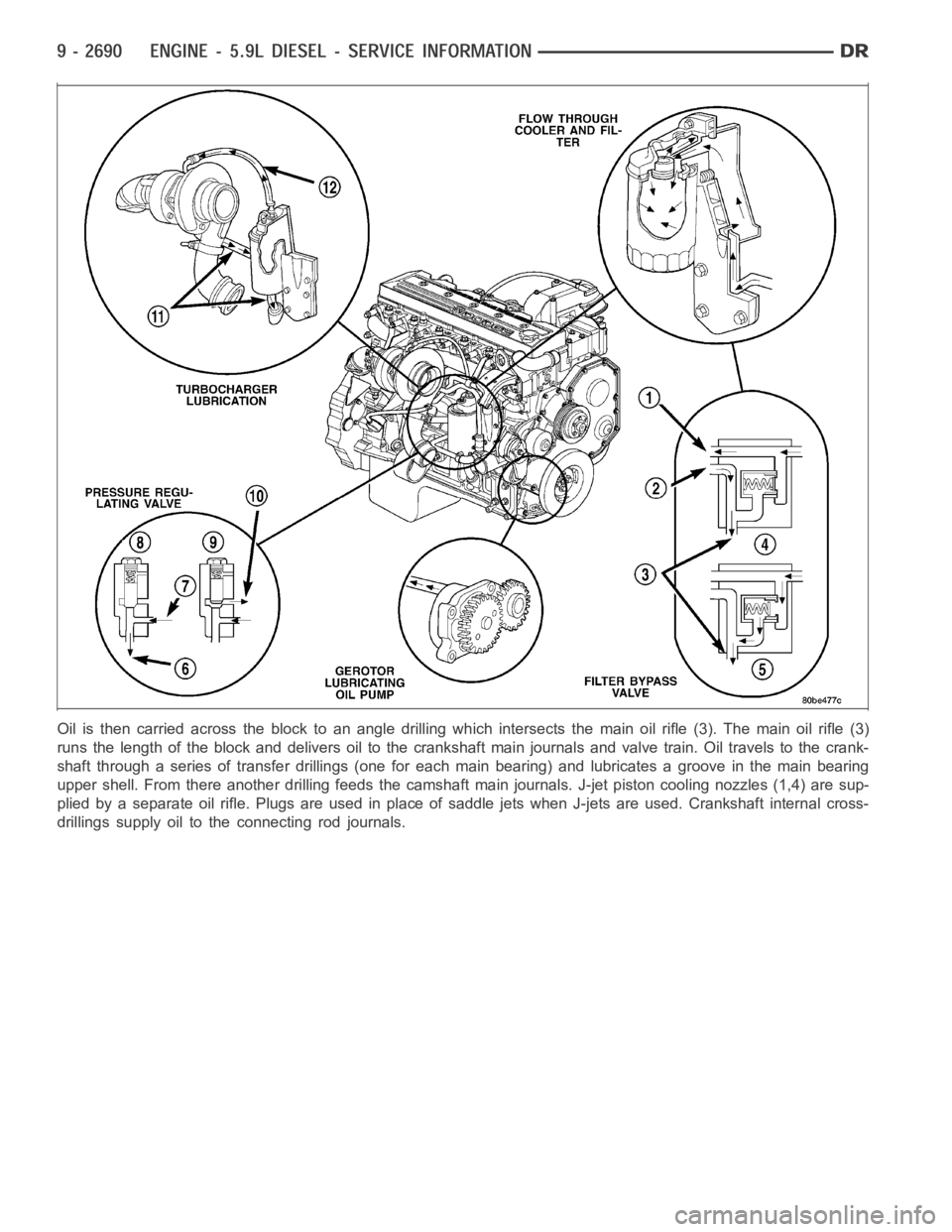
Oil is then carried across the block toan angle drilling which intersects the main oil rifle (3). The main oil rifle (3)
runs the length of the block and delivers oil to the crankshaft main journals and valve train. Oil travels to the crank-
shaft through a series of transfer drillings (one for each main bearing) and lubricates a groove in the main bearing
upper shell. From there another drilling feeds the camshaft main journals. J-jet piston cooling nozzles (1,4) are sup-
plied by a separate oil rifle. Plugs are used in place of saddle jets when J-jets are used. Crankshaft internal cross-
drillings supply oil to the connecting rod journals.
Page 2005 of 5267
PA N - E N G I N E O I L
REMOVAL
1. Disconnect the battery negative cables.
2. Install engine support fixture # 8534.
3. Raise vehicle on hoist.
4. Disconnect starter cables from starter motor.
5. Remove transmission and transfer case (if equipped).
6. Remove flywheel or flexplate.
7. Remove starter motor (Refer to 8 - ELECTRICAL/STARTING/STARTER MOTOR -REMOVAL) and transmission
adapter plate assembly.
WARNING: HOT OIL CAN CAUSE PERSONAL INJURY.
8. Drain the engine oil (Refer to 9 - ENGINE/LUBRICATION/OIL - STANDARD PROCEDURE).
9. Install the oil pan drain plug if sealing surface is not damaged and tighten to 50 Nꞏm (37 ft. lbs.) torque.
10. Remove oil pan bolts, break the pan to block seal, and lower pan slightlyandremoveoilsuctiontubefasteners.
11. Remove oil pan and suction tube.
CLEANING
Remove all gasket material from the oil pan and cylinder block sealing surfaces. Extra effort may be required
around T-joint areas. Clean oil pan and flush suction tube with a suitable solvent.
INSPECTION
Inspect the oil pan, suction tube, and tube braces for cracks and damage. Replace any defective component.
Inspect the oil drain plug and drain hole threads. Inspect the oil pan sealing surface for straightness. Repair any
minor imperfections with a ball-peen hammer. Do not attempt to repair an oil pan by welding.
INSTALLATION
1. Fill the T-joint between the pan rail/gear housing and pan rail/rear seal retainer with sealant. Use MoparSilicone
Rubber Adhesive Sealant or equivalent.
2. Place suction tube in oil pan and guide them into place. Slide oil pan gasket into postion.Using a new tube to
block gasket, install and tighten the suction tube bolts by hand. Startingwith the oil pump inlet bolts, tighten the
bolts to 24 Nꞏm (18 ft. lbs.) torque. Tighten the remaining tube brace boltsto 43 Nꞏm (32 ft. lbs.) torque.
3. Starting in the center and working outward, tighten the oil pan bolts to 28Nꞏm(21ft.lbs.)torque.
4. Install the flywheel housing assembly with the starter motor attached and tighten bolts to 77 Nꞏm (57 ft. lbs.)
torque.
5. Connect starter motor cables.
NOTE: A new clamping ring must be used on early or late builds, automatic or manual. Do not reuse clamp-
ing ring.
6. Install the flywheel to crankshaft adapter. Torque to 137 Nꞏm (101 ft. lbs.).
7. Install transmission and transfer case (if equipped).
8. Lower vehicle.
9. Remove the engine support fixture # 8534.
10. Install battery negative cables.
11. Fill the crankcase with new engine oil.
12. Start engine and check for leaks. Stop engine, check oil level, and adjust, if necessary.
Page 2008 of 5267
PUMP - ENGINE OIL
REMOVAL
1. Disconnect the battery negative cables.
2. Remove fan/drive assembly (Refer to 7 - COOL-
ING/ENGINE/RADIATOR FAN - REMOVAL).
3. Remove the accessory drive belt (Refer to 7 -
COOLING/ACCESSORY DRIVE/DRIVE BELTS -
REMOVAL).
4. Remove the fan support/hub assembly.
5. Remove crankshaft damper (Refer to 9 - ENGINE/
ENGINE BLOCK/VIBRATION DAMPER -
REMOVAL) and speed indicator ring.
6. Remove power steering pump.
7. Remove accessory drive belt tensioner.
8. Remove the gear housing cover (Refer to 9 -
ENGINE/VALVE TIMING/GEAR HOUSING COVER
- REMOVAL).
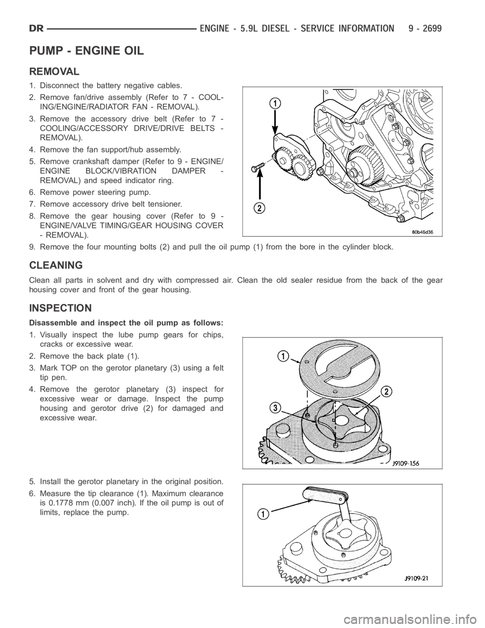
9. Remove the four mounting bolts (2) and pull the oil pump (1) from the bore in the cylinder block.
CLEANING
Clean all parts in solvent and dry with compressed air. Clean the old sealerresidue from the back of the gear
housing cover and front of the gear housing.
INSPECTION
Disassemble and inspect the oil pump as follows:
1. Visually inspect the lube pump gears for chips,
cracks or excessive wear.
2. Remove the back plate (1).
3. Mark TOP on the gerotor planetary (3) using a felt
tip pen.
4. Remove the gerotor planetary (3) inspect for
excessive wear or damage. Inspect the pump
housing and gerotor drive (2) for damaged and
excessive wear.
5. Install the gerotor planetary in the original position.
6. Measure the tip clearance (1). Maximum clearance
is 0.1778 mm (0.007 inch). If the oil pump is out of
limits, replace the pump.
Page 2010 of 5267
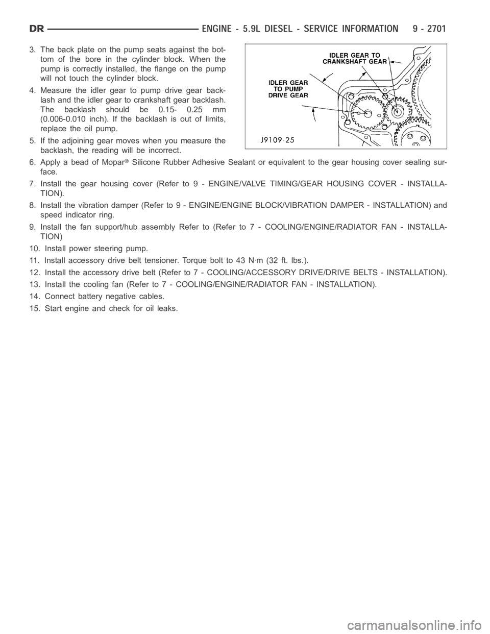
3. The back plate on the pump seats against the bot-
tom of the bore in the cylinder block. When the
pump is correctly installed, the flange on the pump
will not touch the cylinder block.
4. Measure the idler gear to pump drive gear back-
lash and the idler gear to crankshaft gear backlash.
The backlash should be 0.15- 0.25 mm
(0.006-0.010 inch). If the backlash is out of limits,
replace the oil pump.
5. If the adjoining gear moves when you measure the
backlash, the reading will be incorrect.
6. Apply a bead of Mopar
Silicone Rubber Adhesive Sealant or equivalent to the gear housing cover sealing sur-
face.
7. Install the gear housing cover (Refer to 9 - ENGINE/VALVE TIMING/GEAR HOUSING COVER - INSTALLA-
TION).
8. Install the vibration damper (Refer to 9 - ENGINE/ENGINE BLOCK/VIBRATION DAMPER - INSTALLATION) and
speed indicator ring.
9. Install the fan support/hub assemblyRefer to (Refer to 7 - COOLING/ENGINE/RADIATOR FAN - INSTALLA-
TION)
10. Install power steering pump.
11. Install accessory drive belt tensioner. Torque bolt to 43 Nꞏm (32 ft. lbs.).
12. Install the accessory drive belt (Refer to 7 - COOLING/ACCESSORY DRIVE/DRIVE BELTS - INSTALLATION).
13. Install the cooling fan (Refer to 7 - COOLING/ENGINE/RADIATOR FAN - INSTALLATION).
14. Connect battery negative cables.
15. Start engine and check for oil leaks.