2006 DODGE RAM SRT-10 Crankshaft
[x] Cancel search: CrankshaftPage 1914 of 5267
3. Place a shop towel around the fuel injectors to catch any fluid that may possibly be under pressure in the cyl-
inder head. Remove the fuel injectors (Refer to 14 - FUEL SYSTEM/FUEL INJECTION/FUEL INJECTOR -
REMOVAL).
4. With all injectors removed, rotatethe crankshaft using the crankshaftbarring tool (PN 7471–B).
5. Identify the fluid in the cylinders (coolant, fuel, oil, etc.).
6. Be sure all fluid has been removed from the cylinders.
7. Repair engine or components as necessary to prevent this problem from occurring again.
8. Squirt a small amount of engine oil into the cylinders to lubricate the walls. This will prevent damage on restart.
9. Install fuel injectors (Refer to 14 - FUEL SYSTEM/FUEL INJECTION/FUEL INJECTOR - INSTALLATION).
10. Drain engine oil. Remove and discard the oil filter (Refer to 9 - ENGINE/LUBRICATION/OIL FILTER -
REMOVAL).
11. Installthedrainplug.Tightentheplugto50Nꞏm(37ft.lbs.)torque.
12. Install a new oil filter (Refer to 9 - ENGINE/LUBRICATION/OIL FILTER - INSTALLATION).
13. Fill engine crankcase with the specified amount and grade of oil (Referto LUBRICATION & MAINTENANCE/
FLUID TYPES - SPECIFICATIONS).
14. Connect the negative cable(s) to the battery.
15. Start the engine and check for any leaks.
REMOVAL - ENGINE
1. Disconnect both battery negative cables.
2. Disconnect engine grid heater harness at grid
heater relays.
3. Disconnect electrical connections from rear of alter-
nator.
4. Recover A/C refrigerant. (Refer to 24 - HEATING &
AIR CONDITIONING/PLUMBING - STANDARD
PROCEDURE).
5. Raise vehicle on a hoist.
6. Drain engine coolant (Refer to 7 - COOLING -
STANDARD PROCEDURE).
7. Remove engine oil drain plug and drain engine oil.
8. Reinstall drain plug. Tighten to 50 Nꞏm (37 ft. lbs.)
torque.
9. Lower the vehicle.
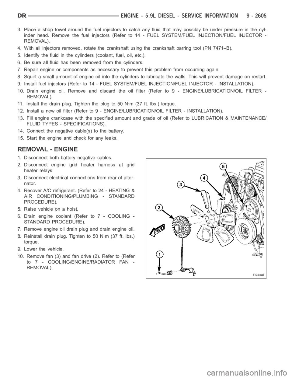
10. Remove fan (3) and fan drive (2). Refer to (Refer
to 7 - COOLING/ENGINE/RADIATOR FAN -
REMOVAL).
Page 1923 of 5267
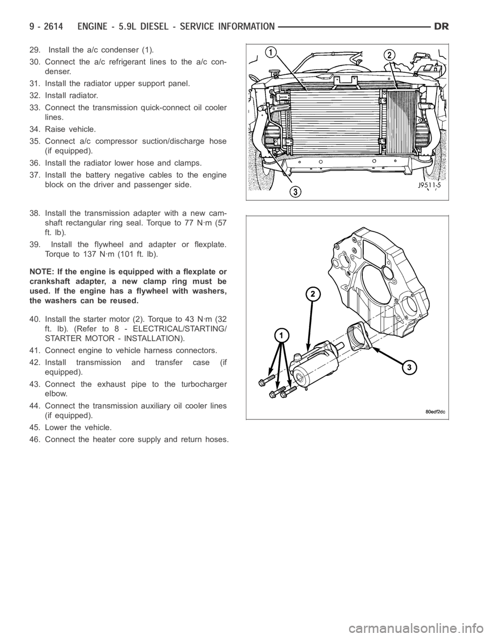
29. Install the a/c condenser (1).
30. Connect the a/c refrigerant lines to the a/c con-
denser.
31. Install the radiator upper support panel.
32. Install radiator.
33. Connect the transmission quick-connect oil cooler
lines.
34. Raise vehicle.
35. Connect a/c compressor suction/discharge hose
(if equipped).
36. Install the radiator lower hose and clamps.
37. Install the battery negative cables to the engine
block on the driver and passenger side.
38. Install the transmission adapter with a new cam-
shaft rectangular ring seal. Torque to 77 Nꞏm (57
ft. lb).
39. Install the flywheel and adapter or flexplate.
Torque to 137 Nꞏm (101 ft. lb).
NOTE: If the engine is equipped with a flexplate or
crankshaft adapter, a new clamp ring must be
used. If the engine has a flywheel with washers,
the washers can be reused.
40. Install the starter motor (2). Torque to 43 Nꞏm (32
ft. lb). (Refer to 8 - ELECTRICAL/STARTING/
STARTER MOTOR - INSTALLATION).
41. Connect engine to vehicle harness connectors.
42. Install transmission and transfer case (if
equipped).
43. Connect the exhaust pipe to the turbocharger
elbow.
44. Connect the transmission auxiliary oil cooler lines
(if equipped).
45. Lower the vehicle.
46. Connect the heater core supply and return hoses.
Page 1925 of 5267
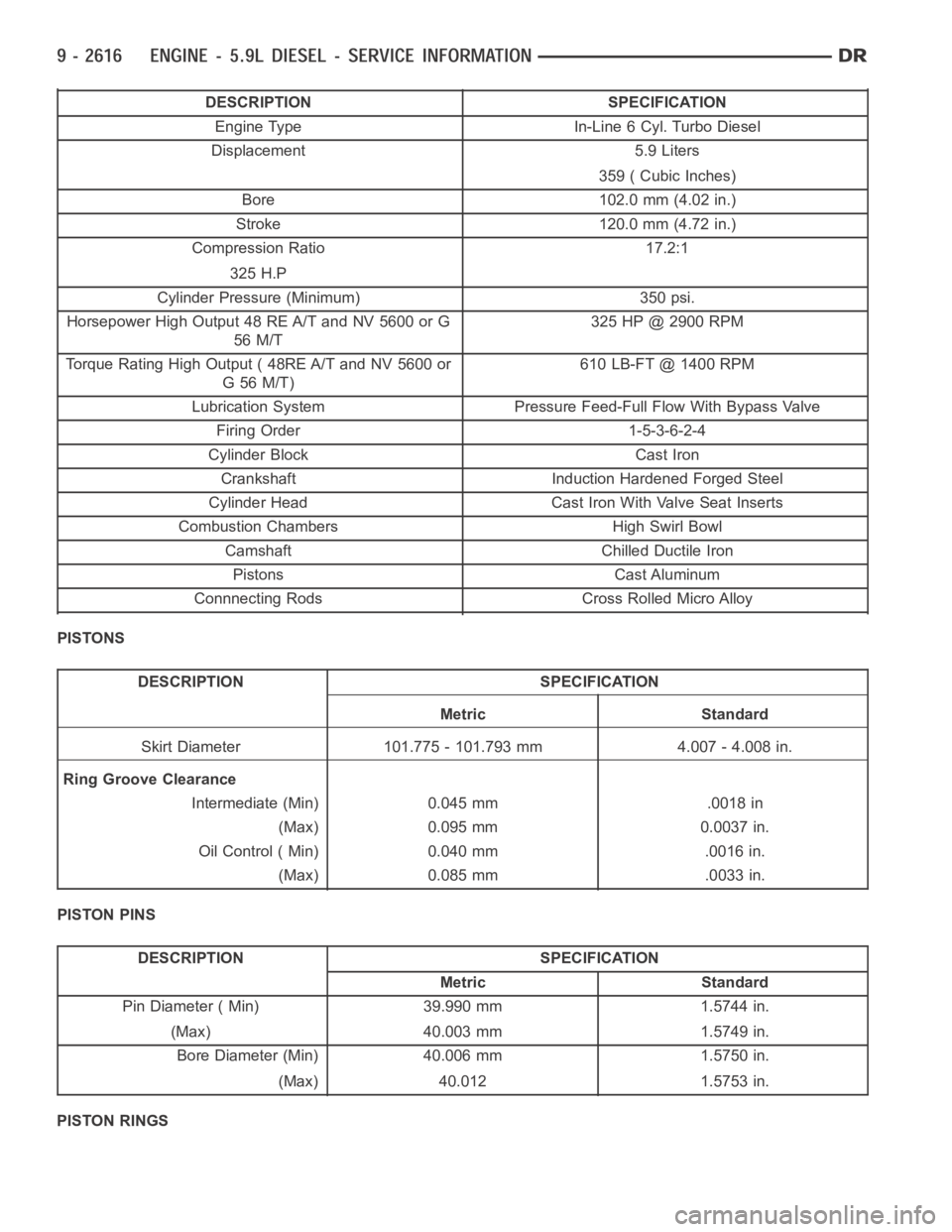
DESCRIPTION SPECIFICATION
Engine Type In-Line 6 Cyl. Turbo Diesel
Displacement 5.9 Liters
359 ( Cubic Inches)
Bore 102.0 mm (4.02 in.)
Stroke 120.0 mm (4.72 in.)
Compression Ratio 17.2:1
325 H.P
Cylinder Pressure (Minimum) 350 psi.
Horsepower High Output 48 RE A/T and NV 5600 or G
56 M/T325 HP @ 2900 RPM
Torque Rating High Output ( 48RE A/T and NV 5600 or
G56M/T)610 LB-FT @ 1400 RPM
Lubrication System Pressure Feed-Full Flow With Bypass Valve
Firing Order 1-5-3-6-2-4
Cylinder Block Cast Iron
Crankshaft Induction Hardened Forged Steel
Cylinder Head Cast Iron With Valve Seat Inserts
Combustion Chambers High Swirl Bowl
Camshaft Chilled Ductile Iron
Pistons Cast Aluminum
Connnecting Rods Cross Rolled Micro Alloy
PISTONS
DESCRIPTION SPECIFICATION
Metric Standard
Skirt Diameter 101.775 - 101.793 mm 4.007 - 4.008 in.
Ring Groove Clearance
Intermediate (Min) 0.045 mm .0018 in
(Max) 0.095 mm 0.0037 in.
Oil Control ( Min) 0.040 mm .0016 in.
(Max) 0.085 mm .0033 in.
PISTON PINS
DESCRIPTION SPECIFICATION
Metric Standard
Pin Diameter ( Min) 39.990 mm 1.5744 in.
(Max) 40.003 mm 1.5749 in.
Bore Diameter (Min) 40.006 mm 1.5750 in.
(Max) 40.012 1.5753 in.
PISTON RINGS
Page 1927 of 5267
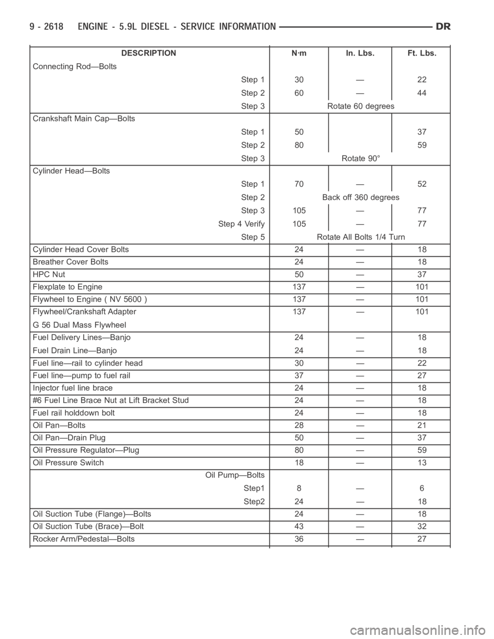
DESCRIPTION Nꞏm In. Lbs. Ft. Lbs.
Connecting Rod—Bolts
Step 1 30 — 22
Step 2 60 — 44
Step 3 Rotate 60 degrees
Crankshaft Main Cap—Bolts
Step 1 50 37
Step 2 80 59
Step 3 Rotate 90°
Cylinder Head—Bolts
Step 1 70 — 52
Step 2 Back off 360 degrees
Step 3 105 — 77
Step 4 Verify 105 — 77
Step 5 Rotate All Bolts 1/4 Turn
Cylinder Head Cover Bolts 24 — 18
Breather Cover Bolts 24 — 18
HPC Nut 50 — 37
Flexplate to Engine 137 — 101
Flywheel to Engine ( NV 5600 ) 137 — 101
Flywheel/Crankshaft Adapter 137 — 101
G 56 Dual Mass Flywheel
Fuel Delivery Lines—Banjo 24 — 18
Fuel Drain Line—Banjo 24 — 18
Fuel line—rail to cylinder head 30 — 22
Fuel line—pump to fuel rail 37 — 27
Injector fuel line brace 24 — 18
#6 Fuel Line Brace Nut at Lift Bracket Stud 24 — 18
Fuel rail holddown bolt 24 — 18
Oil Pan—Bolts 28 — 21
Oil Pan—Drain Plug 50 — 37
Oil Pressure Regulator—Plug 80 — 59
Oil Pressure Switch 18 — 13
Oil Pump—Bolts
Step1 8 — 6
Step2 24 — 18
Oil Suction Tube (Flange)—Bolts 24 — 18
Oil Suction Tube (Brace)—Bolt 43 — 32
Rocker Arm/Pedestal—Bolts 36 — 27
Page 1928 of 5267
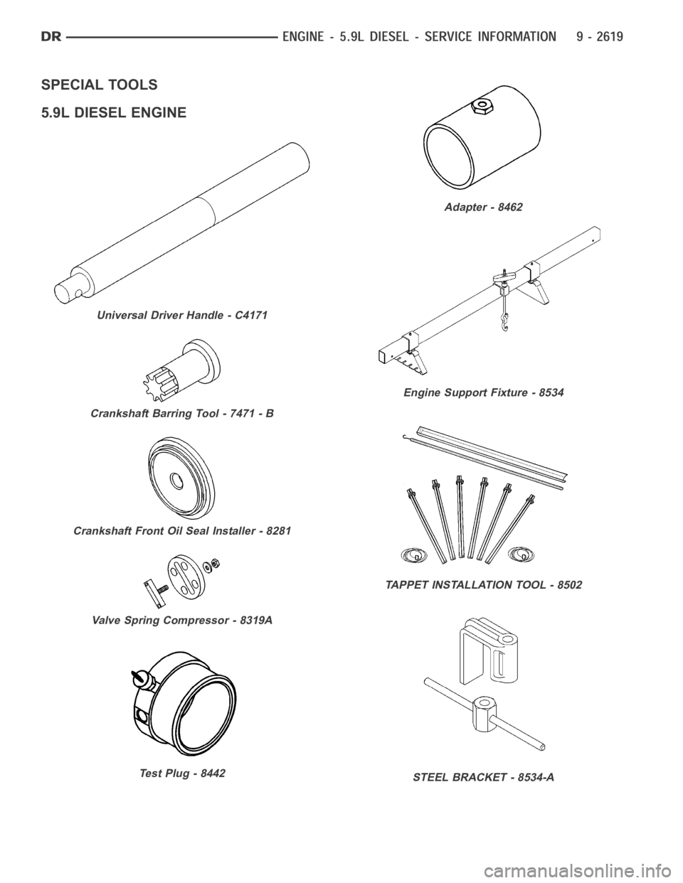
SPECIAL TOOLS
5.9L DIESEL ENGINE
Universal Driver Handle - C4171
Crankshaft Barring Tool - 7471 - B
Crankshaft Front Oil Seal Installer - 8281
Valve Spring Compressor - 8319A
Test Plug - 8442
Adapter - 8462
Engine Support Fixture - 8534
TAPPET INSTALLATION TOOL - 8502
STEEL BRACKET - 8534-A
Page 1952 of 5267
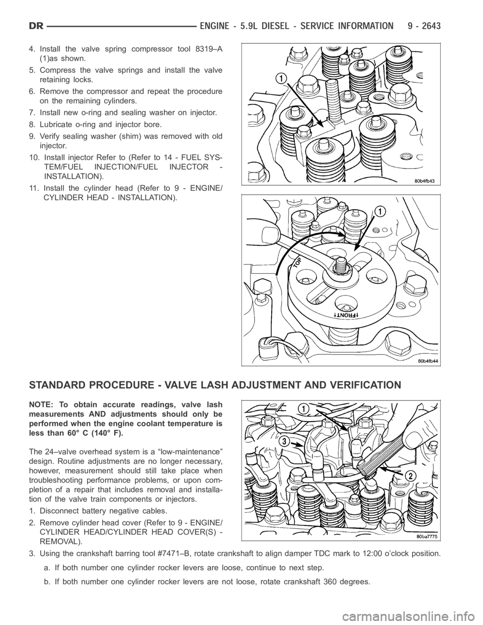
4. Install the valve spring compressor tool 8319–A
(1)as shown.
5. Compress the valve springs and install the valve
retaining locks.
6. Remove the compressor and repeat the procedure
on the remaining cylinders.
7. Install new o-ring and sealing washer on injector.
8. Lubricate o-ring and injector bore.
9. Verify sealing washer (shim) was removed with old
injector.
10. Install injector Refer to (Refer to 14 - FUEL SYS-
TEM/FUEL INJECTION/FUEL INJECTOR -
INSTALLATION).
11. Install the cylinder head (Refer to 9 - ENGINE/
CYLINDER HEAD - INSTALLATION).
STANDARD PROCEDURE - VALVE LASH ADJUSTMENT AND VERIFICATION
NOTE: To obtain accurate readings, valve lash
measurements AND adjustments should only be
performed when the engine coolant temperature is
less than 60° C (140° F).
The 24–valve overhead system is a “low-maintenance”
design. Routine adjustments are no longer necessary,
however, measurement should still take place when
troubleshooting performance problems, or upon com-
pletion of a repair that includes removal and installa-
tion of the valve train components or injectors.
1. Disconnect battery negative cables.
2. Remove cylinder head cover (Refer to 9 - ENGINE/
CYLINDER HEAD/CYLINDER HEAD COVER(S) -
REMOVAL).
3. Using the crankshaft barring tool #7471–B, rotate crankshaft to align damper TDC mark to 12:00 o’clock position.
a. If both number one cylinder rocker levers are loose, continue to next step.
b. If both number one cylinder rocker levers are not loose, rotate crankshaft 360 degrees.
Page 1953 of 5267
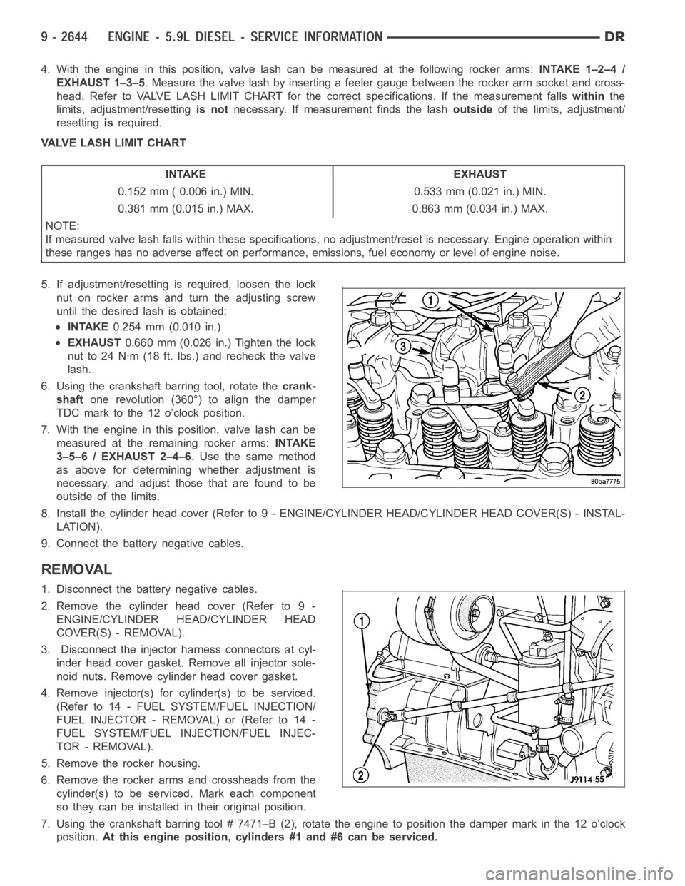
4. With the engine in this position, valve lash can be measured at the following rocker arms:INTAKE 1–2–4 /
EXHAUST 1–3–5. Measure the valve lash by inserting a feeler gauge between the rocker arm socket and cross-
head. Refer to VALVE LASH LIMIT CHART for the correct specifications. If the measurement fallswithinthe
limits, adjustment/resettingis notnecessary. If measurement finds the lashoutsideof the limits, adjustment/
resettingisrequired.
VALVE LASH LIMIT CHART
INTAKE EXHAUST
0.152 mm ( 0.006 in.) MIN. 0.533 mm (0.021 in.) MIN.
0.381 mm (0.015 in.) MAX. 0.863 mm (0.034 in.) MAX.
NOTE:
If measured valve lash falls within these specifications, no adjustment/reset is necessary. Engine operation within
these ranges has no adverse affect on performance, emissions, fuel economy or level of engine noise.
5. If adjustment/resetting is required, loosen the lock
nut on rocker arms and turn the adjusting screw
until the desired lash is obtained:
INTAKE0.254 mm (0.010 in.)
EXHAUST0.660 mm (0.026 in.) Tighten the lock
nut to 24 Nꞏm (18 ft. lbs.) and recheck the valve
lash.
6. Using the crankshaft barring tool, rotate thecrank-
shaftone revolution (360°) to align the damper
TDC mark to the 12 o’clock position.
7. With the engine in this position, valve lash can be
measured at the remaining rocker arms:INTAKE
3–5–6 / EXHAUST 2–4–6. Use the same method
as above for determining whether adjustment is
necessary, and adjust those that are found to be
outside of the limits.
8. Install the cylinder head cover (Refer to 9 - ENGINE/CYLINDER HEAD/CYLINDER HEAD COVER(S) - INSTAL-
LATION).
9. Connect the battery negative cables.
REMOVAL
1. Disconnect the battery negative cables.
2. Remove the cylinder head cover (Refer to 9 -
ENGINE/CYLINDER HEAD/CYLINDER HEAD
COVER(S) - REMOVAL).
3. Disconnect the injector harness connectors at cyl-
inder head cover gasket. Remove all injector sole-
noid nuts. Remove cylinder head cover gasket.
4. Remove injector(s) for cylinder(s) to be serviced.
(Refer to 14 - FUEL SYSTEM/FUEL INJECTION/
FUELINJECTOR-REMOVAL)or(Referto14-
FUEL SYSTEM/FUEL INJECTION/FUEL INJEC-
TOR - REMOVAL).
5. Remove the rocker housing.
6. Remove the rocker arms and crossheads from the
cylinder(s) to be serviced. Mark each component
so they can be installed in their original position.
7. Using the crankshaft barring tool # 7471–B (2), rotate the engine to position the damper mark in the 12 o’clock
position.At this engine position, cylinders #1 and #6 can be serviced.
Page 1954 of 5267
8. Remove the accessory drive belt (Refer to 7 - COOLING/ACCESSORY DRIVE/DRIVE BELTS - REMOVAL).
9. With the damper TDC mark in the 12 o’clock position, add a paint mark anywhere on the gear housing cover
next to the crankshaft damper. Place another mark on the vibration damper in alignment with the mark you just
made on the cover.
10. Divide the crankshaft damper into three equally sized segments as follows:
a. Using a tape measure, measure the circumference of the crankshaft damper and divide the measurement by
three (3).
b. Measure that distance in a counterclockwise direction from the first balancer mark and place another mark
on the balancer.
c. From the second damper mark, again measure in a counterclockwise direction and place a mark on the
damper at the same distance you measured when placing the second damper mark. The damper should
now be marked in three equally spaced locations and the damper TDC mark should be in the 12 o’clock
position.
d. Remove injectors, fuel lines, and high pressure connectors for every cylinder that requires repair.
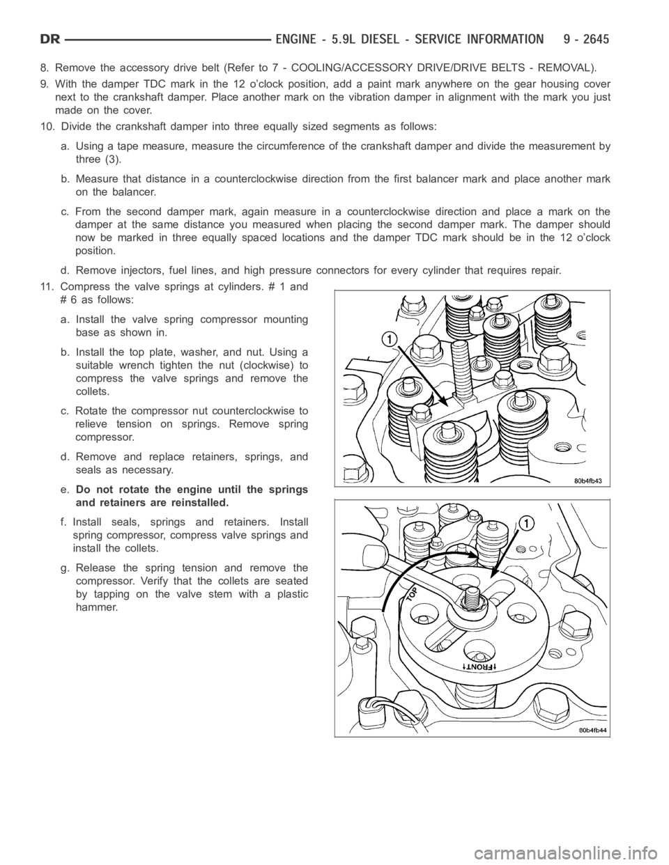
11. Compress the valve springs at cylinders. # 1 and
# 6 as follows:
a. Install the valve spring compressor mounting
base as shown in.
b. Install the top plate, washer, and nut. Using a
suitable wrench tighten the nut (clockwise) to
compress the valve springs and remove the
collets.
c. Rotate the compressor nut counterclockwise to
relieve tension on springs. Remove spring
compressor.
d. Remove and replace retainers, springs, and
seals as necessary.
e.Do not rotate the engine until the springs
and retainers are reinstalled.
f. Install seals, springs and retainers. Install
spring compressor, compress valve springs and
install the collets.
g. Release the spring tension and remove the
compressor. Verify that the collets are seated
by tapping on the valve stem with a plastic
hammer.