Page 1778 of 5267

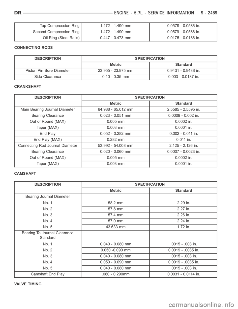
Top Compression Ring 1.472 - 1.490 mm 0.0579 - 0.0586 in.
Second Compression Ring 1.472 - 1.490 mm 0.0579 - 0.0586 in.
Oil Ring (Steel Rails) 0.447 - 0.473 mm 0.0175 - 0.0186 in.
CONNECTING RODS
DESCRIPTION SPECIFICATION
Metric Standard
Piston Pin Bore Diameter 23.955 - 23.975 mm 0.9431 - 0.9438 in.
Side Clearance 0.10 - 0.35 mm 0.003 - 0.0137 in.
CRANKSHAFT
DESCRIPTION SPECIFICATION
Metric Standard
Main Bearing Journal Diameter 64.988 - 65.012 mm 2.5585 - 2.5595 in.
Bearing Clearance 0.023 - 0.051 mm 0.0009 - 0.002 in.
Out of Round (MAX) 0.005 mm 0.0002 in.
Taper (MAX) 0.003 mm 0.0001 in.
End Play 0.052 - 0.282 mm 0.002 - 0.011 in.
End Play (MAX) 0.282 mm 0.011 in.
Connecting Rod Journal Diameter 53.992 - 54.008 mm 2.125 - 2.126 in.
Bearing Clearance 0.020 - 0.060 mm 0.0007 - 0.0023 in.
Out of Round (MAX) 0.005 mm 0.0002 in.
Taper (MAX) 0.003 mm 0.0001 in.
CAMSHAFT
DESCRIPTION SPECIFICATION
Metric Standard
Bearing Journal Diameter
No. 1 58.2 mm 2.29 in.
No. 2 57.8 mm 2.27 in.
No. 3 57.4 mm 2.26 in.
No. 4 57.0 mm 2.24 in.
No. 5 43.633 mm 1.72 in.
Bearing To Journal Clearance
Standard
No. 1 0.040 - 0.080 mm .0015 - .003 in.
No. 2 0.050 -0.090 mm 0.0019 - .0035 in.
No. 3 0.040 - 0.080 mm .0015 - .003 in.
No. 4 0.050 - 0.090 mm 0.0019 - .0035 in.
No. 5 0.040 - 0.080 mm .0015 - .003 in.
Camshaft End Play .080 - 0.290mm 0.0031 - 0.0114 in.
VALVE TIMING
Page 1781 of 5267

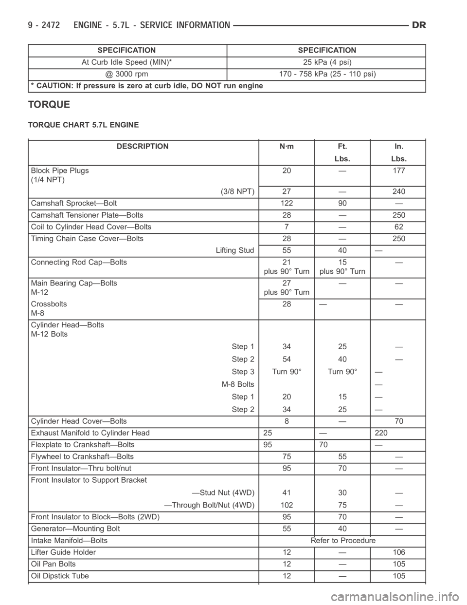
SPECIFICATION SPECIFICATION
At Curb Idle Speed (MIN)* 25 kPa (4 psi)
@ 3000 rpm 170 - 758 kPa (25 - 110 psi)
* CAUTION: If pressure is zero at curb idle, DO NOT run engine
TORQUE
TORQUE CHART 5.7L ENGINE
DESCRIPTION Nꞏm Ft. In.
Lbs. Lbs.
Block Pipe Plugs
(1/4 NPT)20 — 177
(3/8 NPT) 27 — 240
Camshaft Sprocket—Bolt 122 90 —
Camshaft Tensioner Plate—Bolts 28 — 250
Coil to Cylinder Head Cover—Bolts 7 — 62
Timing Chain Case Cover—Bolts 28 — 250
Lifting Stud 55 40 —
Connecting Rod Cap—Bolts 21
plus 90° Turn15
plus 90° Turn—
Main Bearing Cap—Bolts
M-1227
plus 90° Turn——
Crossbolts
M-828 — —
Cylinder Head—Bolts
M-12 Bolts
Step 1 34 25 —
Step 2 54 40 —
Step 3 Turn 90° Turn 90° —
M-8 Bolts —
Step 1 20 15 —
Step 2 34 25 —
Cylinder Head Cover—Bolts 8 — 70
Exhaust Manifold to Cylinder Head 25 — 220
Flexplate to Crankshaft—Bolts 95 70 —
Flywheel to Crankshaft—Bolts 75 55 —
Front Insulator—Thru bolt/nut 95 70 —
Front Insulator to Support Bracket
—Stud Nut (4WD) 41 30 —
—Through Bolt/Nut (4WD) 102 75 —
Front Insulator to Block—Bolts (2WD) 95 70 —
Generator—Mounting Bolt 55 40 —
Intake Manifold—Bolts Refer to Procedure
Lifter Guide Holder 12 — 106
Oil Pan Bolts 12 — 105
Oil Dipstick Tube 12 — 105
Page 1784 of 5267
SPECIAL TOOLS
5.7L ENGINE
BLOC-CHEK KIT C-3685
Bore Size Indicator C-119
Puller 8454
Crankshaft Damper Installer 8512
CRANKSHAFT DAMPER REMOVER INSERT - 8513-A
Dial Indicator C-3339
Handle C-4171
Page 1785 of 5267
Oil Pressure Gauge C-3292
Piston Ring Compressor C-385
Pressure Tester Kit 7700
Rear Crankshaft Seal Installer 8349
Rear Crankshaft Seal Remover 8506
Valve Spring Compressor C-3422-B
Valve Spring Tester C-647
Adapter, Valve Spring Compressor Off-vehicle 8464
Page 1824 of 5267

ENGINE BLOCK
CLEANING
Thoroughly clean the oil pan and engine block gasket surfaces.
Use compressed air to clean out:
The galley at the oil filter adaptor hole.
The front and rear oil galley holes.
The feed holes for the crankshaft main bearings.
Once the block has been completely cleaned, apply Loctite PST pipe sealantwith Teflon 592 to the threads of the
front and rear oil galley plugs. Tighten the 1/4 inch NPT plugs to 20 Nꞏm (177in. lbs.) torque. Tighten the 3/8 inch
NPT plugs to 27 Nꞏm (240 in. lbs.) torque.
INSPECTION
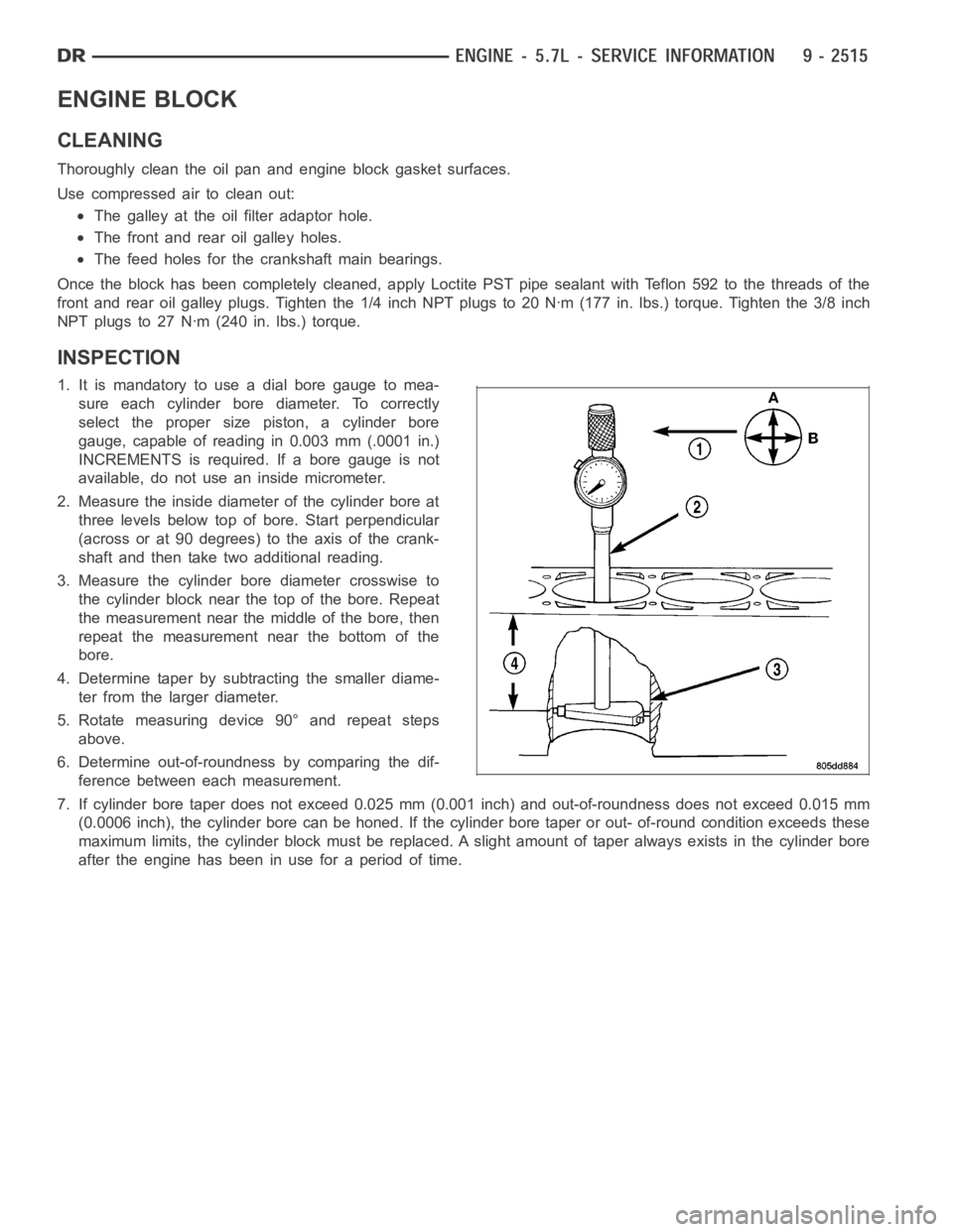
1. It is mandatory to use a dial bore gauge to mea-
sure each cylinder bore diameter. To correctly
select the proper size piston, a cylinder bore
gauge, capable of reading in 0.003 mm (.0001 in.)
INCREMENTS is required. If a bore gauge is not
available, do not use an inside micrometer.
2. Measure the inside diameter of the cylinder bore at
three levels below top of bore. Start perpendicular
(across or at 90 degrees) to the axis of the crank-
shaft and then take two additional reading.
3. Measure the cylinder bore diameter crosswise to
the cylinder block near the top of the bore. Repeat
the measurement near the middle of the bore, then
repeat the measurement near the bottom of the
bore.
4. Determine taper by subtracting the smaller diame-
ter from the larger diameter.
5. Rotate measuring device 90° and repeat steps
above.
6. Determine out-of-roundness by comparing the dif-
ference between each measurement.
7. If cylinder bore taper does not exceed 0.025 mm (0.001 inch) and out-of-roundness does not exceed 0.015 mm
(0.0006 inch), the cylinder bore can be honed. If the cylinder bore taper orout- of-round condition exceeds these
maximum limits, the cylinder block must be replaced. A slight amount of taper always exists in the cylinder bore
after the engine has been in use for a period of time.
Page 1836 of 5267
CRANKSHAFT
REMOVAL
1. Remove the vibration damper (1) (Refer to 9 -
ENGINE/ENGINE BLOCK/VIBRATION DAMPER -
REMOVAL).
2. Remove the rear oil seal retainer (Refer to 9 -
ENGINE/ENGINE BLOCK/CRANKSHAFT REAR
OIL SEAL RETAINE - REMOVAL).
3. Remove the oil pan (Refer to 9 - ENGINE/LUBRI-
CATION/OIL PAN - REMOVAL).
4. Remove the oil pump pickup.
5. Remove the windage tray/oil pan gasket.
Page 1839 of 5267
11. Remove main bearing caps (1) and bearings one
at a time.
12. Remove the thrust washers.
13. Remove the crankshaft out of the block.
Page 1840 of 5267
INSTALLATION
1. Select the proper main bearings (Refer to 9 -
ENGINE/ENGINE BLOCK/CRANKSHAFT MAIN
BEARINGS - STANDARD PROCEDURE).
2. Install main bearings in block and caps, and lubri-
cate bearings.
3. Position the crankshaft into the cylinder block.
4. Install the thrust washers (1).