2006 DODGE RAM SRT-10 Crankshaft
[x] Cancel search: CrankshaftPage 2030 of 5267
3. Using a black light, inspect the entire engine for fluorescent dye, particularly at the suspected area of oil leak. If
the oil leak is found and identified, repair as necessary.
4. If dye is not observed, drive the vehicle at various speeds for approximately 24 km (15 miles), and repeat inspec-
tion.
5.If the oil leak source is not positively identified at this time, proceed with the air leak detection test method
as follows:
1. Disconnect the PCV hoses at the cylinder head covers and plug or cap the outlet on the covers.
2. Attach an air hose with pressure gauge and regulator to the dipstick tube.
CAUTION: Do not subject the engine assembly to more than 20.6 kpa (3 PSI) of test pressure.
3. Gradually apply air pressure from 6.89 kPa (1 psi) to 17.23 kPa (2.5 psi) maximum while applying soapy water
at the suspected source. Adjust the regulator to the suitable test pressure that provides the best bubbles which
will pinpoint the leak source. If the oil leak is detected and identified, repair per service manual procedures.
4. If the leakage occurs at the crankshaft rear oil seal area, refer to the section, Inspection for Rear Seal Area
Leak.
6. If no leaks are detected, turn off the air supply. Remove the air hose, allplugs, and caps. Connect the PCV
hoses. Proceed to next step.
7. Clean the oil off the suspect oil leak area using a suitable solvent. Drive the vehicle at various speeds approx-
imately 24 km (15 miles). Inspect the engine for signs of an oil leak by usinga black light.
NOTE: If oil leakage is observed at the dipstick tube to oil pan location; remove the tube, clean and reseal
using Mopar
Stud & Bearing Mount (press fit tube applications only), and for O-ring style tubes, remove
tube and replace the O-ring seal.
INSPECTION FOR REAR SEAL AREA LEAKS
Since it is sometimes difficult to determine the source of an oil leak in therear seal area of the engine, a more
involved inspection is necessary. The following steps should be followedto help pinpoint the source of the leak.
If the leakage occurs at the crankshaft rear oil seal area:
1. Disconnect the battery.
2. Raise the vehicle.
3. Remove clutch housing inspection cover and inspect rear of block for evidence of oil. Use a black light to check
for the oil leak. If a leak is present in this area, remove transmission for further inspection.
a. Circular spray pattern generally indicates seal leakage or crankshaftdamage.
b. Where leakage tends to run straight down, possible causes are a porous block, oil gallery cup plug or rear
crankshaft seal retainer gasket leak. See proper repair procedures for these items.
4. If no leaks are detected, pressurize the crankcase as previously described.
CAUTION: Do not exceed 20.6 kPa (3 psi).
5. If the leak is not detected, very slowly turn the crankshaft and watch forleakage. If a leak is detected between
the crankshaft and seal while slowly turning the crankshaft, it is possible the crankshaft seal surface is damaged.
The seal area on the crankshaft could have minor nicks or scratches that canbe polished out with emery cloth.
CAUTION: Use extreme caution when crankshaft polishing is necessary to remove minor nicks and
scratches. The crankshaft seal flange is especially machined to complement the function of the rear oil seal.
6. For bubbles that remain steady with shaft rotation, no further inspection can be done until disassembled.
7. After the oil leak root cause and appropriate corrective action have been identified, replace component(s) as
necessary.
Page 2032 of 5267
material also will prevent corrosion. MoparGasket Sealant is available in a 13 oz. aerosol can or 4 oz./16 oz. can
w/applicator.
FORM-IN-PLACE GASKET AND SEALER APPLICATION
MoparGasket Maker material should be applied sparingly 1 mm (0.040 in.) diameter or less of sealant to one
gasket surface. Be certain the material surrounds each mounting hole. Excess material can easily be wiped off.
Components should be torqued in place within 15 minutes. The use of a locating dowel is recommended during
assembly to prevent smearing material off the location.
Mopar
Engine RTV GEN II or ATF RTV gasket material should be applied in a continuous bead approximately 3
mm (0.120 in.) in diameter. All mounting holes must be circled. For corner sealing,a3.17mmor6.35mm(1/8in.
or 1/4 in.) drop is placed in the center of the gasket contact area. Uncured sealant may be removed with a shop
towel. Components should be torqued in place while the sealant is still wettothetouch(within10minutes).The
usage of a locating dowel is recommended during assembly to prevent smearing material off the location.
Mopar
Gasket Sealant in an aerosol can should be applied using a thin, even coat sprayed completely over both
surfaces to be joined, and both sides of a gasket. Then proceed with assembly. Material in a can w/applicator can
be brushed on evenly over the sealing surfaces. Material in an aerosol can shouldbeusedonengineswithmulti-
layer steel gaskets.
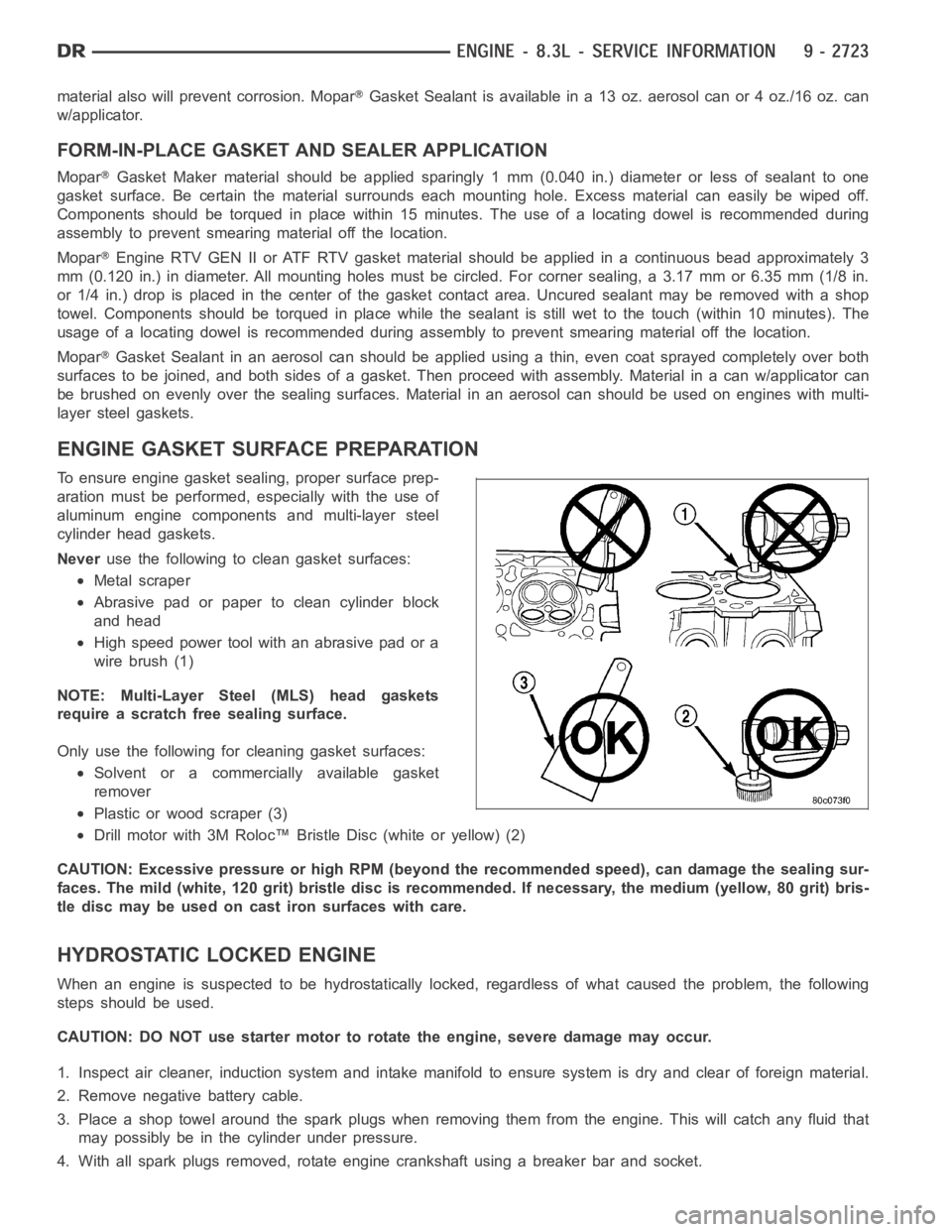
ENGINE GASKET SURFACE PREPARATION
To ensure engine gasket sealing, proper surface prep-
aration must be performed, especially with the use of
aluminum engine components and multi-layer steel
cylinder head gaskets.
Neveruse the following to clean gasket surfaces:
Metal scraper
Abrasive pad or paper to clean cylinder block
and head
High speed power tool with an abrasive pad or a
wire brush (1)
NOTE: Multi-Layer Steel (MLS) head gaskets
require a scratch free sealing surface.
Only use the following for cleaning gasket surfaces:
Solvent or a commercially available gasket
remover
Plastic or wood scraper (3)
Drill motor with 3M Roloc™ Bristle Disc (white or yellow) (2)
CAUTION: Excessive pressure or high RPM (beyond the recommended speed), can damage the sealing sur-
faces. The mild (white, 120 grit) bristle disc is recommended. If necessary, the medium (yellow, 80 grit) bris-
tle disc may be used on cast iron surfaces with care.
HYDROSTATIC LOCKED ENGINE
When an engine is suspected to be hydrostatically locked, regardless of what caused the problem, the following
steps should be used.
CAUTION: DO NOT use starter motor to rotate the engine, severe damage may occur.
1. Inspect air cleaner, induction system and intake manifold to ensure system is dry and clear of foreign material.
2. Remove negative battery cable.
3. Place a shop towel around the spark plugs when removing them from the engine. This will catch any fluid that
may possibly be in the cylinder under pressure.
4. With all spark plugs removed, rotate engine crankshaft using a breaker bar and socket.
Page 2040 of 5267
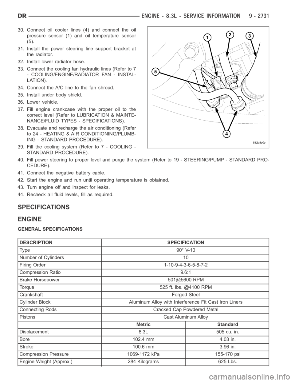
30. Connect oil cooler lines (4) and connect the oil
pressure sensor (1) and oil temperature sensor
(5).
31. Install the power steering line support bracket at
the radiator.
32. Install lower radiator hose.
33. Connect the cooling fan hydraulic lines (Refer to 7
- COOLING/ENGINE/RADIATOR FAN - INSTAL-
LATION).
34. Connect the A/C line to the fan shroud.
35. Install under body shield.
36. Lower vehicle.
37. Fill engine crankcase with the proper oil to the
correct level (Refer to LUBRICATION & MAINTE-
NANCE/FLUID TYPES - SPECIFICATIONS).
38. Evacuate and recharge the air conditioning (Refer
to 24 - HEATING & AIR CONDITIONING/PLUMB-
ING - STANDARD PROCEDURE).
39. Fill the cooling system (Refer to 7 - COOLING -
STANDARD PROCEDURE).
40. Fill power steering to proper leveland purge the system (Refer to 19 - STEERING/PUMP - STANDARD PRO-
CEDURE).
41. Connect the negative battery cable.
42. Start the engine and run until operating temperature is obtained.
43. Turn engine off and inspect for leaks.
44. Recheck all fluid levels, fill as required.
SPECIFICATIONS
ENGINE
GENERAL SPECIFICATIONS
DESCRIPTION SPECIFICATION
Ty pe 9 0° V-1 0
Number of Cylinders 10
Firing Order 1-10-9-4-3-6-5-8-7-2
Compression Ratio 9.6:1
Brake Horsepower 501@5600 RPM
Torque 525 ft. lbs. @4100 RPM
Crankshaft Forged Steel
Cylinder Block Aluminum Alloy with Interference Fit Cast Iron Liners
Connecting Rods Cracked Cap Powdered Metal
Pistons Cast Aluminum Alloy
Metric Standard
Displacement 8.3L 505 cu. in.
Bore 102.4 mm 4.03 in.
Stroke 100.6 mm 3.96 in.
Compression Pressure 1069-1172 kPa 155-170 psi
Engine Weight (Approx.) 284 Kilograms 625 Lbs.
Page 2041 of 5267
CYLINDER BLOCK
DESCRIPTIONSPECIFICATION
Metric Standard
Cylinder Bore Diameter 102.356-102.368 mm 4.02975-4.03025 in.
Out of Round (Max.) 0.051 mm 0.002 in.
Taper (Max.) 0.038 mm 0.0015 in.
Tappet Bore Diameter 22.974-22.992 mm 0.9045-0.9052 in.
Block Length 693.7 mm 27.310 in.
Block Height 240.8 mm 9.48 in.
CRANKSHAFT
DESCRIPTIONSPECIFICATION
Metric Standard
Connecting Rod Journal Diameter 53.990-54.008 mm 2.1256-2.1263 in.
Out-of-Round (Max.) 0.013 mm 0.0005 in.
Taper (Max.) 0.013 mm 0.0005 in
End Play 0.051-0.178 mm 0.002-0.007 in.
Desired 0.13 mm 0.005 in.
Wear Limit 0.254 mm 0.010 in.
Main Bearing Clearance 1-6 0.025-0.051 mm 0.001-0.002 in.
Wear Limit 0.076 mm 0.003 in.
MAIN BEARING JOURNALS
DESCRIPTIONSPECIFICATION
Metric Standard
Diameter-High 76.233-76.246 mm 3.0013-3.0018 in.
Diameter-Low 76.220-76.223 mm 3.0008-3.0013 in.
Out of Round (Max.) 0.013 mm 0.0005 in
CONNECTING RODS
DESCRIPTIONSPECIFICATION
Metric Standard
Bearing Clearance 0.005-0.074 mm. 0.0002-0.0029 in.
Desired 0.0381mm 0.0015in.
Wear Limit 0.0889 mm 0.0035 in.
Piston Pin Boar Diameter 23.940-23.978 mm 0.9425-0.9440 in.
Side Clearance (Two Rods) 0.25-0.46 mm 0.010-0.018 in.
Wear Limit 0.51 mm 0.020 in.
Total Weight (Less Bearing) 598.4 grams 21.11 oz.
PISTONS
Page 2045 of 5267
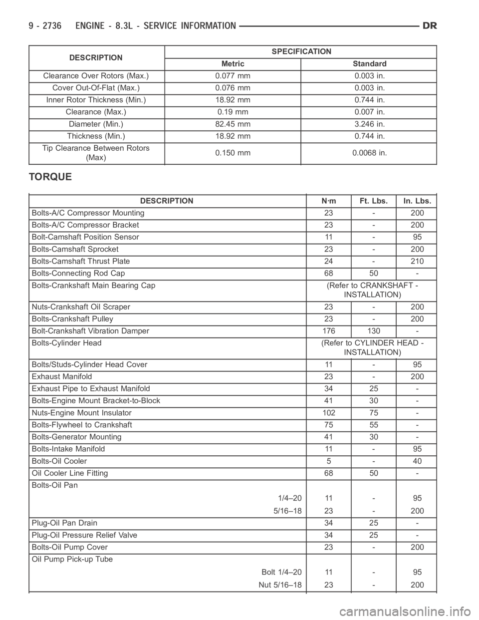
DESCRIPTIONSPECIFICATION
Metric Standard
Clearance Over Rotors (Max.) 0.077 mm 0.003 in.
Cover Out-Of-Flat (Max.) 0.076 mm 0.003 in.
Inner Rotor Thickness (Min.) 18.92 mm 0.744 in.
Clearance (Max.) 0.19 mm 0.007 in.
Diameter (Min.) 82.45 mm 3.246 in.
Thickness (Min.) 18.92 mm 0.744 in.
Tip Clearance Between Rotors
(Max)0.150 mm 0.0068 in.
TORQUE
DESCRIPTION Nꞏm Ft. Lbs. In. Lbs.
Bolts-A/C Compressor Mounting 23 - 200
Bolts-A/C Compressor Bracket 23 - 200
Bolt-Camshaft Position Sensor 11 - 95
Bolts-Camshaft Sprocket 23 - 200
Bolts-Camshaft Thrust Plate 24 - 210
Bolts-Connecting Rod Cap 68 50 -
Bolts-Crankshaft Main Bearing Cap (Refer to CRANKSHAFT -
INSTALLATION)
Nuts-Crankshaft Oil Scraper 23 - 200
Bolts-Crankshaft Pulley 23 - 200
Bolt-Crankshaft Vibration Damper 176 130 -
Bolts-Cylinder Head (Refer to CYLINDER HEAD -
INSTALLATION)
Bolts/Studs-Cylinder Head Cover 11 - 95
Exhaust Manifold 23 - 200
Exhaust Pipe to Exhaust Manifold 34 25 -
Bolts-Engine Mount Bracket-to-Block 41 30 -
Nuts-Engine Mount Insulator 102 75 -
Bolts-Flywheel to Crankshaft 75 55 -
Bolts-Generator Mounting 41 30 -
Bolts-Intake Manifold 11 - 95
Bolts-Oil Cooler 5 - 40
Oil Cooler Line Fitting 68 50 -
Bolts-Oil Pan
1/4–20 11 - 95
5/16–18 23 - 200
Plug-Oil Pan Drain 34 25 -
Plug-Oil Pressure Relief Valve 34 25 -
Bolts-Oil Pump Cover 23 - 200
Oil Pump Pick-up Tube
Bolt 1/4–20 11 - 95
Nut 5/16–18 23 - 200
Page 2046 of 5267
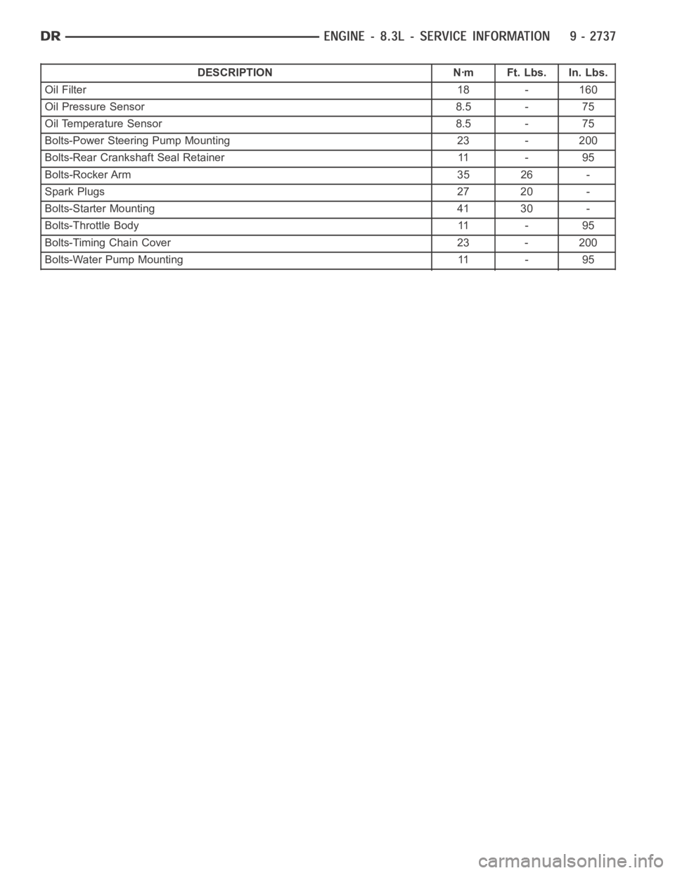
DESCRIPTION Nꞏm Ft. Lbs. In. Lbs.
Oil Filter18 - 160
Oil Pressure Sensor 8.5 - 75
Oil Temperature Sensor 8.5 - 75
Bolts-Power Steering Pump Mounting 23 - 200
Bolts-Rear Crankshaft Seal Retainer 11 - 95
Bolts-Rocker Arm 35 26 -
Spark Plugs27 20 -
Bolts-Starter Mounting 41 30 -
Bolts-Throttle Body 11 - 95
Bolts-Timing Chain Cover 23 - 200
Bolts-Water Pump Mounting 11 - 95
Page 2047 of 5267
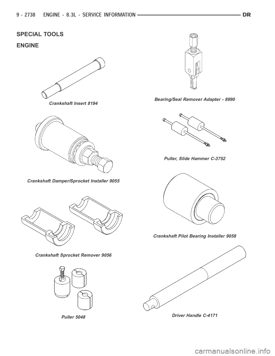
SPECIAL TOOLS
ENGINE
Crankshaft Insert 8194
Crankshaft Damper/Sprocket Installer 9055
Crankshaft Sprocket Remover 9056
Puller 5048
Bearing/Seal Remover Adapter - 8990
Puller, Slide Hammer C-3752
Crankshaft Pilot Bearing Installer 9058
Driver Handle C-4171
Page 2048 of 5267
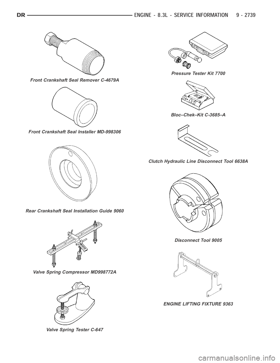
Front Crankshaft Seal Remover C-4679A
Front Crankshaft Seal Installer MD-998306
Rear Crankshaft Seal Installation Guide 9060
Valve Spring Compressor MD998772A
Valve Spring Tester C-647
Pressure Tester Kit 7700
Bloc–Chek–Kit C-3685–A
Clutch Hydraulic Line Disconnect Tool 6638A
Disconnect Tool 9005
ENGINE LIFTING FIXTURE 9363