2006 DODGE RAM SRT-10 Crankshaft
[x] Cancel search: CrankshaftPage 2132 of 5267
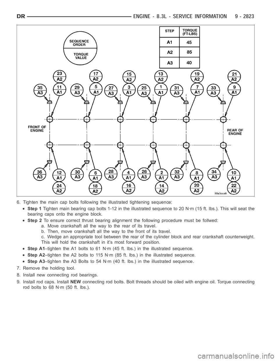
6. Tighten the main cap bolts following the illustrated tightening sequence:
Step 1Tighten main bearing cap bolts 1-12 inthe illustrated sequence to 20 Nꞏm (15 ft. lbs.). This will seat the
bearing caps onto the engine block.
Step 2To ensure correct thrust bearing alignment the following procedure must be follwed:
a. Move crankshaft all the way to the rear of its travel.
b. Then, move crankshaft all the way to the front of its travel.
c. Wedge an appropriate tool between the rear of the cylinder block and rearcrankshaft counterweight.
This will hold the crankshaft in it’s most forward position.
Step A1–tighten the A1 bolts to 61 Nꞏm (45 ft. lbs.) in the illustrated sequence.
Step A2–tighten the A2 bolts to 115 Nꞏm (85 ft. lbs.) in the illustrated sequence.
Step A3–tighten the A3 Bolts to 54 Nꞏm (40 ft. lbs.) in the illustrated sequence.
7. Remove the holding tool.
8. Install new connecting rod bearings.
9. Install rod caps. InstallNEWconnecting rod bolts. Bolt threads should be oiled with engine oil. Torqueconnecting
rod bolts to 68 Nꞏm (50 ft. lbs.).
Page 2133 of 5267
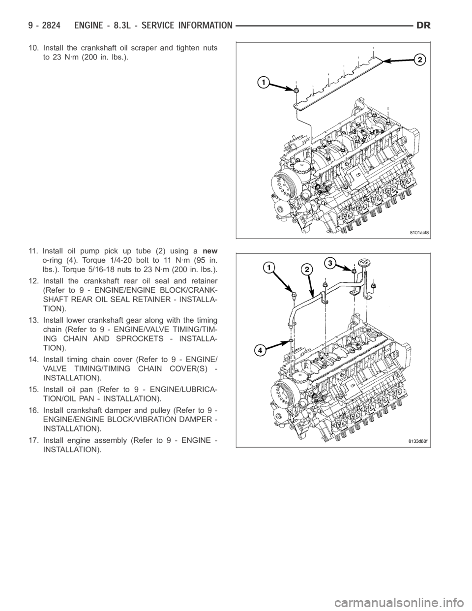
10. Install the crankshaft oil scraper and tighten nuts
to 23 Nꞏm (200 in. lbs.).
11.Installoilpumppickuptube(2)usinganew
o-ring (4). Torque 1/4-20 bolt to 11 Nꞏm (95 in.
lbs.). Torque 5/16-18 nuts to 23 Nꞏm (200 in. lbs.).
12. Install the crankshaft rear oil seal and retainer
(Refer to 9 - ENGINE/ENGINE BLOCK/CRANK-
SHAFT REAR OIL SEAL RETAINER - INSTALLA-
TION).
13. Install lower crankshaft gear along with the timing
chain (Refer to 9 - ENGINE/VALVE TIMING/TIM-
ING CHAIN AND SPROCKETS - INSTALLA-
TION).
14. Install timing chain cover (Refer to 9 - ENGINE/
VALVE TIMING/TIMING CHAIN COVER(S) -
INSTALLATION).
15. Install oil pan (Refer to 9 - ENGINE/LUBRICA-
TION/OIL PAN - INSTALLATION).
16. Install crankshaft damper and pulley (Refer to 9 -
ENGINE/ENGINE BLOCK/VIBRATION DAMPER -
INSTALLATION).
17. Install engine assembly (Refer to 9 - ENGINE -
INSTALLATION).
Page 2134 of 5267
BEARING-CRANKSHAFT PILOT
REMOVAL
1. Remove transmission (Refer to 21 - TRANSMIS-
SION/TRANSAXLE/MANUAL - REMOVAL).
2. Remove clutch and flywheel (Refer to 6 - CLUTCH/
CLUTCH DISC - REMOVAL).
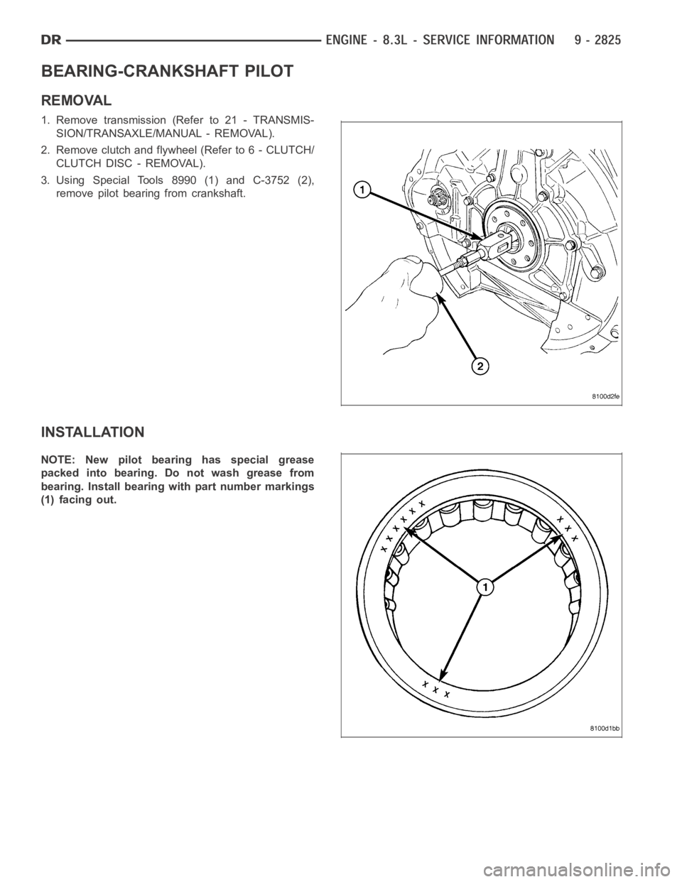
3. Using Special Tools 8990 (1) and C-3752 (2),
remove pilot bearing from crankshaft.
INSTALLATION
NOTE: New pilot bearing has special grease
packed into bearing. Do not wash grease from
bearing. Install bearing with part number markings
(1) facing out.
Page 2242 of 5267

8. Connect other end of jumper wire to positive side of battery.
9. Connect one end of a second jumper wire to remaining injector terminal.
CAUTION: Powering an injector for more than a few seconds will permanentlydamage the injector.
10. Momentarily touch other end of jumper wire to negative terminal of battery for no more than a few seconds.
11. Place a rag or towel below fuel line quick-connect fitting at fuel rail.
12. Disconnect quick-connect fitting at fuel rail. Refer to Quick-Connect Fittings.
13. Return fuel pump relay to PDC.
14. One or more Diagnostic Trouble Codes (DTC’s) may have been stored in PCMmemory due to fuel pump relay
removal. The DRB
scantoolmustbeusedtoeraseaDTC.
STANDARD PROCEDURE - DRAINING FUEL TANK - EXCEPT DIESEL
WARNING: The fuel system may be under constant fuel pressure even with the engine off. This pressure
must be released before servicing fuel tank.
Two different procedures may be used to drain fuel tank: through the fuel fill fitting on tank, or using a diagnostic
scan tool to activate the fuel pump relay. Due to a one-way check valve installed into the fuel fill opening fitting at
the tank, the tank cannot be drained conventionally at the fill cap.
The quickest draining procedure involves removing the rubber fuel fill hose at the fuel tank.
As an alternative procedure, the electric fuel pump may be activated allowingtanktobedrainedatfuelrailcon-
nection. Refer to diagnostic scan tool for fuel pump activation procedures. Before disconnecting fuel line at fuel rail,
release fuel pressure. Refer to the Fuel System Pressure Release Procedure for procedures. Attach end of special
test hose tool number 6631 or 6539 at fuel rail disconnection (tool number 6631isusedon5/16”fuellineswhile
tool number 6539 is used on 3/8” fuel lines). Position opposite end of this hose tool to an approved gasoline drain-
ing station. Activate fuel pump and drain tank until empty.
If electric fuel pump is not operating, fuel must be drained through fuel fill fitting at tank. Refer to following proce-
dures.
1. Release fuel system pressure.
2. Raise vehicle.
3. Thoroughly clean area around fuel fill fitting and rubber fuel fill hoseat tank.
4. If vehicle is equipped with 4 doors and a 6 foot (short) box, remove left-rear tire/wheel.
5. Loosen clamp and disconnect rubber fuel fill hose at tank fitting. Usingan approved gas holding tank, drain fuel
tank through this fitting.
SPECIFICATIONS
FUEL SYSTEM PRESSURE
58 psi +/- 2 psi
TORQUE - EXCEPT DIESEL
DESCRIPTION N-m Ft. Lbs. In. Lbs.
Accelerator Pedal Bracket
Mounting12 - 105
Accelerator Pedal Position
Sensor Bracket-to-Battery
Tray Bolts3-30
Crankshaft Position
Sensor - 3.7L28 21 -
Crankshaft Position
Sensor - 4.7L28 21 -
Page 2243 of 5267
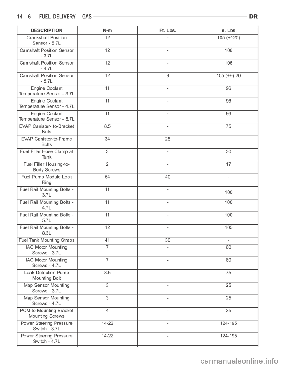
DESCRIPTION N-m Ft. Lbs. In. Lbs.
Crankshaft Position
Sensor - 5.7L12 - 105 (+/-20)
Camshaft Position Sensor
-3.7L12 - 106
Camshaft Position Sensor
-4.7L12 - 106
Camshaft Position Sensor
-5.7L12 9 105 (+/-) 20
Engine Coolant
Temperature Sensor - 3.7L11 - 9 6
Engine Coolant
Temperature Sensor - 4.7L11 - 9 6
Engine Coolant
Temperature Sensor - 5.7L11 - 9 6
EVAP Canister- to-Bracket
Nuts8.5 - 75
EVAP Canister-to-Frame
Bolts34 25
Fuel Filler Hose Clamp at
Tank3-30
Fuel Filler Housing-to-
Body Screws2-17
Fuel Pump Module Lock
Ring54 40 -
Fuel Rail Mounting Bolts -
3.7L11 -
100
Fuel Rail Mounting Bolts -
4.7L11 - 1 0 0
Fuel Rail Mounting Bolts -
5.7L11 - 1 0 0
Fuel Rail Mounting Bolts -
8.3L12 - 105
Fuel Tank Mounting Straps 41 30 -
IAC Motor Mounting
Screws - 3.7L7-60
IAC Motor Mounting
Screws - 4.7L7-60
Leak Detection Pump
Mounting Bolt8.5 - 75
Map Sensor Mounting
Screws - 3.7L3-25
Map Sensor Mounting
Screws - 4.7L3-25
PCM-to-Mounting Bracket
Mounting Screws4-35
Power Steering Pressure
Switch - 3.7L14-22 - 124-195
Power Steering Pressure
Switch - 4.7L14-22 - 124-195
Page 2281 of 5267
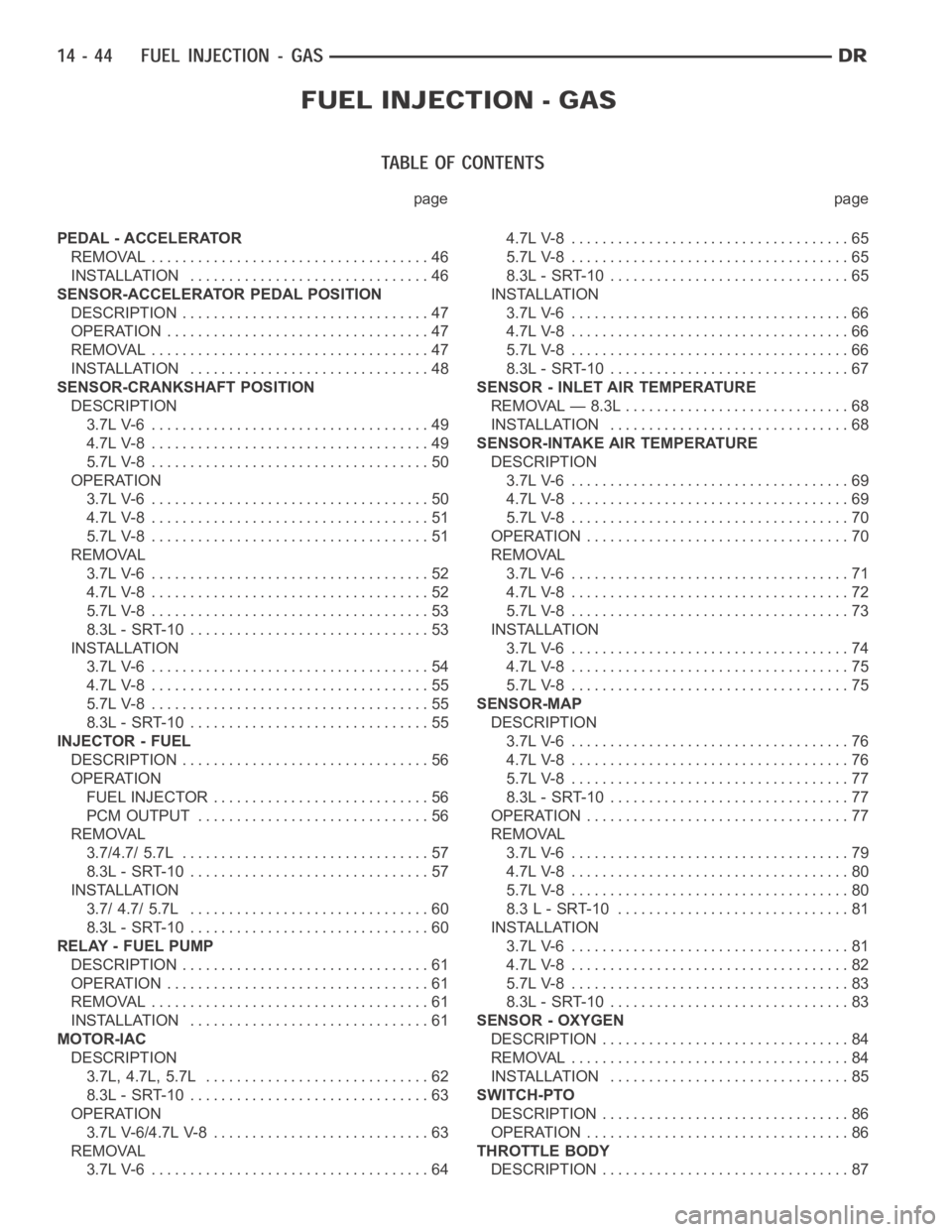
page page
PEDAL - ACCELERATOR
REMOVAL .................................... 46
INSTALLATION ............................... 46
SENSOR-ACCELERATOR PEDAL POSITION
DESCRIPTION ................................ 47
OPERATION .................................. 47
REMOVAL .................................... 47
INSTALLATION ............................... 48
SENSOR-CRANKSHAFT POSITION
DESCRIPTION
3.7L V-6 .................................... 49
4.7L V-8 .................................... 49
5.7L V-8 .................................... 50
OPERATION
3.7L V-6 .................................... 50
4.7L V-8 .................................... 51
5.7L V-8 .................................... 51
REMOVAL
3.7L V-6 .................................... 52
4.7L V-8 .................................... 52
5.7L V-8 .................................... 53
8.3L - SRT-10 ............................... 53
INSTALLATION
3.7L V-6 .................................... 54
4.7L V-8 .................................... 55
5.7L V-8 .................................... 55
8.3L - SRT-10 ............................... 55
INJECTOR - FUEL
DESCRIPTION ................................ 56
OPERATION
FUEL INJECTOR ............................ 56
PCM OUTPUT .............................. 56
REMOVAL
3.7/4.7/ 5.7L ................................ 57
8.3L - SRT-10 ............................... 57
INSTALLATION
3.7/ 4.7/ 5.7L ............................... 60
8.3L - SRT-10 ............................... 60
RELAY - FUEL PUMP
DESCRIPTION ................................ 61
OPERATION .................................. 61
REMOVAL .................................... 61
INSTALLATION ............................... 61
MOTOR-IAC
DESCRIPTION
3.7L, 4.7L, 5.7L ............................. 62
8.3L - SRT-10 ............................... 63
OPERATION
3.7L V-6/4.7L V-8 ............................ 63
REMOVAL
3.7L V-6 .................................... 644.7L V-8 .................................... 65
5.7L V-8 .................................... 65
8.3L - SRT-10 ............................... 65
INSTALLATION
3.7L V-6 .................................... 66
4.7L V-8 .................................... 66
5.7L V-8 .................................... 66
8.3L - SRT-10 ............................... 67
SENSOR - INLET AIR TEMPERATURE
REMOVAL — 8.3L ............................. 68
INSTALLATION ............................... 68
SENSOR-INTAKE AIR TEMPERATURE
DESCRIPTION
3.7L V-6 .................................... 69
4.7L V-8 .................................... 69
5.7L V-8 .................................... 70
OPERATION .................................. 70
REMOVAL
3.7L V-6 .................................... 71
4.7L V-8 .................................... 72
5.7L V-8 .................................... 73
INSTALLATION
3.7L V-6 .................................... 74
4.7L V-8 .................................... 75
5.7L V-8 .................................... 75
SENSOR-MAP
DESCRIPTION
3.7L V-6 .................................... 76
4.7L V-8 .................................... 76
5.7L V-8 .................................... 77
8.3L - SRT-10 ............................... 77
OPERATION .................................. 77
REMOVAL
3.7L V-6 .................................... 79
4.7L V-8 .................................... 80
5.7L V-8 .................................... 80
8.3 L - SRT-10 .............................. 81
INSTALLATION
3.7L V-6 .................................... 81
4.7L V-8 .................................... 82
5.7L V-8 .................................... 83
8.3L - SRT-10 ............................... 83
SENSOR - OXYGEN
DESCRIPTION ................................ 84
REMOVAL .................................... 84
INSTALLATION ............................... 85
SWITCH-PTO
DESCRIPTION ................................ 86
OPERATION .................................. 86
THROTTLE BODY
DESCRIPTION ................................ 87
Page 2286 of 5267
SENSOR-CRANKSHAFT POSITION
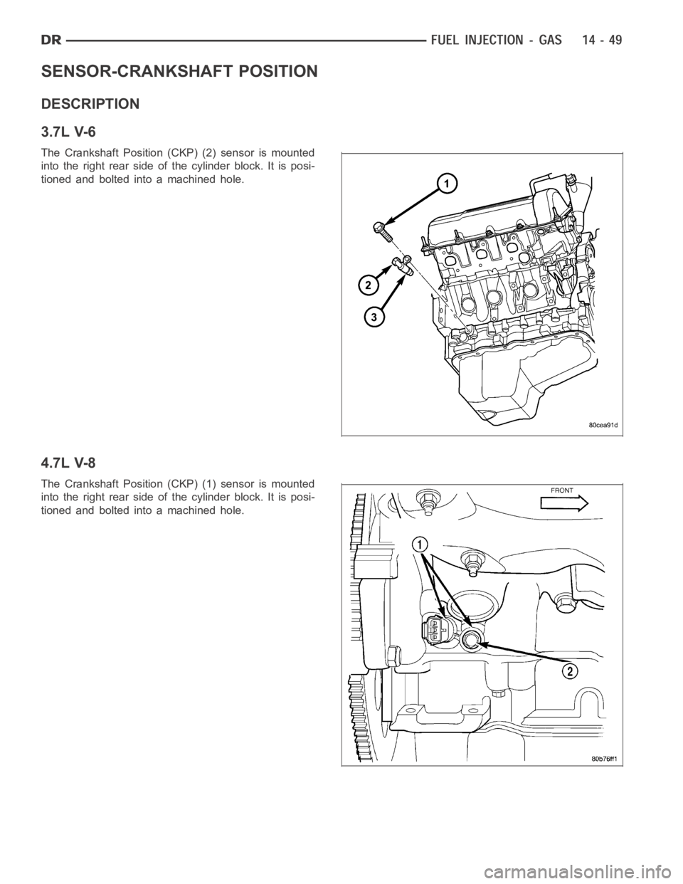
DESCRIPTION
3.7L V-6
The Crankshaft Position (CKP) (2) sensor is mounted
into the right rear side of the cylinder block. It is posi-
tioned and bolted into a machined hole.
4.7L V-8
The Crankshaft Position (CKP) (1) sensor is mounted
into the right rear side of the cylinder block. It is posi-
tioned and bolted into a machined hole.
Page 2287 of 5267
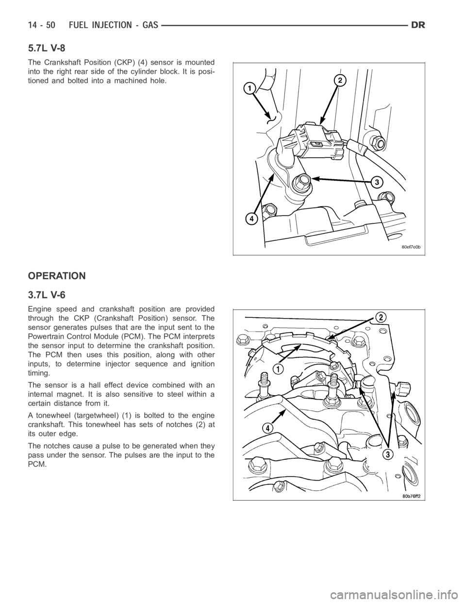
5.7L V-8
The Crankshaft Position (CKP) (4) sensor is mounted
into the right rear side of the cylinder block. It is posi-
tioned and bolted into a machined hole.
OPERATION
3.7L V-6
Engine speed and crankshaft position are provided
through the CKP (Crankshaft Position) sensor. The
sensor generates pulses that are the input sent to the
Powertrain Control Module (PCM). The PCM interprets
the sensor input to determine the crankshaft position.
The PCM then uses this position, along with other
inputs, to determine injector sequence and ignition
timing.
The sensor is a hall effect device combined with an
internal magnet. It is also sensitive to steel within a
certain distance from it.
A tonewheel (targetwheel) (1) is bolted to the engine
crankshaft. This tonewheel has sets of notches (2) at
its outer edge.
The notches cause a pulse to be generated when they
pass under the sensor. The pulses are the input to the
PCM.