2006 DODGE RAM SRT-10 Crankshaft
[x] Cancel search: CrankshaftPage 3417 of 5267
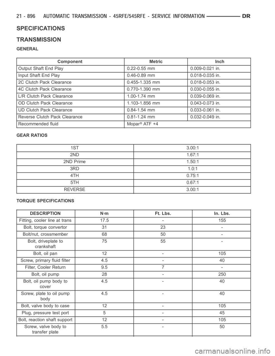
SPECIFICATIONS
TRANSMISSION
GENERAL
Component Metric Inch
Output Shaft End Play 0.22-0.55 mm 0.009-0.021 in.
Input Shaft End Play 0.46-0.89 mm 0.018-0.035 in.
2C Clutch Pack Clearance 0.455-1.335 mm 0.018-0.053 in.
4C Clutch Pack Clearance 0.770-1.390 mm 0.030-0.055 in.
L/R Clutch Pack Clearance 1.00-1.74 mm 0.039-0.069 in.
OD Clutch Pack Clearance 1.103-1.856 mm 0.043-0.073 in.
UD Clutch Pack Clearance 0.84-1.54 mm 0.033-0.061 in.
Reverse Clutch Pack Clearance 0.81-1.24 mm 0.032-0.049 in.
Recommended fluid Mopar
AT F + 4
GEAR RATIOS
1ST 3.00:1
2ND 1.67:1
2ND Prime 1.50:1
3RD 1.0:1
4TH 0.75:1
5TH 0.67:1
REVERSE 3.00:1
TORQUE SPECIFICATIONS
DESCRIPTION Nꞏm Ft. Lbs. In. Lbs.
Fitting, cooler line at trans 17.5 - 155
Bolt, torque convertor 31 23 -
Bolt/nut, crossmember 68 50 -
Bolt, driveplate to
crankshaft75 55 -
Bolt, oil pan 12 - 105
Screw, primary fluid filter 4.5 - 40
Filter, Cooler Return 9.5 7 -
Bolt, oil pump 28 - 250
Bolt, oil pump body to
cover4.5 - 40
Screw, plate to oil pump
body4.5 - 40
Bolt, valve body to case 12 - 105
Plug, pressure test port 5 - 45
Bolt, reaction shaft support 12 - 105
Screw, valve body to
transfer plate5.5 - 50
Page 3482 of 5267
CONVERTER-TORQUE
DESCRIPTION
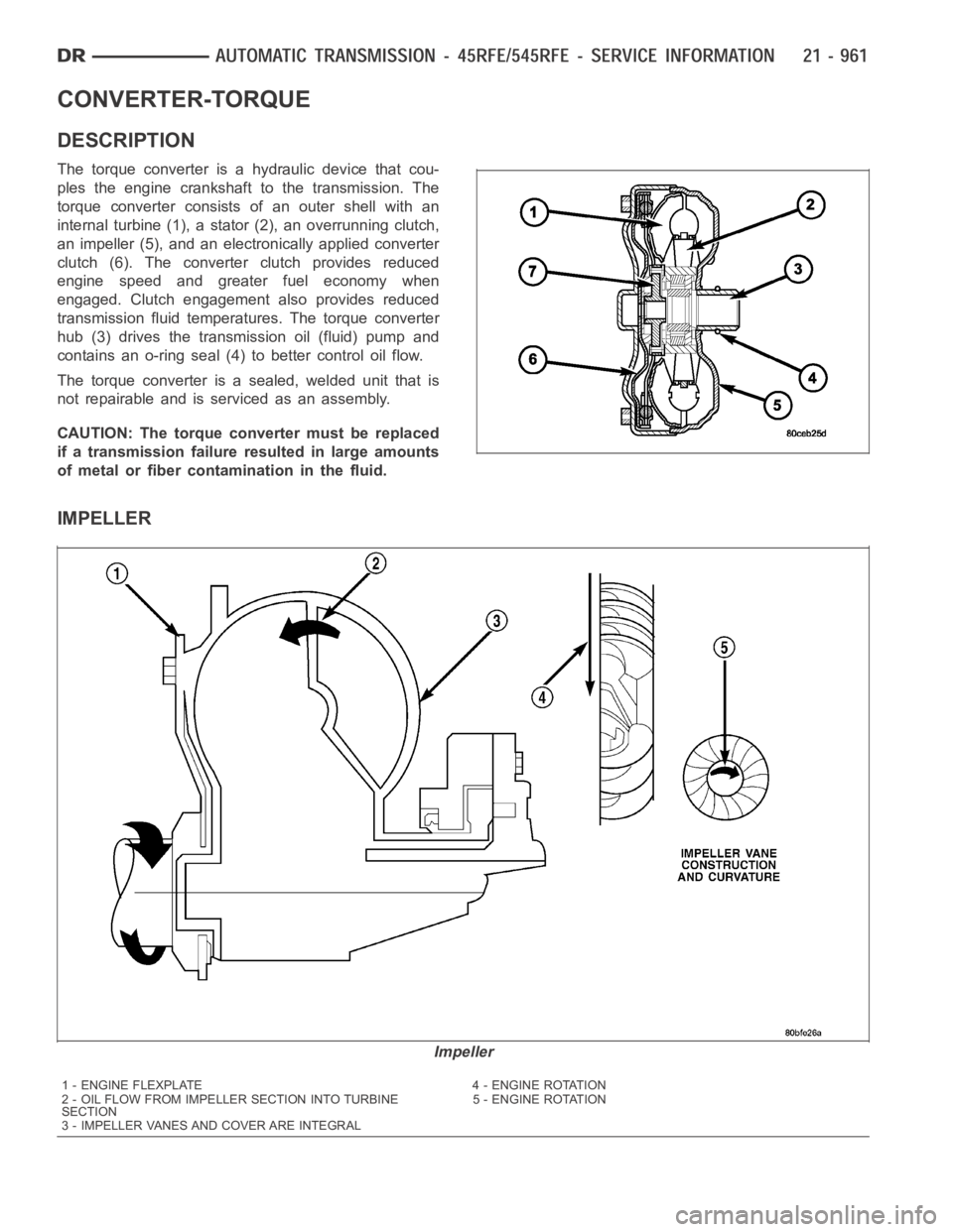
The torque converter is a hydraulic device that cou-
ples the engine crankshaft to the transmission. The
torque converter consists of an outer shell with an
internal turbine (1), a stator (2), an overrunning clutch,
an impeller (5), and an electronically applied converter
clutch (6). The converterclutch provides reduced
engine speed and greater fuel economy when
engaged. Clutch engagement also provides reduced
transmission fluid temperatures. The torque converter
hub (3) drives the transmission oil (fluid) pump and
contains an o-ring seal (4) to better control oil flow.
The torque converter is a sealed, welded unit that is
not repairable and is serviced as an assembly.
CAUTION: The torque converter must be replaced
if a transmission failure resulted in large amounts
of metal or fiber contamination in the fluid.
IMPELLER
Impeller
1 - ENGINE FLEXPLATE 4 - ENGINE ROTATION
2 - OIL FLOW FROM IMPELLER SECTION INTO TURBINE
SECTION5 - ENGINE ROTATION
3 - IMPELLER VANES AND COVER ARE INTEGRAL
Page 3792 of 5267
OPERATION
The application of each driving or holding component is controlled by the valve body based upon the manual lever
position, throttle pressure, and governor pressure. The governor pressure is a variable pressure input to the valve
body and is one of the signals that a shift is necessary. First through fourth gear are obtained by selectively apply-
ing and releasing the different clutches and bands. Engine power is thereby routed to the various planetary gear
assemblies which combine with the overrunning clutch assemblies to generate the different gear ratios. The torque
converter clutch is hydraulically applied and is released when fluid is vented from the hydraulic circuit by the torque
converter control (TCC) solenoid on the valve body. The torque converter clutch is controlled by the Powertrain
Control Module (PCM). The torque converter clutch engages in fourth gear,and in third gear under various condi-
tions, such as when the O/D switch is OFF, when the vehicle is cruising on a level surface after the vehicle has
warmed up. The torque converter clutch can also be engaged in the MANUAL SECOND gear position if high trans-
mission temperatures are sensed by the PCM. The torque converter clutch will disengage momentarily when an
increase in engine load is sensed by the PCM, such as when the vehicle beginsto go uphill or the throttle pressure
is increased. The torque converter clutch feature increases fuel economyand reduces the transmission fluid tem-
perature.
Since the overdrive clutch is applied in fourth gear only and the direct clutch is applied in all ranges except fourth
gear, the transmission operation for park, neutral, and first through third gear will be described first. Once these
powerflows are described, the third to fourth shift sequence will be described.
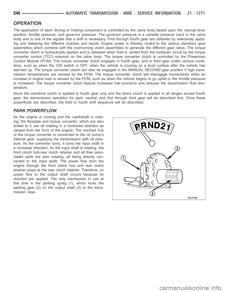
PARK POWERFLOW
As the engine is running and the crankshaft is rotat-
ing, the flexplate and torque converter, which are also
bolted to it, are all rotating in a clockwise direction as
viewed from the front of the engine. The notched hub
of the torque converter is connected to the oil pump’s
internal gear, supplying the transmission with oil pres-
sure. As the converter turns, it turns the input shaft in
a clockwise direction. As the input shaft is rotating, the
front clutch hub-rear clutch retainer and all their asso-
ciated parts are also rotating, all being directly con-
nected to the input shaft. The power flow from the
engine through the front clutch hub and rear clutch
retainer stops at the rear clutch retainer. Therefore, no
power flow to the output shaft occurs because no
clutches are applied. The only mechanism in use at
this time is the parking sprag (1), which locks the
parking gear (2) on the output shaft (3) to the trans-
mission case.
Page 3815 of 5267
REMOVAL
NOTE: The overdrive unit can be removed and serviced separately. It is not necessary to remove the entire
transmission assembly to perform overdrive unit repairs.
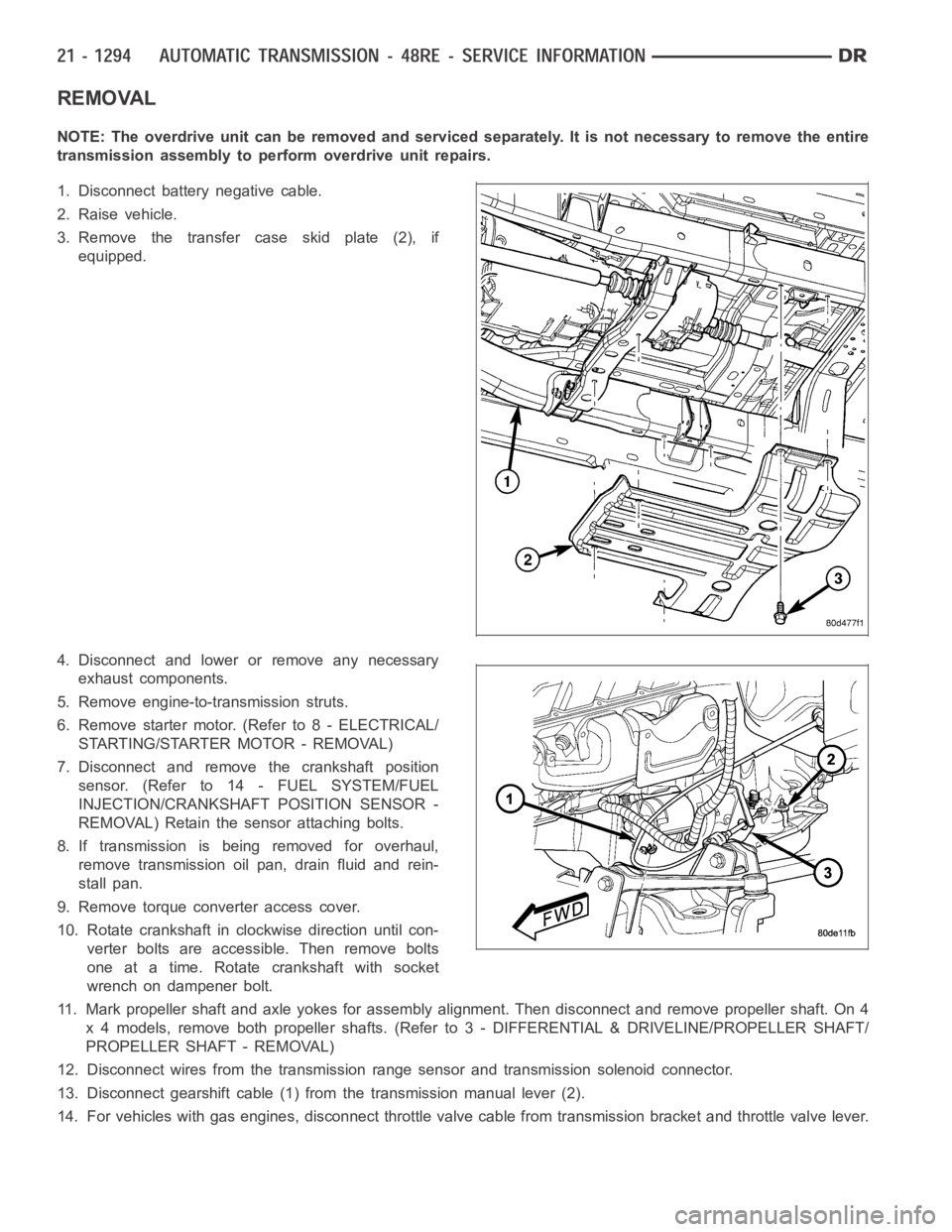
1. Disconnect battery negative cable.
2. Raise vehicle.
3. Remove the transfer case skid plate (2), if
equipped.
4. Disconnect and lower or remove any necessary
exhaust components.
5. Remove engine-to-transmission struts.
6. Remove starter motor. (Refer to 8 - ELECTRICAL/
STARTING/STARTER MOTOR - REMOVAL)
7. Disconnect and remove the crankshaft position
sensor. (Refer to 14 - FUEL SYSTEM/FUEL
INJECTION/CRANKSHAFT POSITION SENSOR -
REMOVAL) Retain the sensor attaching bolts.
8. If transmission is being removed for overhaul,
remove transmission oil pan, drain fluid and rein-
stall pan.
9. Remove torque converter access cover.
10. Rotate crankshaft in clockwise direction until con-
verter bolts are accessible. Then remove bolts
one at a time. Rotate crankshaft with socket
wrench on dampener bolt.
11. Mark propeller shaft and axle yokes for assembly alignment. Then disconnect and remove propeller shaft. On 4
x 4 models, remove both propeller shafts. (Refer to 3 - DIFFERENTIAL & DRIVELINE/PROPELLER SHAFT/
PROPELLER SHAFT - REMOVAL)
12. Disconnect wires from the transmission range sensor and transmissionsolenoid connector.
13. Disconnect gearshift cable (1) from the transmission manual lever (2).
14. For vehicles with gas engines, disconnect throttle valve cable from transmission bracket andthrottle valve lever.
Page 3838 of 5267
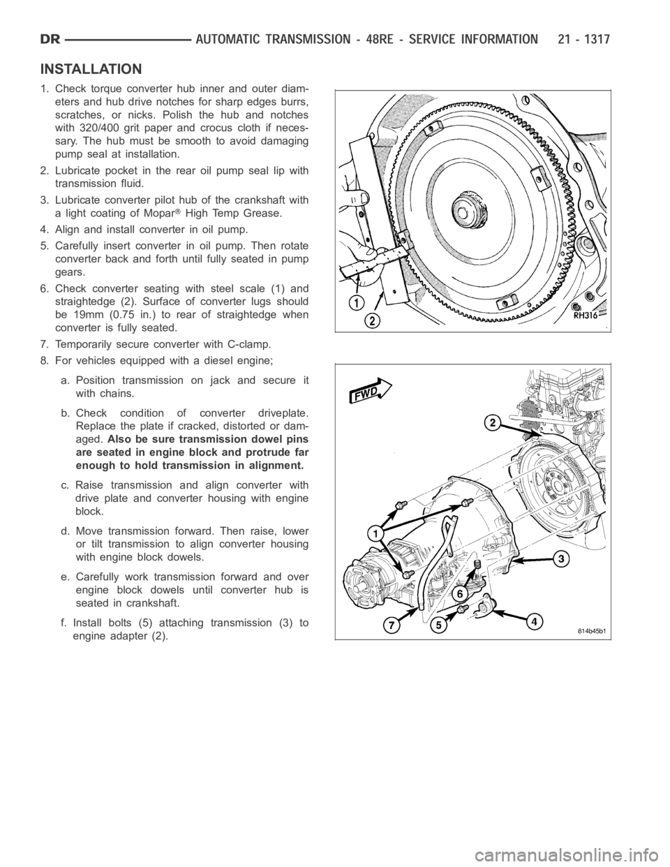
INSTALLATION
1. Check torque converter hub inner and outer diam-
eters and hub drive notches for sharp edges burrs,
scratches, or nicks. Polish the hub and notches
with 320/400 grit paper and crocus cloth if neces-
sary. The hub must be smooth to avoid damaging
pump seal at installation.
2. Lubricate pocket in the rear oil pump seal lip with
transmission fluid.
3. Lubricate converter pilot hub of the crankshaft with
a light coating of Mopar
High Temp Grease.
4. Align and install converter in oil pump.
5. Carefully insert converter in oil pump. Then rotate
converter back and forth until fully seated in pump
gears.
6. Check converter seating with steel scale (1) and
straightedge (2). Surface of converter lugs should
be 19mm (0.75 in.) to rear of straightedge when
converter is fully seated.
7. Temporarily secure converter with C-clamp.
8. For vehicles equipped with a diesel engine;
a. Position transmission on jack and secure it
with chains.
b. Check condition of converter driveplate.
Replace the plate if cracked, distorted or dam-
aged.Also be sure transmission dowel pins
are seated in engine block and protrude far
enough to hold transmission in alignment.
c. Raise transmission and align converter with
drive plate and converter housing with engine
block.
d. Move transmission forward. Then raise, lower
or tilt transmission to align converter housing
with engine block dowels.
e. Carefully work transmission forward and over
engine block dowels until converter hub is
seated in crankshaft.
f. Install bolts (5) attaching transmission (3) to
engine adapter (2).
Page 3839 of 5267

9. For vehicles equipped with a gas engine;
a. Position transmission on jack and secure it
with chains.
b. Check condition of converter driveplate.
Replace the plate if cracked, distorted or dam-
aged.Also be sure transmission dowel pins
are seated in engine block and protrude far
enough to hold transmission in alignment.
c. Raise transmission and align converter with
drive plate and converter housing with engine
block.
d. Move transmission forward. Then raise, lower
or tilt transmission to align converter housing
with engine block dowels.
e. Carefully work transmission forward and over
engine block dowels until converter hub is
seated in crankshaft.
f. Install bolts (1) attaching transmission (3) to
engine (2).
10. Install rear support.
11. Install the rear transmission crossmember.
12. Lower transmission onto crossmember and install
bolts attaching transmission mount to crossmem-
ber.
13. Remove engine support fixture.
14. Install the transfer case, if equipped. (Refer to 21
- TRANSMISSION AND TRANSFER CASE/
TRANSFER CASE - INSTALLATION)
15. Install crankshaft position sensor. (Refer to 14 -
FUEL SYSTEM/FUEL INJECTION/CRANKSHAFT
POSITION SENSOR - INSTALLATION)
16. Connect gearshift cable (1) and throttle cable (gas
engines only) to transmission.
Page 3858 of 5267
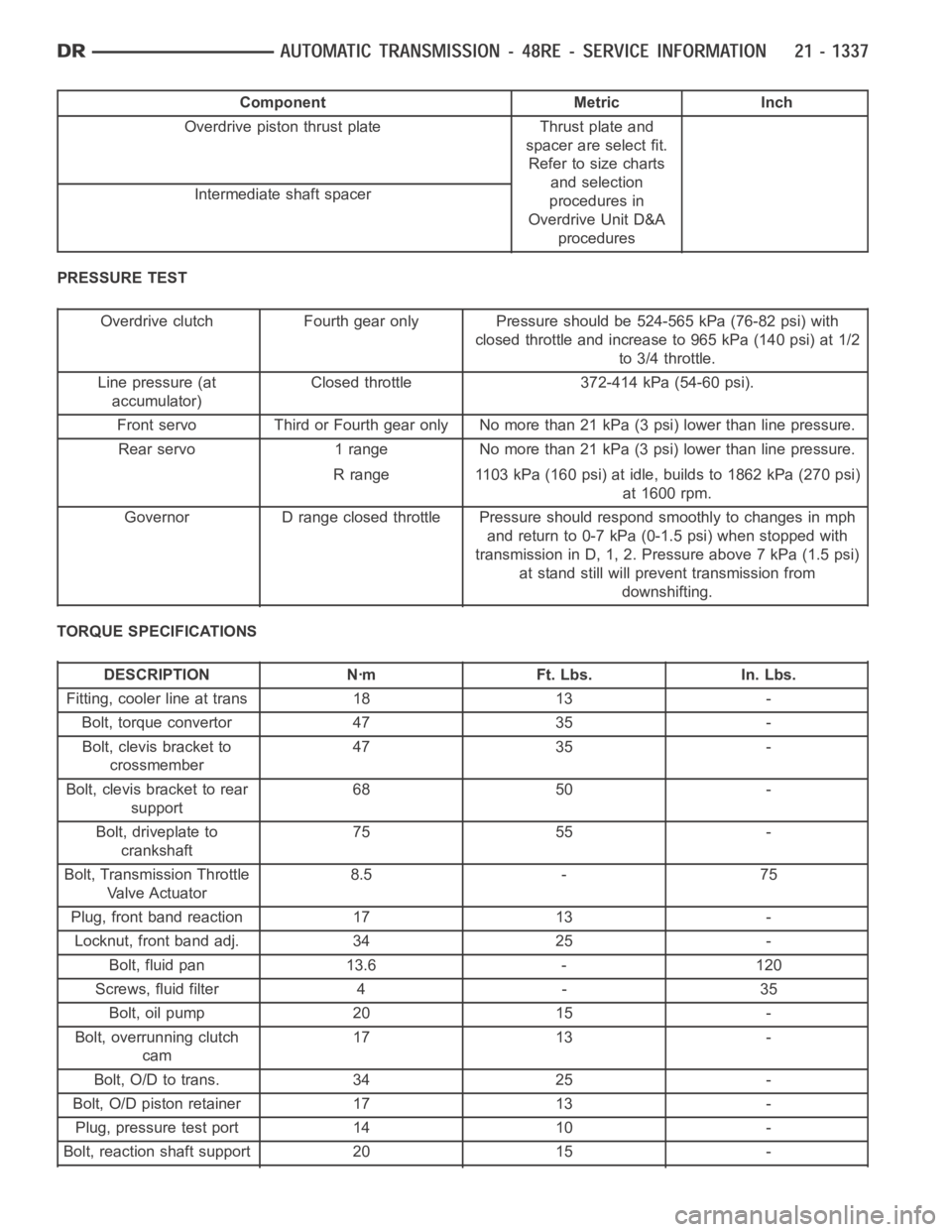
Component Metric Inch
Overdrive piston thrust plate Thrust plate and
spacer are select fit.
Refer to size charts
and selection
procedures in
Overdrive Unit D&A
procedures Intermediateshaft spacer
PRESSURE TEST
Overdrive clutch Fourth gear only Pressure should be 524-565 kPa (76-82 psi) with
closed throttle and increase to 965 kPa (140 psi) at 1/2
to 3/4 throttle.
Line pressure (at
accumulator)Closed throttle 372-414 kPa (54-60 psi).
Front servo Third or Fourth gear only No more than 21 kPa (3 psi) lower than line pressure.
Rearservo 1range Nomorethan21kPa(3psi)lowerthanlinepressure.
R range 1103 kPa (160 psi) at idle, builds to 1862 kPa (270 psi)
at 1600 rpm.
Governor D range closed throttle Pressure should respond smoothly to changes in mph
andreturnto0-7kPa(0-1.5psi)whenstoppedwith
transmission in D, 1, 2. Pressure above 7 kPa (1.5 psi)
at stand still will prevent transmission from
downshifting.
TORQUE SPECIFICATIONS
DESCRIPTION Nꞏm Ft. Lbs. In. Lbs.
Fitting, cooler line at trans 18 13 -
Bolt, torque convertor 47 35 -
Bolt, clevis bracket to
crossmember47 35 -
Bolt, clevis bracket to rear
support68 50 -
Bolt, driveplate to
crankshaft75 55 -
Bolt, Transmission Throttle
Va l v e A c t u a t o r8.5 - 75
Plug, front band reaction 17 13 -
Locknut, front band adj. 34 25 -
Bolt, fluid pan 13.6 - 120
Screws, fluid filter 4 - 35
Bolt, oil pump 20 15 -
Bolt, overrunning clutch
cam17 13 -
Bolt, O/D to trans. 34 25 -
Bolt, O/D piston retainer 17 13 -
Plug, pressure test port 14 10 -
Bolt, reaction shaft support 20 15 -
Page 3952 of 5267
CONVERTER-TORQUE
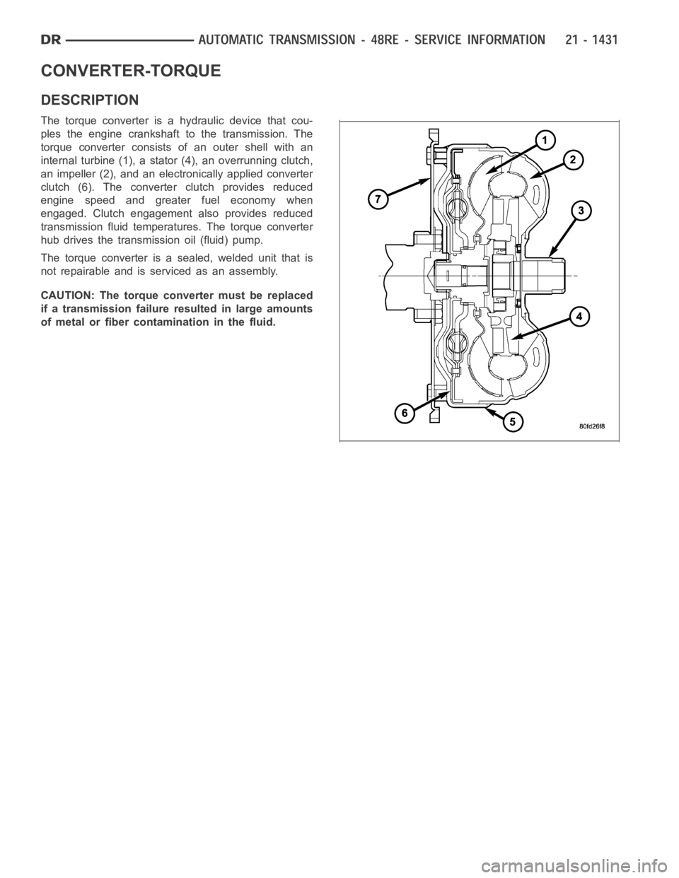
DESCRIPTION
The torque converter is a hydraulic device that cou-
ples the engine crankshaft to the transmission. The
torque converter consists of an outer shell with an
internal turbine (1), a stator (4), an overrunning clutch,
an impeller (2), and an electronically applied converter
clutch (6). The converterclutch provides reduced
engine speed and greater fuel economy when
engaged. Clutch engagement also provides reduced
transmission fluid temperatures. The torque converter
hub drives the transmission oil (fluid) pump.
The torque converter is a sealed, welded unit that is
not repairable and is serviced as an assembly.
CAUTION: The torque converter must be replaced
if a transmission failure resulted in large amounts
of metal or fiber contamination in the fluid.