Page 2482 of 5267
PUMP
DESCRIPTION
CAUTION: MOPARATF+4 is to be used in the power steering system. No other power steering or auto-
matic transmission fluid is to be used in the system. Damage may result to the power steering pump and
system if any other fluid is used, and do not overfill.
The pump is connected to the steering gear via the pressure hose and the return hose. The pump shaft has a
pressed-on pulley that is belt driven by the crankshaft pulley.
All vehicles are equipped with a power steering fluid cooler.
NOTE: Power steering pumps are not interchangeable with pumps installed on other vehicles.
OPERATION
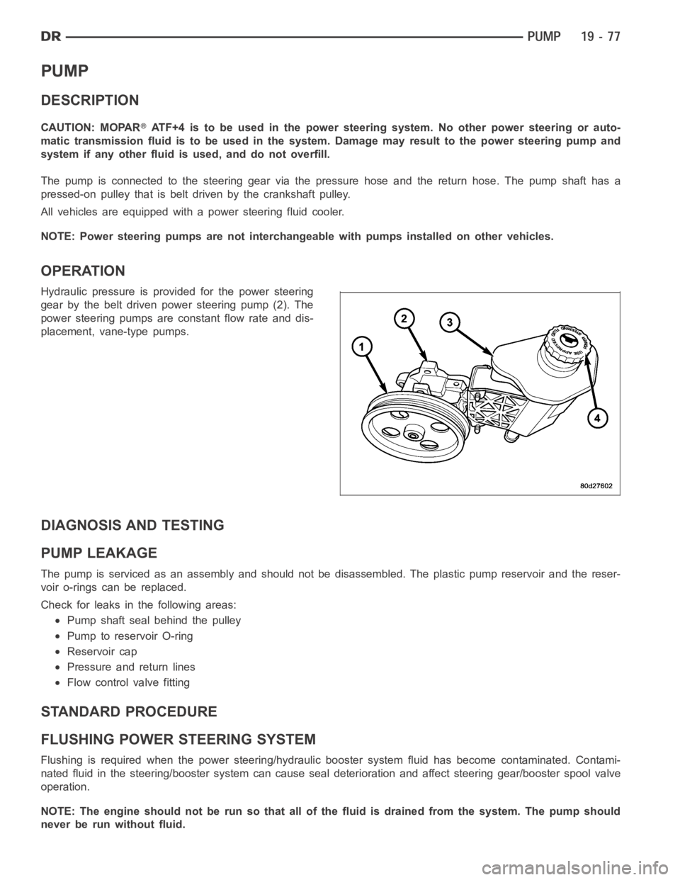
Hydraulic pressure is provided for the power steering
gear by the belt driven power steering pump (2). The
power steering pumps are constant flow rate and dis-
placement, vane-type pumps.
DIAGNOSIS AND TESTING
PUMP LEAKAGE
The pump is serviced as an assembly and should not be disassembled. The plastic pump reservoir and the reser-
voir o-rings can be replaced.
Check for leaks in the following areas:
Pump shaft seal behind the pulley
Pump to reservoir O-ring
Reservoir cap
Pressure and return lines
Flow control valve fitting
STANDARD PROCEDURE
FLUSHING POWER STEERING SYSTEM
Flushing is required when the power steering/hydraulic booster system fluid has become contaminated. Contami-
nated fluid in the steering/booster system can cause seal deterioration and affect steering gear/booster spool valve
operation.
NOTE: The engine should not be run so that all of the fluid is drained from thesystem. The pump should
never be run without fluid.
Page 2927 of 5267
16. Remove the starter motor.
17. Remove the engine to transmission collar.
18. Rotate crankshaft in clockwise direction until con-
verter bolts are accessible. Then remove bolts
one at a time. Rotate crankshaft with socket
wrench on dampener bolt.
19. Disconnect the transmission vent hose from the
transmission.
20. Remove transfer case. (Refer to 21 - TRANSMIS-
SION/TRANSFER CASE - REMOVAL)
21. Support rear of engine with safety stand or jack.
22. Raise transmission slightly with service jack to
relieve load on crossmember and supports.
23. Remove bolts securing rear support and cushion
to transmission and crossmember.
24. Remove bolts attaching crossmember to frame
and remove crossmember.
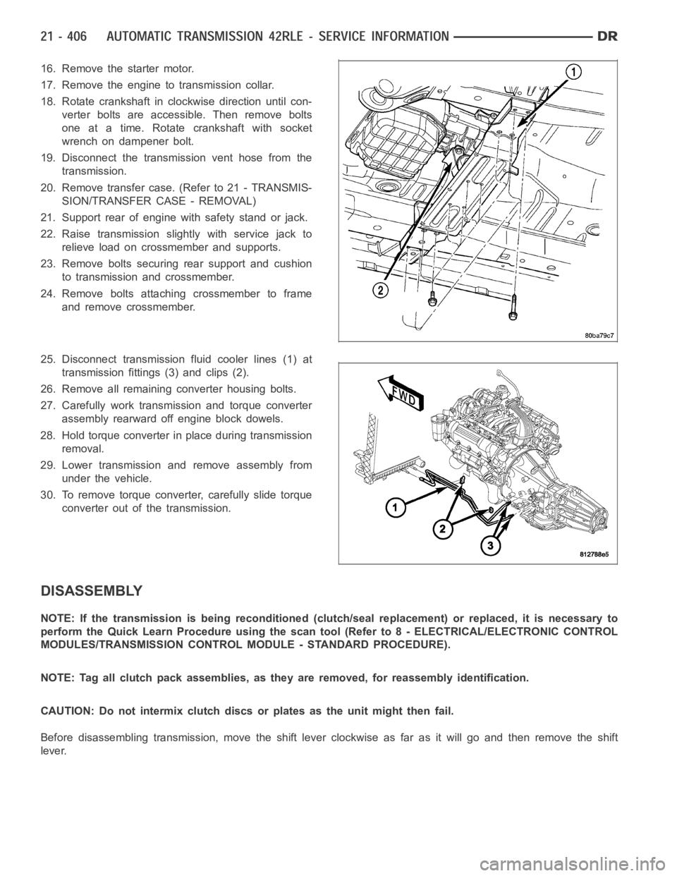
25. Disconnect transmission fluid cooler lines (1) at
transmission fittings (3) and clips (2).
26. Remove all remaining converter housing bolts.
27. Carefully work transmission and torque converter
assembly rearward off engine block dowels.
28. Hold torque converter in place during transmission
removal.
29. Lower transmission and remove assembly from
under the vehicle.
30. To remove torque converter, carefully slide torque
converter out of the transmission.
DISASSEMBLY
NOTE: If the transmission is being reconditioned (clutch/seal replacement) or replaced, it is necessary to
perform the Quick Learn Procedure using the scan tool (Refer to 8 - ELECTRICAL/ELECTRONIC CONTROL
MODULES/TRANSMISSION CONTROL MODULE - STANDARD PROCEDURE).
NOTE: Tag all clutch pack assemblies, as they are removed, for reassembly identification.
CAUTION: Do not intermix clutch discs or plates as the unit might then fail.
Before disassembling transmission, move the shift lever clockwise as faras it will go and then remove the shift
lever.
Page 2972 of 5267
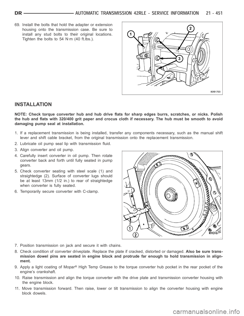
69. Install the bolts that hold the adapter or extension
housing onto the transmission case. Be sure to
install any stud bolts to their original locations.
Tighten the bolts to 54 Nꞏm (40 ft.lbs.).
INSTALLATION
NOTE: Check torque converter hub and hub drive flats for sharp edges burrs,scratches, or nicks. Polish
the hub and flats with 320/400 grit paper and crocus cloth if necessary. Thehub must be smooth to avoid
damaging pump seal at installation.
1. If a replacement transmission is being installed, transfer any components necessary, such as the manual shift
lever and shift cable bracket, from the original transmission onto the replacement transmission.
2. Lubricate oil pump seal lip with transmission fluid.
3. Align converter and oil pump.
4. Carefully insert converter in oil pump. Then rotate
converter back and forth until fully seated in pump
gears.
5. Check converter seating with steel scale (1) and
straightedge (2). Surface of converter lugs should
be at least 13mm (1/2 in.) to rear of straightedge
when converter is fully seated.
6. Temporarily secure converter with C-clamp.
7. Position transmission on jack and secure it with chains.
8. Check condition of converter driveplate. Replace the plate if cracked,distorted or damaged.Also be sure trans-
mission dowel pins are seated in engine block and protrude far enough to holdtransmissioninalign-
ment.
9. Apply a light coating of Mopar
High Temp Grease to the torque converter hub pocket in the rear pocket of the
engine’s crankshaft.
10. Raise transmission and align the torque converter with the drive plateand transmission converter housing with
the engine block.
11. Move transmission forward. Then raise, lower or tilt transmission to align the converter housing with engine
block dowels.
Page 2973 of 5267
12. Carefully work transmission forward and over engine block dowels until converter hub is seated in crankshaft.
Verify that no wires, or the transmission vent hose, have become trapped between the engine block and the
transmission.
13. Install two bolts to attach the transmission to the engine.
14. Install remaining torque converter housing to engine bolts. Tighten to 68 Nꞏm (50 ft.lbs.).
15. Install transfer case, if equipped. Tighten transfer case nuts to 35 Nꞏm (26 ft.lbs.).
16. Install rear transmission crossmember. Tighten crossmember to framebolts to 68 Nꞏm (50 ft.lbs.).
17. Install rear support to transmission. Tighten bolts to 47 Nꞏm (35 ft.lbs.).
18. Lower transmission onto crossmember and install bolts attaching transmission mount to crossmember. Tighten
clevis bracket to crossmember bolts to 47 Nꞏm (35 ft.lbs.). Tighten the clevis bracket to rear support bolt to 68
Nꞏm (50 ft.lbs.).
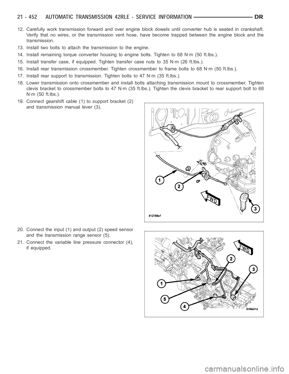
19. Connect gearshift cable (1) to support bracket (2)
and transmission manual lever (3).
20. Connect the input (1) and output (2) speed sensor
and the transmission range sensor (5).
21. Connect the variable line pressure connector (4),
if equipped.
Page 3054 of 5267
SEAL-OIL PUMP
REMOVAL
1. Remove the transmission from the vehicle (Refer to 21 - TRANSMISSION/AUTOMATIC - 42RLE - REMOVAL).
2. Remove the torque converter from the transmission bellhousing.
3. Use a screw mounted in a slide hammer to remove oil pump seal.
INSTALLATION
1. Clean and inspect oil pump seal seat. Then install seal using Seal Installer C-4193-A.
2. Clean and inspect torque converter hub. If nicks, scratches or hub wear are found, torque converter replacement
will be required.
CAUTION: If the torque converter isbeing replaced, apply a light coating of grease to the crankshaft pilot
hole. Also inspect the engine drive plate for cracks. If any cracks are found replace the drive plate. Do not
attempt to repair a cracked drive plate. Always use new torque converter todrive plate bolts.
3. Apply a light film of transmission oil to the torque converter hub and oilseal lips. Then install torque converter
into transmission. Be sure that the hub lugs mesh with the front pump lugs when installing.
4. Reinstall the transmission into the vehicle. (Refer to 21 - TRANSMISSION/TRANSAXLE/AUTOMATIC - 42RLE -
INSTALLATION)
Page 3063 of 5267
CONVERTER-TORQUE
DESCRIPTION
The torque converter is a hydraulic device that cou-
ples the engine crankshaft to the transmission. The
torque converter consists of an outer shell with an
internal turbine (1), a stator (4), an overrunning clutch,
an impeller (2) and an electronically applied converter
clutch (6). The converterclutch provides reduced
engine speed and greater fuel economy when
engaged. Clutch engagement also provides reduced
transmission fluid temperatures. The torque converter
hub drives the transmission oil (fluid) pump.
The torque converter is a sealed, welded unit that is
not repairable and is serviced as an assembly.
CAUTION: The torque converter must be replaced
if a transmission failure resulted in large amounts
of metal or fiber contamination in the fluid.
Page 3373 of 5267
8. Remove the exhaust support bracket from the rear
of the transmission.
9. Disconnect and lower or remove any necessary
exhaust components.
10. Remove the starter motor.
11. Rotate crankshaft in clockwise direction until con-
verter bolts are accessible. Then remove bolts
one at a time. Rotate crankshaft with socket
wrench on dampener bolt.
12. Disengage the output speed sensor connector
from the output speed sensor (2).
13. Disengage the input speed sensor connector from
the input speed sensor (2).
14. Disengage the transmission solenoid/TRS assem-
bly connector from the transmission solenoid/TRS
assembly (2).
Page 3392 of 5267
INSTALLATION
1. Check torque converter hub and hub drive flats for
sharp edges burrs, scratches, or nicks. Polish the
hub and flats with 320/400 grit paper and crocus
cloth if necessary. Verify that the converter hub
o-ring is properly installed and is free of any debris.
The hub must be smooth to avoid damaging pump
seal at installation.
2. If a replacement transmission is being installed,
transfer any components necessary, such as the
manual shift lever and shift cable bracket, from the
original transmission onto the replacement trans-
mission.
3. Lubricate oil pump seal lip with transmission fluid.
4. Align converter and oil pump.
5. Carefully insert converter in oil pump. Then rotate
converter back and forth until fully seated in pump
gears.
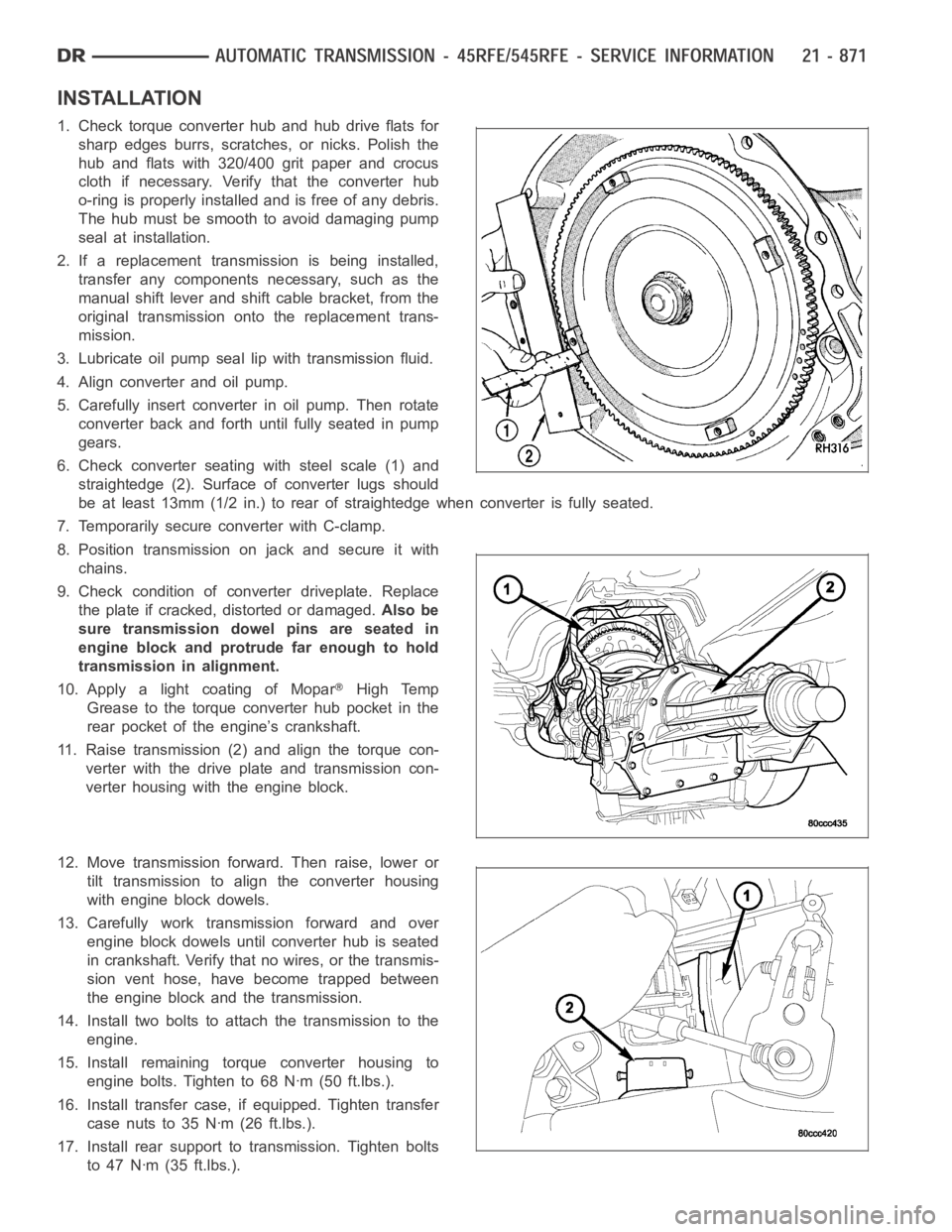
6. Check converter seating with steel scale (1) and
straightedge (2). Surface of converter lugs should
be at least 13mm (1/2 in.) to rear of straightedge when converter is fully seated.
7. Temporarily secure converter with C-clamp.
8. Position transmission on jack and secure it with
chains.
9. Check condition of converter driveplate. Replace
the plate if cracked, distorted or damaged.Also be
sure transmission dowel pins are seated in
engine block and protrude far enough to hold
transmission in alignment.
10. Apply a light coating of Mopar
High Temp
Grease to the torque converter hub pocket in the
rear pocket of the engine’s crankshaft.
11. Raise transmission (2) and align the torque con-
verter with the drive plate and transmission con-
verter housing with the engine block.
12. Move transmission forward. Then raise, lower or
tilt transmission to align the converter housing
with engine block dowels.
13. Carefully work transmission forward and over
engine block dowels until converter hub is seated
in crankshaft. Verify that no wires, or the transmis-
sion vent hose, have become trapped between
theengineblockandthetransmission.
14. Install two bolts to attach the transmission to the
engine.
15. Install remaining torque converter housing to
engine bolts. Tighten to 68 Nꞏm (50 ft.lbs.).
16. Install transfer case, if equipped. Tighten transfer
case nuts to 35 Nꞏm (26 ft.lbs.).
17. Install rear support to transmission. Tighten bolts
to 47 Nꞏm (35 ft.lbs.).