Page 2364 of 5267
8. Carefully remove each fuel line from engine. Note position of each whileremoving.Do not bend lines while
removing.
INSTALLATION
All high-pressure fuel lines are of the same length and
inside diameter. Correct high-pressure fuel line usage
and installation is critical to smooth engine operation.
CAUTION: Anytime a high-pressure line is
removed from the engine, its fuel connector nut at
the cylinder head must first be retorqued. Refer to
Torque Specifications.
1. Tighten nuts at high pressure injector connector nut
at the cylinder head. Torque nut to 50 Nꞏm (37 ft.
lbs.).
2. Position and install fuel line support clamp (2) bolts
or nut. Tighten finger tight.
3. Position proper fuel line to proper injector on
engine. Tighten fittings hand tight at both ends of
line.
4. Tighten fuel line at cylinder head. Torque nut to 30
Nꞏm (22 ft. lbs.).
Page 2365 of 5267
5. Install engine lifting bracket (1) and bolt. Torque nut
to 77 Nꞏm (56 ft. lbs.).
6. Tighten fuel lines at fuel rail. Torque nut to 37 Nꞏm
(27 ft. lbs.).
7. Tighten clamp support to intake manifold cover.
Torque nut to 24 Nꞏm (18 ft. lbs.).
8. If fuel line at either No. 1 or No. 2 cylinder has
been replaced, install intake manifold air heater
elements to top of intake manifold. Refer to Intake
Air Heater Removal / Installation for procedures.
9. If fuel line at No. 6 cylinder has been replaced, tilt
metal bracket (shield) upward and tighten 2 bolts at
rear of cylinder head. Torque nut to 43Nꞏm (32 ft.
lbs.).
10. Connect both negative battery cables to both bat-
teries.
11. Prime fuel system. Refer to Fuel System Priming.
12. Check lines/fittings for leaks.
Page 2366 of 5267
SENSOR - FUEL PRESSURE
DESCRIPTION
The fuel pressure sensor is mounted vertically near the top/center of the fuel rail.
OPERATION
The fuel pressure sensor monitors actual high-pressure within the fuel rail. An output signal from this sensor (relat-
ing to fuel pressure) is sent to the Engine Control Module (ECM).
REMOVAL
The fuel pressure sensor (4) is mounted vertically
near the top/center of the fuel rail.
1. Disconnect electrical connector (1) at sensor.
2. Remove sensor from fuel rail.
3. Inspect sensor sealing surface.
INSTALLATION
1. Inspect fuel pressure sensor sealing surface.
2. Lubricate sensor threads with clean diesel fuel.
3. Install sensor (4) into fuel rail.
4. To prevent leaks, sensormustbe tightened to 70
Nꞏm (52 ft. lbs.).
5. Connect electrical connector to sensor.
6. Start engine and check for fuel leaks.
Page 2367 of 5267

VALVE - FUEL PRESSURE LIMITING
DESCRIPTION
The fuel pressure limiting valve is located on the top of the fuel rail.
OPERATION
Fuel pressure at the fuel rail is monitored by the fuel rail pressure sensor. If fuel pressure becomes excessive, the
pressure limiting valve opens and vents excess pressure into the fuel draincircuit.
REMOVAL
CAUTION: Cleanliness cannot be overemphasized when handling or replacingdieselfuelsystemcompo-
nents. This especially includes the fuel injectors, high-pressure fuel lines and fuel injection pump. Very tight
tolerances are used with these parts. Dirt contamination could cause rapid part wear and possible plugging
of fuel injector nozzle tip holes. This in turn could lead to possible engine misfire. Always wash/clean any
fuel system component thoroughly before disassembly and then air dry. Capor cover any open part after
disassembly. Before assembly, examine each part for dirt, grease or othercontaminants and clean if nec-
essary. When installing new parts, lubricate them with clean engine oil orclean diesel fuel only.
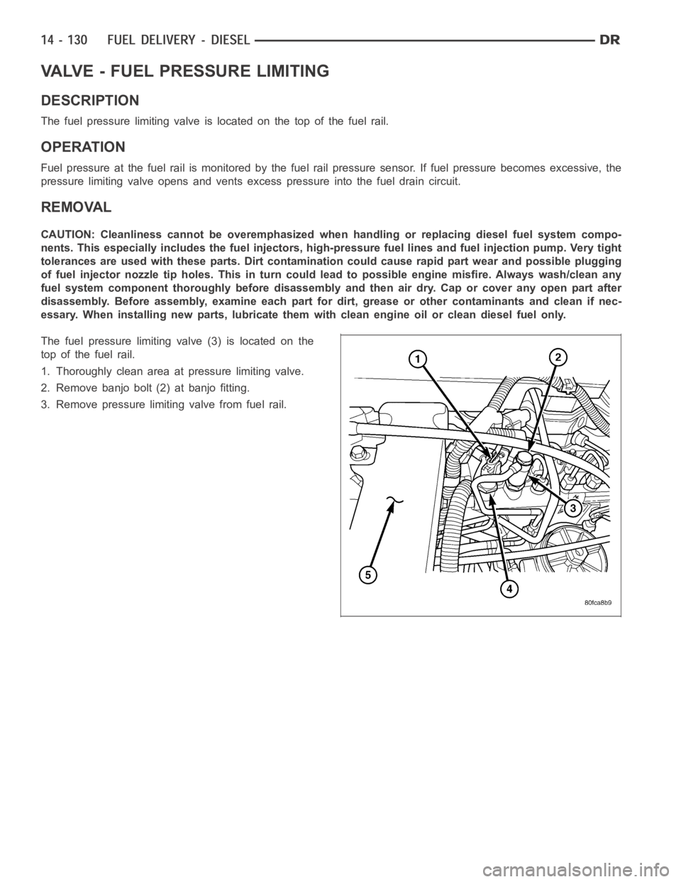
The fuel pressure limiting valve (3) is located on the
top of the fuel rail.
1. Thoroughly clean area at pressure limiting valve.
2. Remove banjo bolt (2) at banjo fitting.
3. Remove pressure limiting valve from fuel rail.
Page 2370 of 5267
INSTALLATION
1. If fuel tank is to be replaced, install fuel tank mod-
ule into tank. (Refer to 14 - FUEL SYSTEM/FUEL
DELIVERY/FUEL TANK MODULE - REMOVAL).
2. Position fuel tank (1) to hydraulic jack.
3. Raise tank until positioned near body.
4. Connect fuel tank module electrical connector at
top of tank.
5. Connect fuel supply and return lines to tank mod-
ule.
6. Continue raising tank until positioned snug to body.
7. Install and position both tank support straps (4).
Install 2 fuel tank strap nuts and tighten to 41 Nꞏm
(30 ft. lbs.).Tighten rear strap nut first.
8. Remove hydraulic jack.
9. Connect rubber fill hose to fuel fill tube and tighten
clamp.
10. Install tire / wheel (if necessary).
11. Lower vehicle.
12. Fill fuel tank with fuel.
13. Start engine and check for fuel leaks near top of module.
Page 2373 of 5267

PUMP - FUEL TRANSFER
DESCRIPTION
The fuel transfer pump (fuel lift pump) is part of the fuel pump module. The fuel pump module is located in the fuel
tank. The 12–volt electric pump is operated and controlled by the Engine Control Module (ECM). The ECM controls
a relay in the Intelligent Power Module(IPM) for transfer pump operation.
OPERATION
The purpose of the fuel transfer pump is to supply (transfer) a low-pressure fuel source:fromthe fuel tank,through
the fuel filter/water separator andtothe fuel injection pump. Here, the low-pressure is raised to a high-pressure by
the fuel injection pump for operation of the high-pressure fuel injectors. Check valves within the pump, control direc-
tion of fuel flow and prevent fuel bleed-back during engine shut down.
Maximum current flow to the pump is 5 amperes.
With the engine running, the pump has a 100 percent duty-cycle.
The transfer pump is self-priming: When the key is first turned on (withoutcranking engine), the pump will operate
for approximately 2 seconds and then shut off (Note: When ambient temperatures are cold enough to cause the
intake air heaters to operate, the fuel lift pump will operate during the entire intake air pre-heat cycle). The pump will
also operate for up to 25 seconds after the starter is engaged, and then disengaged and the engine is not running.
The pump shuts off immediately if the key is on and the engine stops running.
The fuel volume of the transfer pump will always provide more fuel than the fuel injection pump requires. Excess
fuel is returned from the injection pump through an overflow valve, and then back to the fuel tank.
REMOVAL
The fuel transfer pump (fuel lift pump) is a part of the fuel tank module. It is not serviced separately. Refer to Fuel
Tank Module Removal or Installation for procedures (Refer to 14 - FUEL SYSTEM/FUEL DELIVERY/FUEL TANK
MODULE - REMOVAL).
INSTALLATION
The fuel transfer pump (fuel lift pump) is a part of the fuel tank module. It is not serviced separately (Refer to 14 -
FUEL SYSTEM/FUEL DELIVERY/FUEL TANK MODULE - INSTALLATION).
Page 2375 of 5267
SENSOR-WATER IN FUEL
DESCRIPTION
The Water-In-Fuel (WIF) sensor (5) is located on the
side of the fuel filter/water separator canister.
OPERATION
The sensor sends an input to the Engine Control Module (ECM) when it senses water in the fuel filter/water sep-
arator. As the water level in the filter/separator increases, the resistance across the WIF sensor decreases. This
decreaseinresistanceissentasasignaltotheECMandcomparedtoahighwater standard value. Once the value
reaches 30 to 40 kilohms, the ECM will activate the water-in-fuel warning lamp through CCD bus circuits. This all
takes place when the ignition key is initially put in the ON position. The ECM continues to monitor the input while
the engine is running.
REMOVAL
The Water-In-Fuel (WIF) sensor is located at the side of fuel filter/waterseparator canister. (Refer to 14 - FUEL
SYSTEM/FUEL DELIVERY/FUEL TANK MODULE - INSTALLATION).
Page 2378 of 5267
SENSOR-ACCELERATOR PEDAL POSITION
DESCRIPTION
The Accelerator Pedal Position Sensor (APPS) (1) is
located inside the vehicle.It is attached to the accel-
erator pedal assembly (3).
OPERATION
The Accelerator Pedal Position Sensor (APPS) provides the Engine ControlModule (ECM) with two DC voltage
signals which change as the position of the accelerator pedal changes. Oneof the DC voltage signals will be half
the voltage of the other signal.
REMOVAL
CAUTION: Do not attempt to separate or remove the Accelerator Pedal Position Sensor (APPS) from the
accelerator pedal assembly. The APPS is replaced as an assembly along withthe pedal. If sensor is
removed from pedal, its electronic calibration may be destroyed.
1. Disconnect 6–way electrical connector at top of
APPS (2).
2. Remove APPS lower mounting bolt (4) and two
mounting nuts.
3. Remove pedal and APPS assembly from vehicle.