2006 DODGE RAM SRT-10 engine
[x] Cancel search: enginePage 2405 of 5267
SWITCH - PTO
DESCRIPTION
This Engine Control Module (ECM) input is used only on models equipped withaftermarket Power Take Off (PTO)
units.
OPERATION
This input is used only to tell the ECM that the aftermarket PTO (Power Take Off) unit has been engaged. The ECM
will disable (temporarily shut down) certain OBD II diagnostic trouble codes when the PTO unit is engaged.
Page 2407 of 5267
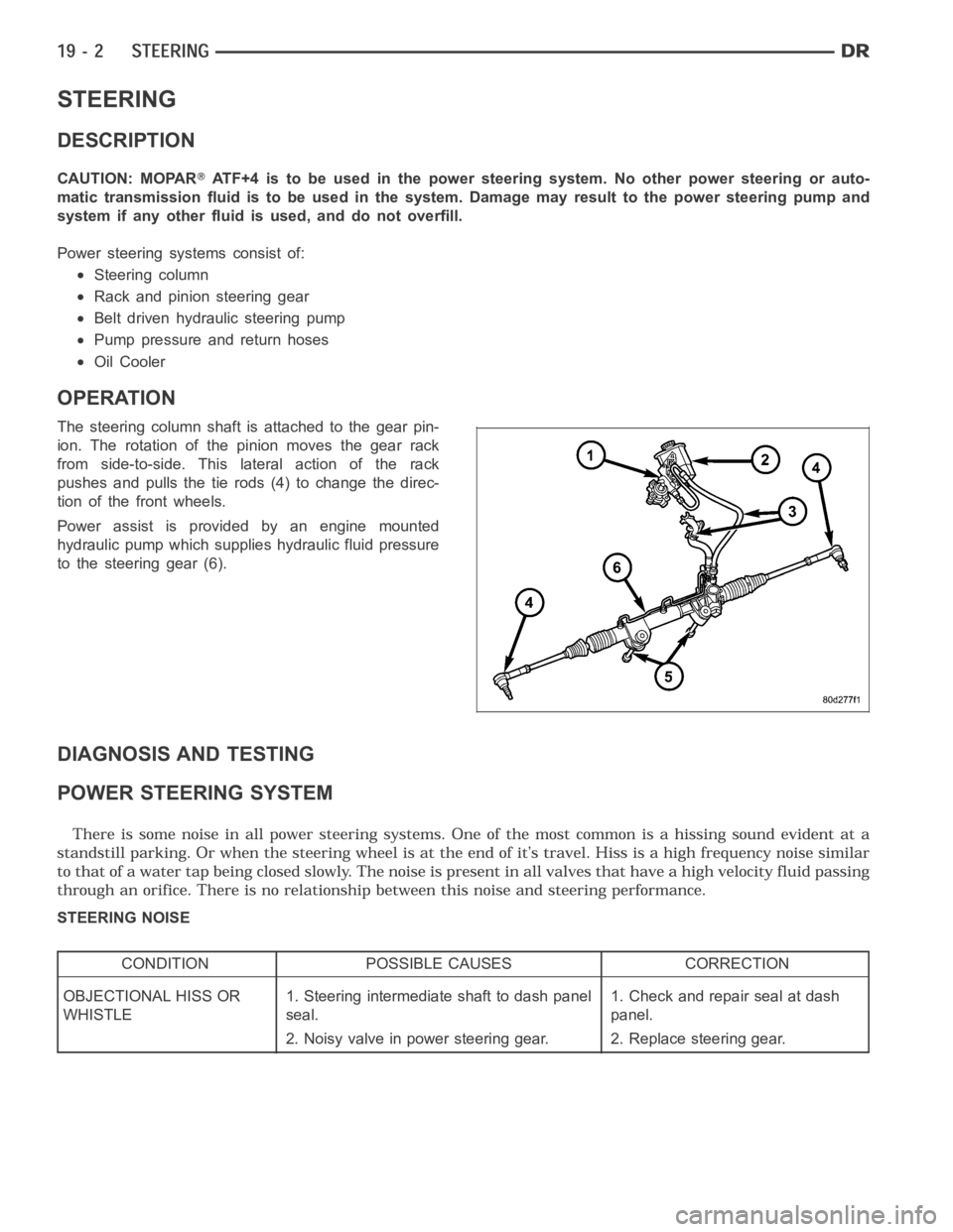
STEERING
DESCRIPTION
CAUTION: MOPARATF+4 is to be used in the power steering system. No other power steering or auto-
matic transmission fluid is to be used in the system. Damage may result to the power steering pump and
system if any other fluid is used, and do not overfill.
Power steering systems consist of:
Steering column
Rack and pinion steering gear
Belt driven hydraulic steering pump
Pump pressure and return hoses
Oil Cooler
OPERATION
The steering column shaft isattached to the gear pin-
ion. The rotation of the pinion moves the gear rack
from side-to-side. This lateral action of the rack
pushes and pulls the tie rods (4) to change the direc-
tion of the front wheels.
Power assist is provided by an engine mounted
hydraulic pump which supplies hydraulic fluid pressure
to the steering gear (6).
DIAGNOSIS AND TESTING
POWER STEERING SYSTEM
STEERING NOISE
CONDITION POSSIBLE CAUSES CORRECTION
OBJECTIONAL HISS OR
WHISTLE1. Steering intermediate shaft to dash panel
seal.1. Check and repair seal at dash
panel.
2. Noisy valve in power steering gear. 2. Replace steering gear.
Page 2410 of 5267
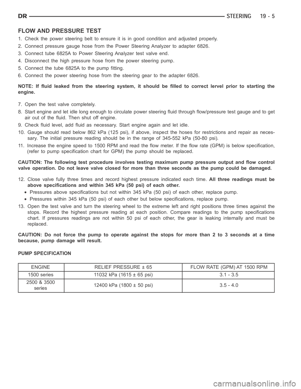
FLOW AND PRESSURE TEST
1. Check the power steering belt to ensure it is in good condition and adjusted properly.
2. Connect pressure gauge hose from the Power Steering Analyzer to adapter6826.
3. Connect tube 6825A to Power Steering Analyzer test valve end.
4. Disconnect the high pressure hose from the power steering pump.
5. Connect the tube 6825A to the pump fitting.
6. Connect the power steering hose from the steering gear to the adapter 6826.
NOTE: If fluid leaked from the steering system, it should be filled to correct lervel prior to starting the
engine.
7. Open the test valve completely.
8. Start engine and let idle long enough to circulate power steering fluid through flow/pressure test gauge and to get
air out of the fluid. Then shut off engine.
9. Check fluid level, add fluid as necessary. Start engine again and let idle.
10. Gauge should read below 862 kPa (125 psi), if above, inspect the hoses for restrictions and repair as neces-
sary. The initial pressure reading should be in the range of 345-552 kPa (50-80 psi).
11. Increase the engine speed to 1500 RPM and read the flow meter. If the flowrate (GPM) is below specification,
(refer to pump specification chart for GPM) the pump should be replaced.
CAUTION: The following test procedure involves testing maximum pump pressure output and flow control
valve operation. Do not leave valve closed for more than three seconds as the pump could be damaged.
12. Close valve fully three times and record highest pressure indicated each time.All three readings must be
above specifications and within 345 kPa (50 psi) of each other.
Pressures above specifications but not within 345 kPa (50 psi) of each other, replace pump.
Pressures within 345 kPa (50 psi) of each other but below specifications, replace pump.
13. Open the test valve and turn the steering wheel to the extreme left and right positions three times against the
stops. Record the highest pressure reading at each position. Compare readings to the pump specifications
chart. If pressures readings are not within 50 psi of each other, the gear isleaking internally and must be
replaced.
CAUTION: Do not force the pump to operate against the stops for more than 2 to3 seconds at a time
because, pump damage will result.
PUMP SPECIFICATION
ENGINE RELIEF PRESSURE ± 65 FLOW RATE (GPM) AT 1500 RPM
1500 series 11032 kPa (1615 ± 65 psi) 3.1 - 3.5
2500 & 3500
series12400 kPa (1800 ± 50 psi) 3.5 - 4.0
Page 2481 of 5267
page page
PUMP
DESCRIPTION ................................ 77
OPERATION .................................. 77
DIAGNOSIS AND TESTING
PUMP LEAKAGE ............................ 77
STANDARD PROCEDURE
FLUSHING POWER STEERING SYSTEM . . . . . 77
POWER STEERING PUMP - INITIAL
OPERATION................................ 78
REMOVAL
GAS ENGINE ............................... 79
DIESEL ENGINE............................ 79
INSTALLATION
GAS ENGINE ............................... 80
DIESEL ENGINE............................ 80
SPECIFICATIONS
TORQUE ................................... 81
FLUID
DESCRIPTION ................................ 82
STANDARD PROCEDURE
POWER STEERING FLUID LEVEL
CHECKING................................. 82
FLUID COOLER
REMOVAL .................................... 83
INSTALLATION ............................... 83
HOSES - I.F.S.
REMOVAL
RETURN HOSE - GEAR TO COOLER ......... 85PRESSURE HOSE .......................... 85
RETURN HOSE - RESERVOIR TO COOLER . . 85
INSTALLATION
RETURN HOSE - GEAR TO COOLER ......... 86
PRESSURE HOSE .......................... 86
RETURN HOSE - RESERVOIR TO COOLER . . 86
HOSES - LINK/COIL
REMOVAL
RETURN HOSE - GEAR TO COOLER ......... 87
PRESSURE HOSE .......................... 87
RETURN HOSE - RESERVOIR TO COOLER . . 87
INSTALLATION
RETURN HOSE - GEAR TO COOLER ......... 88
PRESSURE HOSE .......................... 88
RETURN HOSE - RESERVOIR TO COOLER . . 88
SWITCH-POWER STEERING PRESSURE
DESCRIPTION ................................ 89
OPERATION .................................. 89
REMOVAL - 5.7L - HD VEHICLES ONLY ......... 89
INSTALLATION - 5.7L - HD VEHICLES ONLY .... 89
PULLEY
REMOVAL .................................... 90
INSTALLATION ............................... 90
RESERVOIR
REMOVAL .................................... 91
INSTALLATION ............................... 91
Page 2482 of 5267
PUMP
DESCRIPTION
CAUTION: MOPARATF+4 is to be used in the power steering system. No other power steering or auto-
matic transmission fluid is to be used in the system. Damage may result to the power steering pump and
system if any other fluid is used, and do not overfill.
The pump is connected to the steering gear via the pressure hose and the return hose. The pump shaft has a
pressed-on pulley that is belt driven by the crankshaft pulley.
All vehicles are equipped with a power steering fluid cooler.
NOTE: Power steering pumps are not interchangeable with pumps installed on other vehicles.
OPERATION
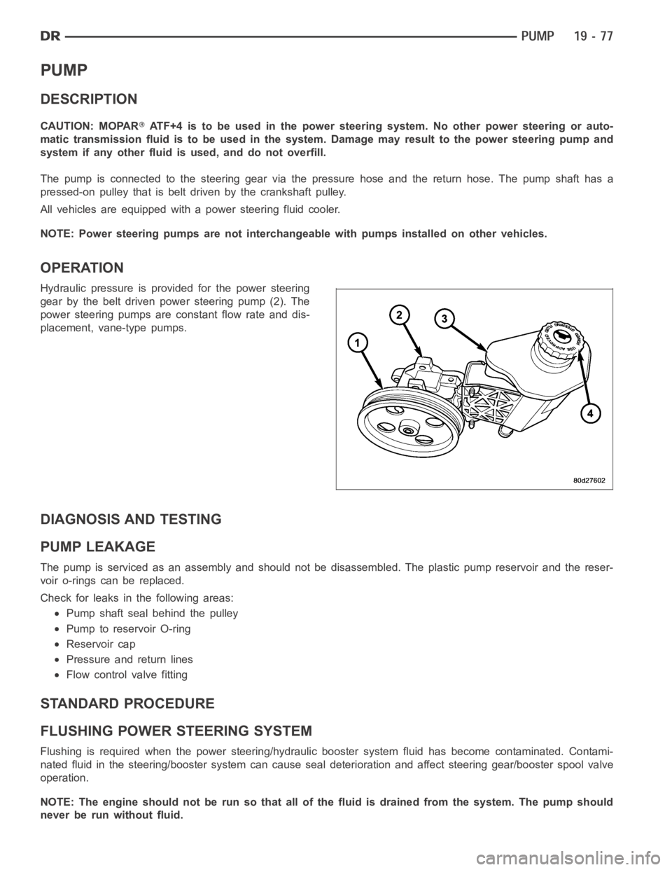
Hydraulic pressure is provided for the power steering
gear by the belt driven power steering pump (2). The
power steering pumps are constant flow rate and dis-
placement, vane-type pumps.
DIAGNOSIS AND TESTING
PUMP LEAKAGE
The pump is serviced as an assembly and should not be disassembled. The plastic pump reservoir and the reser-
voir o-rings can be replaced.
Check for leaks in the following areas:
Pump shaft seal behind the pulley
Pump to reservoir O-ring
Reservoir cap
Pressure and return lines
Flow control valve fitting
STANDARD PROCEDURE
FLUSHING POWER STEERING SYSTEM
Flushing is required when the power steering/hydraulic booster system fluid has become contaminated. Contami-
nated fluid in the steering/booster system can cause seal deterioration and affect steering gear/booster spool valve
operation.
NOTE: The engine should not be run so that all of the fluid is drained from thesystem. The pump should
never be run without fluid.
Page 2483 of 5267
1. Raise the front end of the vehicle off the ground until the wheels are freeto turn.
2. Remove the return line from the pump.
NOTE: If vehicle is equipped with a hydraulic booster remove both return lines from the pump.
3. Plug the return line port/ports at the pump.
4. Position the return line/lines into a large container to catch the fluid.
5. While an assistant is filling the pump reservoir start the engine.
6. With the engine running at idle turn the wheel back and forth.
NOTE: Do not contact or hold the wheel against the steering stops.
7. Run a quart of fluid through the system then stop the engine and install the return line/lines.
8. Fill the system with fluid and perform Steering Pump Initial Operation,(Refer to 19 - STEERING/PUMP - STAN-
DARD PROCEDURE).
9. Start the engine and run it for fifteen minutes then stop the engine.
10. Remove the return line/lines from the pump and plug the pump port/ports.
11. Pour fresh fluid into the reservoir and check the draining fluid for contamination. If the fluid is still contaminated,
then flush the system again.
12. Install the return line/lines and perform Steering Pump Initial Operation, (Refer to 19 - STEERING/PUMP -
STANDARD PROCEDURE).
POWER STEERING PUMP - INITIAL OPERATION
WARNING: THE FLUID LEVEL SHOULD BE CHECKED WITH ENGINE OFF TO PREVENT INJURYFROMMOV-
ING COMPONENTS.
CAUTION: MOPAR
ATF+4 is to be used in the power steering system. No other power steering or auto-
matic transmission fluid is to be used in the system. Damage may result to the power steering pump and
system if any other fluid is used, and do not overfill.
Wipe filler cap clean, then check the fluid level. The dipstick should indicateCOLDwhen the fluid is at normal
temperature.
1. Turn steering wheel all the way to the left.
2. Fill reservoir up to FULL HOT level and crank engine until it just starts.(DO NOT TURN STEERING WHEEL).
Then turn vehicle off. And recheck fluid level, to Full COLD.
3. Crank engine again until it just starts, (DO NOT MOVE STEERING WHEEL). and turn vehicle off. Recheck fluid
leveltoFullCOLD.
4. Turn engine on again, (DO NOT MOVE STEERING WHEEL) and let the vehicle idle for 5 minutes. If possible
apply a 20 in-Hg vacuum to the reservoir, while engine is idling.
5. Turn engine off and recheck fluid level, to FULL COLD.
6.If the Steering gear is replacedensure reservoir is at FULL HOT level, start engine and turn wheel to left. Stop
Engine and recheck fluid level to FULL HOT. Start engine and turn wheel to the right. Stop engine and check
fluid level is at FULL COLD.
7. Fill the pump fluid reservoir to the proper level and let the fluid settlefor at least two (2) minutes.
8. Start the engine. With the engine idling maintain the fluid level.
9. Raise the front wheels off the ground.
10. Slowly turn the steering wheel lock-to-lock 20 times with the engine off while checking the fluid level.
NOTE: For vehicles with long return lines or oil coolers turn wheel 40 times.
11. Lower the front wheels and let the engine idle for two minutes.
12. Turn the steering wheel in both direction and verify power assist and quiet operation of the pump.
If the fluid is extremely foamy or milky looking, allow the vehicle to standa few minutes and repeat the procedure.
Page 2484 of 5267
CAUTION: Do not run a vehicle with foamy fluid for an extended period. This may cause pump damage.
REMOVAL
GAS ENGINE
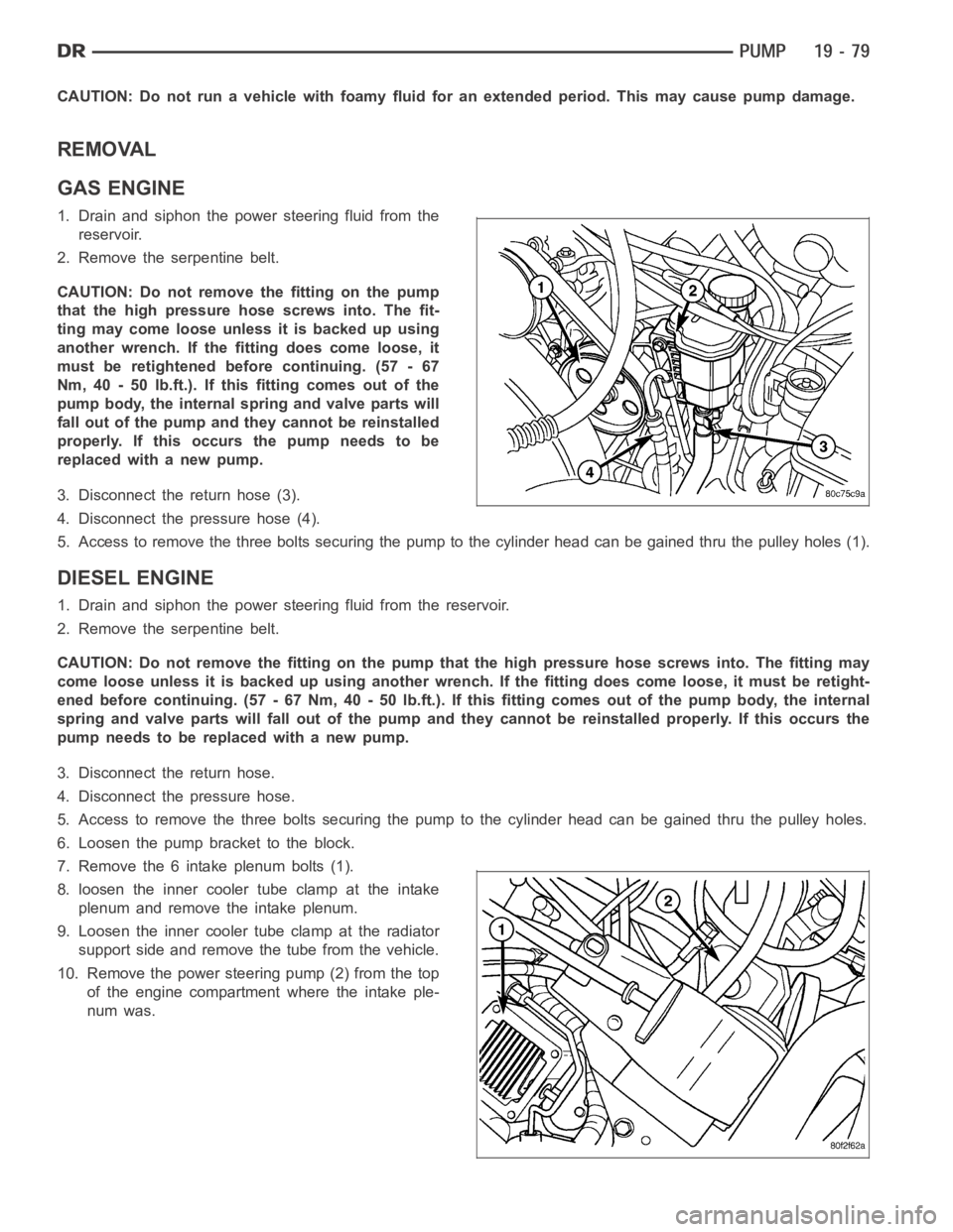
1. Drain and siphon the power steering fluid from the
reservoir.
2. Remove the serpentine belt.
CAUTION: Do not remove the fitting on the pump
that the high pressure hose screws into. The fit-
ting may come loose unless it is backed up using
another wrench. If the fitting does come loose, it
must be retightened before continuing. (57 - 67
Nm, 40 - 50 lb.ft.). If this fitting comes out of the
pump body, the internal spring and valve parts will
fall out of the pump and they cannot be reinstalled
properly. If this occurs the pump needs to be
replaced with a new pump.
3. Disconnect the return hose (3).
4. Disconnect the pressure hose (4).
5. Access to remove the three bolts securing the pump to the cylinder head can be gained thru the pulley holes (1).
DIESEL ENGINE
1. Drain and siphon the power steering fluid from the reservoir.
2. Remove the serpentine belt.
CAUTION: Do not remove the fitting on the pump that the high pressure hose screws into. The fitting may
come loose unless it is backed up using another wrench. If the fitting does come loose, it must be retight-
ened before continuing. (57 - 67 Nm, 40 - 50 lb.ft.). If this fitting comes out of the pump body, the internal
spring and valve parts will fall out of the pump and they cannot be reinstalled properly. If this occurs the
pump needs to be replaced with a new pump.
3. Disconnect the return hose.
4. Disconnect the pressure hose.
5. Access to remove the three bolts securing the pump to the cylinder head can be gained thru the pulley holes.
6. Loosen the pump bracket to the block.
7. Remove the 6 intake plenum bolts (1).
8. loosen the inner cooler tube clamp at the intake
plenum and remove the intake plenum.
9. Loosen the inner cooler tube clamp at the radiator
support side and remove the tube from the vehicle.
10. Remove the power steering pump (2) from the top
of the engine compartment where the intake ple-
num was.
Page 2485 of 5267
INSTALLATION
GAS ENGINE
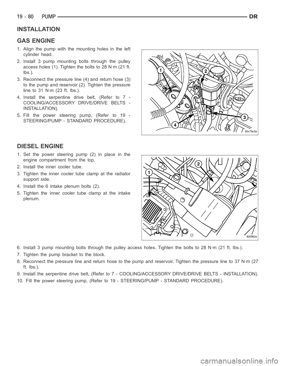
1. Align the pump with the mounting holes in the left
cylinder head.
2. Install 3 pump mounting bolts through the pulley
access holes (1). Tighten the bolts to 28 Nꞏm (21 ft.
lbs.).
3. Reconnect the pressure line (4) and return hose (3)
to the pump and reservoir (2). Tighten the pressure
line to 31 Nꞏm (23 ft. lbs.).
4. Install the serpentine drive belt, (Refer to 7 -
COOLING/ACCESSORY DRIVE/DRIVE BELTS -
INSTALLATION).
5. Fill the power steering pump, (Refer to 19 -
STEERING/PUMP - STANDARD PROCEDURE).
DIESEL ENGINE
1. Set the power steering pump (2) in place in the
engine compartment from the top.
2. Install the inner cooler tube.
3. Tighten the inner cooler tube clamp at the radiator
support side.
4. Install the 6 intake plenum bolts (2).
5. Tighten the inner cooler tube clamp at the intake
plenum.
6. Install 3 pump mounting bolts through the pulley access holes. Tighten theboltsto28Nꞏm(21ft.lbs.).
7. Tighten the pump bracket to the block.
8. Reconnect the pressure line and return hose to the pump and reservoir. Tightenthepressurelineto37Nꞏm(27
ft. lbs.).
9. Install the serpentine drive belt, (Refer to 7 - COOLING/ACCESSORY DRIVE/DRIVE BELTS - INSTALLATION).
10. Fill the power steering pump, (Refer to 19 - STEERING/PUMP - STANDARD PROCEDURE).