Page 2502 of 5267

ASSEMBLY
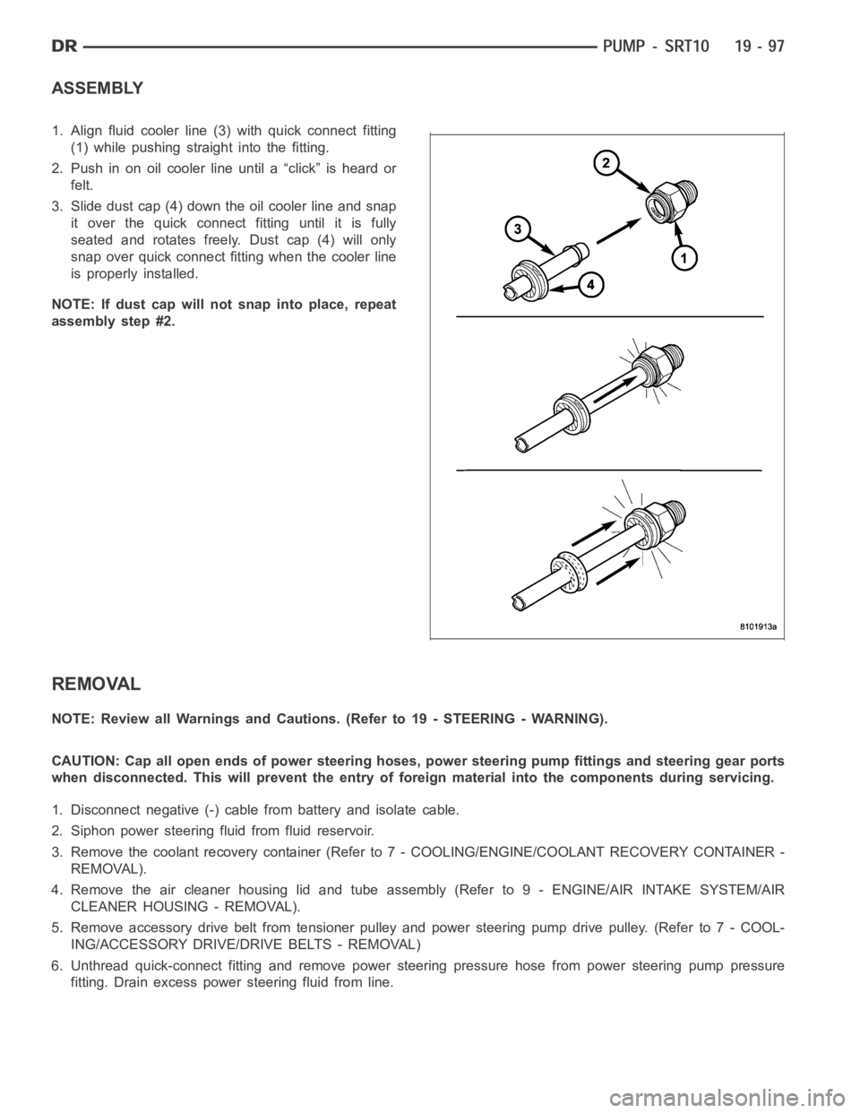
1. Align fluid cooler line (3) with quick connect fitting
(1) while pushing straight into the fitting.
2. Push in on oil cooler line until a “click” is heard or
felt.
3. Slide dust cap (4) down the oil cooler line and snap
it over the quick connect fitting until it is fully
seated and rotates freely. Dust cap (4) will only
snap over quick connect fitting when the cooler line
is properly installed.
NOTE: If dust cap will not snap into place, repeat
assembly step #2.
REMOVAL
NOTE: Review all Warnings and Cautions. (Refer to 19 - STEERING - WARNING).
CAUTION: Cap all open ends of power steering hoses, power steering pump fittings and steering gear ports
when disconnected. This will prevent the entry of foreign material into the components during servicing.
1. Disconnect negative (-) cable from battery and isolate cable.
2. Siphon power steering fluid from fluid reservoir.
3. Remove the coolant recovery container (Refer to 7 - COOLING/ENGINE/COOLANT RECOVERY CONTAINER -
REMOVAL).
4. Remove the air cleaner housing lid and tube assembly (Refer to 9 - ENGINE/AIR INTAKE SYSTEM/AIR
CLEANER HOUSING - REMOVAL).
5. Remove accessory drive belt from tensioner pulley and power steering pump drive pulley. (Refer to 7 - COOL-
ING/ACCESSORY DRIVE/DRIVE BELTS - REMOVAL)
6. Unthread quick-connect fitting and remove power steering pressure hose from power steering pump pressure
fitting. Drain excess power steering fluid from line.
Page 2503 of 5267
7. Disconnect A/C clutch coil wire connector (2).
8. Remove return hose from radiator fan at power steering pump reservoir.
9. Remove return hose from fluid cooler at power steering pump reservoir.
10. Remove three bolts mounting power steering
pump (5) to engine.
11. Remove power steering pump.
12. If required, transfer necessary parts from removed
power steering pump to replacement power steer-
ing pump. (Refer to 19 - STEERING/PUMP -
DISASSEMBLY).
Page 2504 of 5267

INSTALLATION
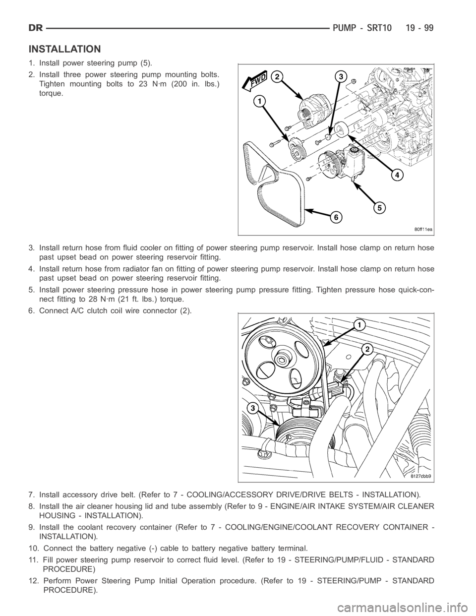
1. Install power steering pump (5).
2. Install three power steering pump mounting bolts.
Tighten mounting bolts to 23 Nꞏm (200 in. lbs.)
torque.
3. Install return hose from fluid cooler on fitting of power steering pump reservoir. Install hose clamp on return hose
past upset bead on power steering reservoir fitting.
4. Install return hose from radiator fan on fitting of power steering pump reservoir. Install hose clamp on return hose
past upset bead on power steering reservoir fitting.
5. Install power steering pressure hose in power steering pump pressure fitting. Tighten pressure hose quick-con-
nect fitting to 28 Nꞏm (21 ft. lbs.) torque.
6. Connect A/C clutch coil wire connector (2).
7. Install accessory drive belt. (Refer to 7 - COOLING/ACCESSORY DRIVE/DRIVE BELTS - INSTALLATION).
8. Install the air cleaner housing lid and tube assembly (Refer to 9 - ENGINE/AIR INTAKE SYSTEM/AIR CLEANER
HOUSING - INSTALLATION).
9. Install the coolant recovery container (Refer to 7 - COOLING/ENGINE/COOLANT RECOVERY CONTAINER -
INSTALLATION).
10. Connect the battery negative (-) cable to battery negative battery terminal.
11. Fill power steering pump reservoir to correct fluid level. (Refer to 19- STEERING/PUMP/FLUID - STANDARD
PROCEDURE)
12. Perform Power Steering Pump Initial Operation procedure. (Refer to 19- STEERING/PUMP - STANDARD
PROCEDURE).
Page 2513 of 5267

RETURN HOSE - GEAR TO COOLER
NOTE: Before installing power steering hose,
replace used O-rings as necessary. Clean hose
ends, fittings and open ports with a lint-free cloth.
Lubricate O-rings with clean power steering fluid.
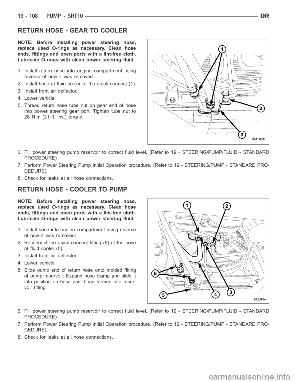
1. Install return hose into engine compartment using
reverse of how it was removed.
2. Install hose at fluid cooler to the quick connect (1).
3. Install front air deflector.
4. Lower vehicle.
5. Thread return hose tube nut on gear end of hose
into power steering gear port. Tighten tube nut to
28 Nꞏm (21 ft. lbs.) torque.
6. Fill power steering pump reservoir to correct fluid level. (Refer to 19 -STEERING/PUMP/FLUID - STANDARD
PROCEDURE)
7. Perform Power Steering Pump Initial Operation procedure. (Refer to 19 -STEERING/PUMP - STANDARD PRO-
CEDURE).
8. Check for leaks at all hose connections.
RETURN HOSE - COOLER TO PUMP
NOTE: Before installing power steering hose,
replace used O-rings as necessary. Clean hose
ends, fittings and open ports with a lint-free cloth.
Lubricate O-rings with clean power steering fluid.
1. Install hose into engine compartment using reverse
of how it was removed.
2. Reconnect the quick connect fitting (6) of the hose
at fluid cooler (5).
3. Install front air deflector.
4. Lower vehicle.
5. Slide pump end of return hose onto molded fitting
of pump reservoir. Expand hose clamp and slide it
into position on hose past bead formed into reser-
voir fitting.
6. Fill power steering pump reservoir to correct fluid level. (Refer to 19 -STEERING/PUMP/FLUID - STANDARD
PROCEDURE)
7. Perform Power Steering Pump Initial Operation procedure. (Refer to 19 -STEERING/PUMP - STANDARD PRO-
CEDURE).
8. Check for leaks at all hose connections.
Page 2515 of 5267
PULLEY
REMOVAL
1. Remove the power steering pump assembly (1),
(Refer to 19 - STEERING/PUMP - REMOVAL).
2. Remove the pulley (2) from the pump using (OTC
7185) power steering pulley removal tool or equiv-
alent (3).
INSTALLATION
1. Replace pulley (1) if bent, cracked, or loose.
2. Install pulley (1) on pump with Installer C-4063-B
(2) flush with the end of the shaft. Ensure the tool
and pulley remain aligned with the pump shaft.
3. Install pump assembly.
4. With Serpentine Belts; Run engine until warm (5
min.) and note any belt chirp. If chirp exists, move
pulley outward approximately 0.5 mm (0.020 in.). If
noise increases, press on 1.0 mm (0.040 in.).Be
careful that pulley does not contact mounting
bolts.
Page 2526 of 5267
9. Disconnect harness from clips on transmission
housing.
10. Remove transfer case linkage 4x4 equipped.
11. Remove transfer case mounting nuts and remove
transfer case 4x4 equipped.
12. Remove slave cylinder (1) mounting nuts (2) and
remove cylinder.
13. Remove starter motor (1) on 5.7L engine.
Page 2527 of 5267
14. Remove structural dust cover (1) clutch housing
bolts (2) and dust shield bolts (3) on 5.7L engine.
CAUTION: On 5.7L engine do not remove struc-
tural dust cover from engine block. If cover is
removed clutch housing and structural dust cover
must be aligned with the engine.
15. Remove exhaust bracket (1) bolts and remove
bracket on diesel engine.
Page 2528 of 5267
16. Support engine with adjustable jack stand and
wood block.
17. Support and secure transmission (1) to a trans-
mission jack (2) with safety chains.
18. Remove transmission mount bolts (1).
19. Remove rear crossmember bolts (2) and remove
crossmember with transmission mount.
20. Remove exhaust Y-pipe on 5.7L engine.
21. Remove bolts attaching transmission to the
engine.
22. Move transmission rearward until input shaft is
clear of clutch disc and pressure plate. Then
lower jack and remove transmission from under
vehicle.