2006 DODGE RAM SRT-10 engine
[x] Cancel search: enginePage 2755 of 5267

5.CHECK THE (T54) TRANSMISSION TEMPERATURE SENSOR SIGNAL CIRCUIT FOR A SHORTTO
V O LTA G E
Ignition on, engine not running.
With the scan tool under TIPM, actuate the Transmission.
Measure the voltage of the (T54) Transmission Temperature Sensor
Signal circuit in the appropriate terminal of Miller tool #8815.
Is the voltage above 0.5 volts?
Ye s>>
Repair the (T54) Transmission Temperature Sensor Signal
circuit for a short to voltage.
Perform 42RLE TRANSMISSION VERIFICATION TEST -
VER 1. (Refer to 21 - TRANSMISSION/TRANSAXLE/AU-
TOMATIC - 42RLE - STANDARD PROCEDURE)
No>>
Using the schematics as a guide, check the Powertrain
Control Module (PCM) terminals for corrosion, damage, or
terminal push out. Pay particular attention to all power and
ground circuits. Check for Service Information Tune-ups or
Service Bulletins for any possible causes that may apply. If
no problems are found, replace the PCM per the Service
Information. With the scan tool, perform QUICK LEARN.
Perform 42RLE TRANSMISSION VERIFICATION TEST - VER 1. (Refer to 21 - TRANSMISSION/
TRANSAXLE/AUTOMATIC - 42RLE - STANDARD PROCEDURE)
6.INTERMITTENT WIRING AND CONNECTORS
The conditions necessary to set this DTC are not present at this time.
Using the schematics as a guide, inspect the wiring and connectors specifictothiscircuit.
Wiggle the wires while checking for shorted and open circuits.
With the scan tool, check the DTC EVENT DATA to help identify the conditionsin which the DTC was set.
Check for any Service Information Tune-ups or Service Bulletins for any possible causes that may apply.
Were there any problems found?
Ye s>>
Repair as necessary.
Perform 42RLE TRANSMISSION VERIFICATION TEST - VER 1. (Refer to 21 - TRANSMISSION/
TRANSAXLE/AUTOMATIC - 42RLE - STANDARD PROCEDURE)
No>>
Te s t C o m p l e t e .
Page 2757 of 5267
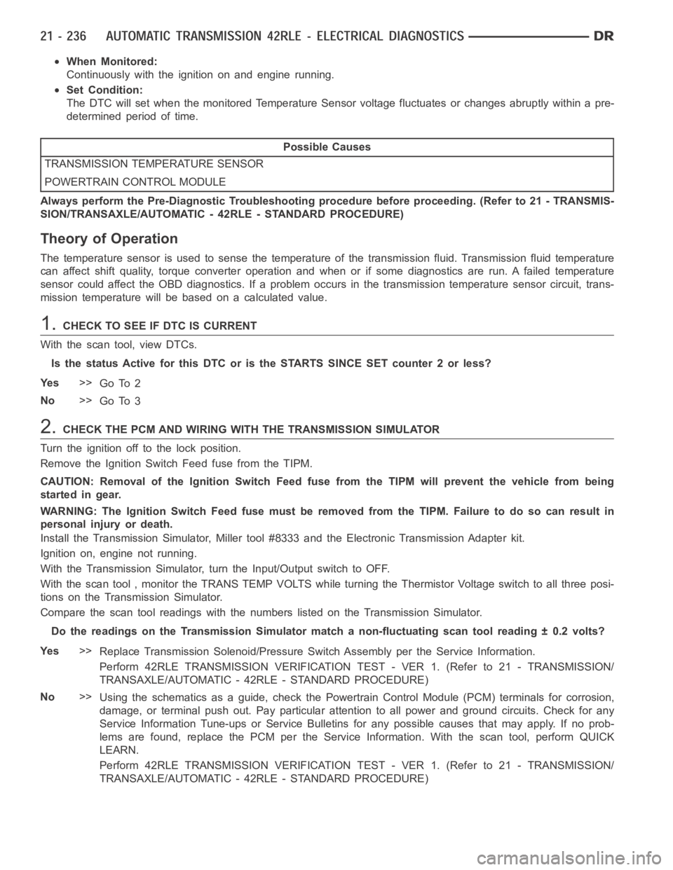
When Monitored:
Continuously with the ignition on and engine running.
Set Condition:
The DTC will set when the monitored Temperature Sensor voltage fluctuatesor changes abruptly within a pre-
determined period of time.
Possible Causes
TRANSMISSION TEMPERATURE SENSOR
POWERTRAIN CONTROL MODULE
Always perform the Pre-Diagnostic Troubleshooting procedure before proceeding. (Refer to 21 - TRANSMIS-
SION/TRANSAXLE/AUTOMATIC - 42RLE - STANDARD PROCEDURE)
Theory of Operation
The temperature sensor is used to sense the temperature of the transmission fluid. Transmission fluid temperature
can affect shift quality, torque converter operation and when or if some diagnostics are run. A failed temperature
sensor could affect the OBD diagnostics. If a problem occurs in the transmission temperature sensor circuit, trans-
mission temperature will be based on a calculated value.
1.CHECK TO SEE IF DTC IS CURRENT
With the scan tool, view DTCs.
Is the status Active for this DTC or is the STARTS SINCE SET counter 2 or less?
Ye s>>
Go To 2
No>>
Go To 3
2.CHECK THE PCM AND WIRING WITH THE TRANSMISSION SIMULATOR
Turn the ignition off to the lock position.
Remove the Ignition Switch Feed fuse from the TIPM.
CAUTION: Removal of the Ignition Switch Feed fuse from the TIPM will prevent the vehicle from being
startedingear.
WARNING: The Ignition Switch Feed fuse must be removed from the TIPM. Failure to do so can result in
personal injury or death.
Install the Transmission Simulator,Miller tool #8333 and the ElectronicTransmission Adapter kit.
Ignition on, engine not running.
With the Transmission Simulator, turn the Input/Output switch to OFF.
With the scan tool , monitor the TRANS TEMP VOLTS while turning the ThermistorVoltageswitchtoallthreeposi-
tions on the Transmission Simulator.
Compare the scan tool readings with the numbers listed on the TransmissionSimulator.
Do the readings on the Transmission Simulator match a non-fluctuating scan tool reading ± 0.2 volts?
Ye s>>
Replace Transmission Solenoid/Pressure Switch Assembly per the ServiceInformation.
Perform 42RLE TRANSMISSION VERIFICATION TEST - VER 1. (Refer to 21 - TRANSMISSION/
TRANSAXLE/AUTOMATIC - 42RLE - STANDARD PROCEDURE)
No>>
Using the schematics as a guide, check the Powertrain Control Module (PCM)terminals for corrosion,
damage, or terminal push out. Pay particular attention to all power and ground circuits. Check for any
Service Information Tune-ups or Service Bulletins for any possible causes that may apply. If no prob-
lems are found, replace the PCM per the Service Information. With the scan tool, perform QUICK
LEARN.
Perform 42RLE TRANSMISSION VERIFICATION TEST - VER 1. (Refer to 21 - TRANSMISSION/
TRANSAXLE/AUTOMATIC - 42RLE - STANDARD PROCEDURE)
Page 2760 of 5267
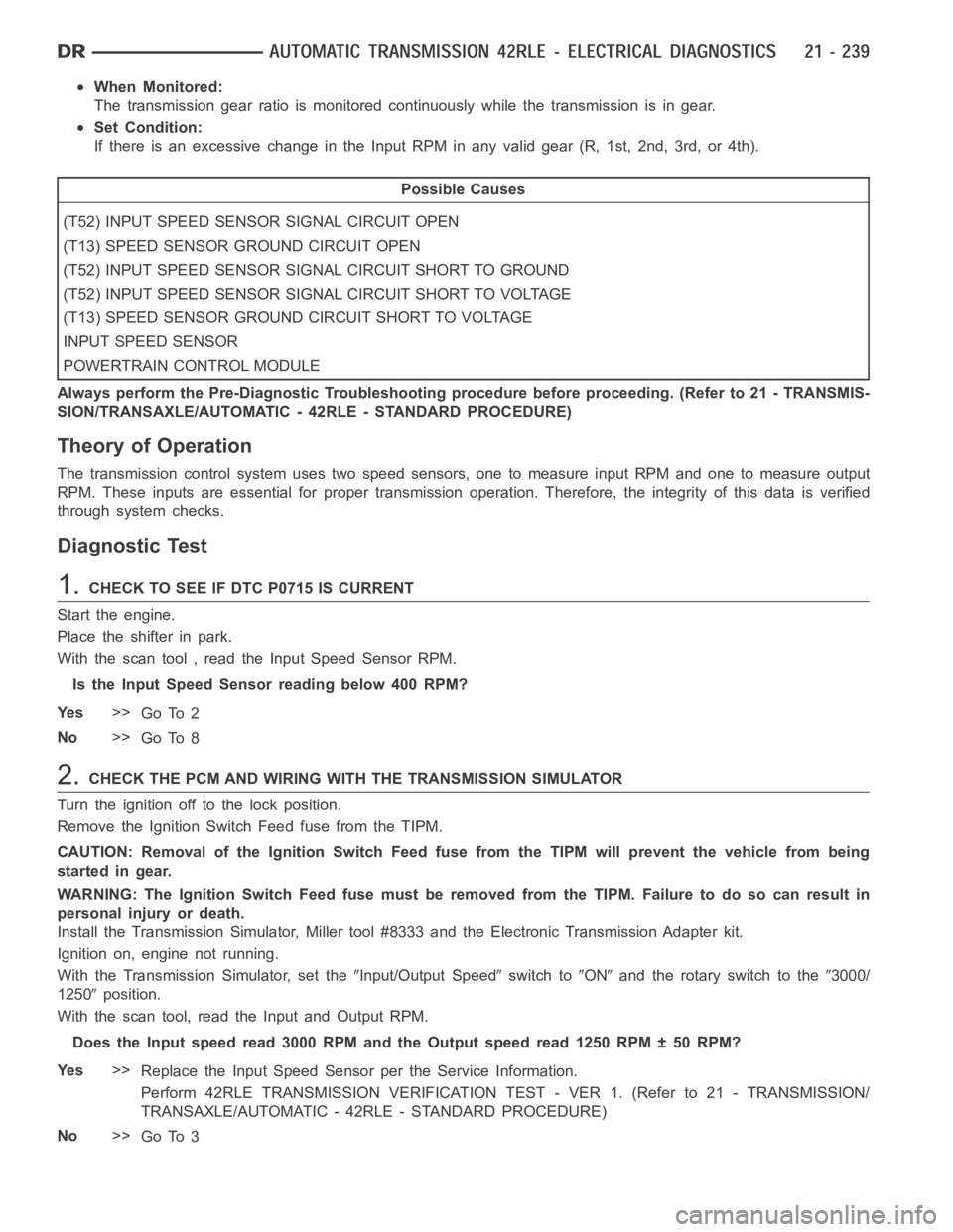
When Monitored:
The transmission gear ratio is monitored continuously while the transmission is in gear.
Set Condition:
If there is an excessive change in the Input RPM in any valid gear (R, 1st, 2nd, 3rd, or 4th).
Possible Causes
(T52) INPUT SPEED SENSOR SIGNAL CIRCUIT OPEN
(T13) SPEED SENSOR GROUND CIRCUIT OPEN
(T52) INPUT SPEED SENSOR SIGNAL CIRCUIT SHORT TO GROUND
(T52) INPUT SPEED SENSOR SIGNAL CIRCUIT SHORT TO VOLTAGE
(T13) SPEED SENSOR GROUND CIRCUIT SHORT TO VOLTAGE
INPUT SPEED SENSOR
POWERTRAIN CONTROL MODULE
Always perform the Pre-Diagnostic Troubleshooting procedure before proceeding. (Refer to 21 - TRANSMIS-
SION/TRANSAXLE/AUTOMATIC - 42RLE - STANDARD PROCEDURE)
Theory of Operation
The transmission control system usestwo speed sensors, one to measure input RPM and one to measure output
RPM. These inputs are essential for proper transmission operation. Therefore, the integrity of this data is verified
through system checks.
Diagnostic Test
1.CHECK TO SEE IF DTC P0715 IS CURRENT
Start the engine.
Place the shifter in park.
With the scan tool , read the Input Speed Sensor RPM.
Is the Input Speed Sensor reading below 400 RPM?
Ye s>>
Go To 2
No>>
Go To 8
2.CHECK THE PCM AND WIRING WITH THE TRANSMISSION SIMULATOR
Turn the ignition off to the lock position.
Remove the Ignition Switch Feed fuse from the TIPM.
CAUTION: Removal of the Ignition Switch Feed fuse from the TIPM will prevent the vehicle from being
startedingear.
WARNING: The Ignition Switch Feed fuse must be removed from the TIPM. Failure to do so can result in
personal injury or death.
Install the Transmission Simulator,Miller tool #8333 and the ElectronicTransmission Adapter kit.
Ignition on, engine not running.
With the Transmission Simulator, set the
Input/Output Speedswitch toONand the rotary switch to the3000/
1250
position.
With the scan tool, read the Input and Output RPM.
Does the Input speed read 3000 RPM and the Output speed read 1250 RPM ± 50 RPM?
Ye s>>
Replace the Input Speed Sensor per the Service Information.
Perform 42RLE TRANSMISSION VERIFICATION TEST - VER 1. (Refer to 21 - TRANSMISSION/
TRANSAXLE/AUTOMATIC - 42RLE - STANDARD PROCEDURE)
No>>
Go To 3
Page 2762 of 5267

5.CHECK THE (T52) INPUT SPEED SENSOR SIGNAL CIRCUIT FOR A SHORT TO GROUND
Measure the resistance between ground and the (T52) Input Speed
Sensor Signal circuit.
Is the resistance Below 5.0 ohms?
Ye s>>
Repair the (T52) Input Speed Sensor Signal circuit for a
short to ground.
Perform 42RLE TRANSMISSION VERIFICATION TEST -
VER 1. (Refer to 21 - TRANSMISSION/TRANSAXLE/AU-
TOMATIC - 42RLE - STANDARD PROCEDURE)
No>>
Go To 6
6.CHECK THE (T52) INPUT SPEED SENSOR SIGNAL CIRCUIT FOR A SHORT TO VOLTAGE
Disconnect the Output Speed Sensor harness connector.
Ignition on, engine not running.
With the scan tool under TIPM, actuate the Transmission.
Measure the voltage of the (T52) Input Speed Sensor Signal circuit.
Is the voltage above 0.5 volt?
Ye s>>
Repair the (T52) Input Speed Sensor Signal circuit for a
short to voltage.
Perform 42RLE TRANSMISSION VERIFICATION TEST -
VER 1. (Refer to 21 - TRANSMISSION/TRANSAXLE/AU-
TOMATIC - 42RLE - STANDARD PROCEDURE)
No>>
Go To 7
Page 2765 of 5267
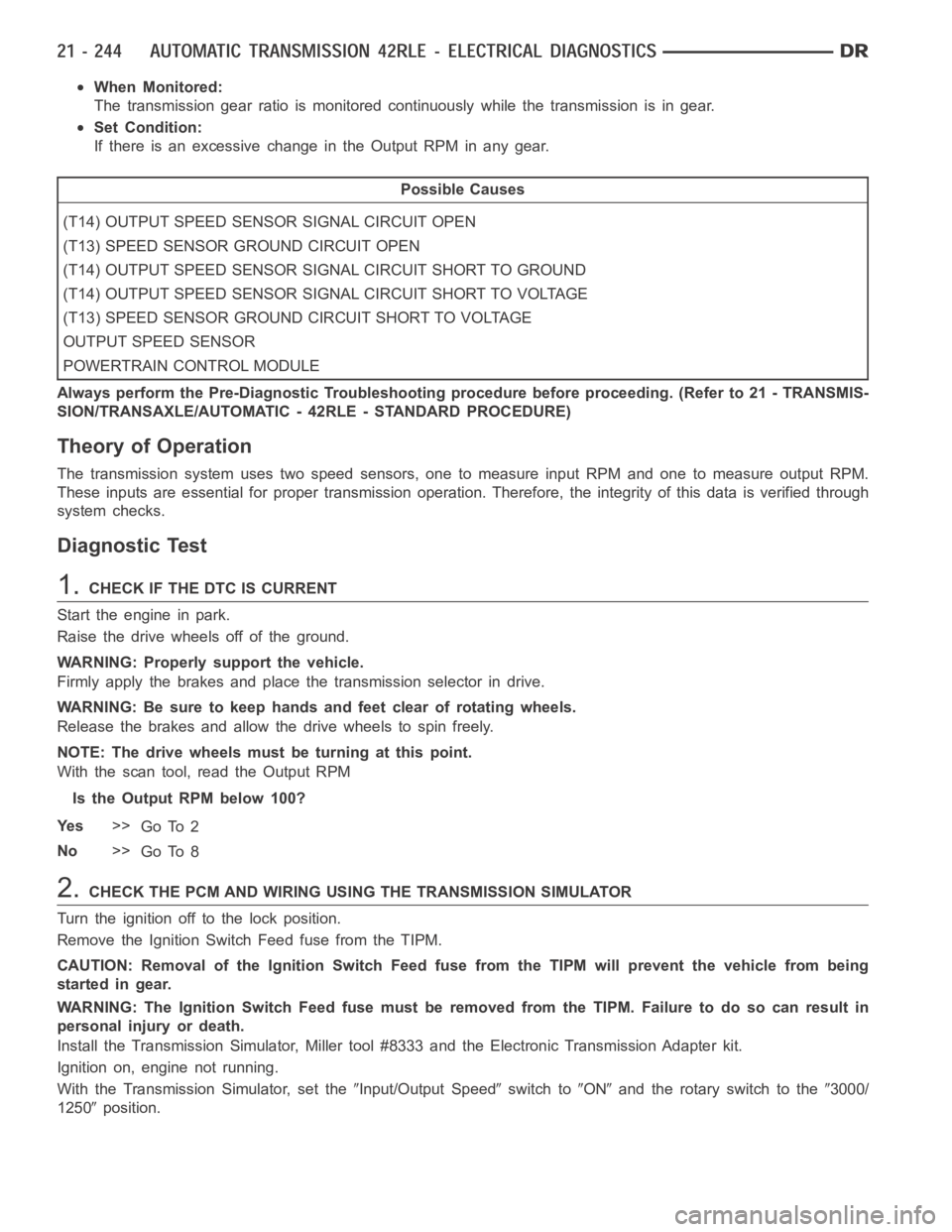
When Monitored:
The transmission gear ratio is monitored continuously while the transmission is in gear.
Set Condition:
If there is an excessive change in the Output RPM in any gear.
Possible Causes
(T14) OUTPUT SPEED SENSOR SIGNAL CIRCUIT OPEN
(T13) SPEED SENSOR GROUND CIRCUIT OPEN
(T14) OUTPUT SPEED SENSOR SIGNAL CIRCUIT SHORT TO GROUND
(T14) OUTPUT SPEED SENSOR SIGNAL CIRCUIT SHORT TO VOLTAGE
(T13) SPEED SENSOR GROUND CIRCUIT SHORT TO VOLTAGE
OUTPUT SPEED SENSOR
POWERTRAIN CONTROL MODULE
Always perform the Pre-Diagnostic Troubleshooting procedure before proceeding. (Refer to 21 - TRANSMIS-
SION/TRANSAXLE/AUTOMATIC - 42RLE - STANDARD PROCEDURE)
Theory of Operation
The transmission system uses two speed sensors, one to measure input RPM and one to measure output RPM.
These inputs are essential for proper transmission operation. Therefore, the integrity of this data is verified through
system checks.
Diagnostic Test
1.CHECK IF THE DTC IS CURRENT
Start the engine in park.
Raise the drive wheels off of the ground.
WARNING: Properly support the vehicle.
Firmly apply the brakes and place the transmission selector in drive.
WARNING: Be sure to keep hands and feet clear of rotating wheels.
Release the brakes and allow the drive wheels to spin freely.
NOTE: The drive wheels must be turning at this point.
With the scan tool, read the Output RPM
Is the Output RPM below 100?
Ye s>>
Go To 2
No>>
Go To 8
2.CHECK THE PCM AND WIRING USING THE TRANSMISSION SIMULATOR
Turn the ignition off to the lock position.
Remove the Ignition Switch Feed fuse from the TIPM.
CAUTION: Removal of the Ignition Switch Feed fuse from the TIPM will prevent the vehicle from being
startedingear.
WARNING: The Ignition Switch Feed fuse must be removed from the TIPM. Failure to do so can result in
personal injury or death.
Install the Transmission Simulator,Miller tool #8333 and the ElectronicTransmission Adapter kit.
Ignition on, engine not running.
With the Transmission Simulator, set the
Input/Output Speedswitch toONand the rotary switch to the3000/
1250
position.
Page 2768 of 5267
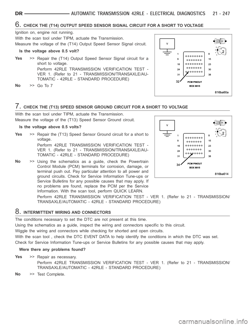
6.CHECK THE (T14) OUTPUT SPEED SENSOR SIGNAL CIRCUIT FOR A SHORT TO VOLTAGE
Ignition on, engine not running.
With the scan tool under TIPM, actuate the Transmission.
Measure the voltage of the (T14) Output Speed Sensor Signal circuit.
Is the voltage above 0.5 volt?
Ye s>>
Repair the (T14) Output Speed Sensor Signal circuit for a
short to voltage.
Perform 42RLE TRANSMISSION VERIFICATION TEST -
VER 1. (Refer to 21 - TRANSMISSION/TRANSAXLE/AU-
TOMATIC - 42RLE - STANDARD PROCEDURE)
No>>
Go To 7
7.CHECK THE (T13) SPEED SENSOR GROUND CIRCUIT FOR A SHORT TO VOLTAGE
With the scan tool under TIPM, actuate the Transmission.
Measure the voltage of the (T13) Speed Sensor Ground circuit.
Is the voltage above 0.5 volts?
Ye s>>
Repair the (T13) Speed Sensor Ground circuit for a short to
voltage.
Perform 42RLE TRANSMISSION VERIFICATION TEST -
VER 1. (Refer to 21 - TRANSMISSION/TRANSAXLE/AU-
TOMATIC - 42RLE - STANDARD PROCEDURE)
No>>
Using the schematics as a guide, check the Powertrain
Control Module (PCM) terminals for corrosion, damage, or
terminal push out. Pay particular attention to all power and
ground circuits. Check for Service Information Tune-ups or
Service Bulletins for any possible causes that may apply. If
no problems are found, replace the PCM per the Service
Information. With the scan tool, perform QUICK LEARN.
Perform 42RLE TRANSMISSION VERIFICATION TEST - VER 1. (Refer to 21 - TRANSMISSION/
TRANSAXLE/AUTOMATIC - 42RLE - STANDARD PROCEDURE)
8.INTERMITTENT WIRING AND CONNECTORS
The conditions necessary to set the DTC are not present at this time.
Using the schematics as a guide, inspect the wiring and connectors specifictothiscircuit.
Wiggle the wiring and connectors while checking for shorted and open circuits.
With the scan tool , check the DTC EVENT DATA to help identify the conditionsin which the DTC was set.
Check for Service Information Tune-ups or Service Bulletins for any possible causes that may apply.
Were there any problems found?
Ye s>>
Repair as necessary.
Perform 42RLE TRANSMISSION VERIFICATION TEST - VER 1. (Refer to 21 - TRANSMISSION/
TRANSAXLE/AUTOMATIC - 42RLE - STANDARD PROCEDURE)
No>>
Te s t C o m p l e t e .
Page 2769 of 5267

P0725-ENGINE SPEED SENSOR CIRCUIT
For a complete wiring diagramRefer to Section 8W.
When Monitored:
Whenever the engine is running.
Set Condition:
The Engine RPM is less than 390 or greater than 8000 for more than 2 seconds while the engine is running.
Possible Causes
ENGINE DTCS PRESENT
POWERTRAIN CONTROL MODULE
Always perform the Pre-Diagnostic Troubleshooting procedure before proceeding. (Refer to 21 - TRANSMIS-
SION/TRANSAXLE/AUTOMATIC - 42RLE - STANDARD PROCEDURE)
Theory of Operation
The PCM uses a dual port RAM internal to the controller to send the engine speed signal to the Transmission
Control System. The calculated engine RPM is compared to a minimum and maximum value. If the PCM interprets
this signal to be out of range when the engine is running the code is set. The MIL illuminates after 10 seconds of
vehicle operation and the transmission system defaults to Limp-in mode.
Diagnostic Test
1.CHECK IF THE DTC IS CURRENT
Start the engine.
NOTE: This DTC is not a Transmission Input Speed Sensor DTC.
With the scan tool, read transmission DTCs.
Is the status Active for this DTC or is the STARTS SINCE SET counter set at 0?
Ye s>>
Go To 2
No>>
Go To 3
2.CHECK IF ENGINE DTCS ARE PRESENT
With the scan tool, read engine DTCs.
Are there any engine DTC’s present?
Ye s>>
Refer to Section 9 – Engine Electrical Diagnostics and perform the appropriate diagnostic procedure.
Perform 42RLE TRANSMISSION VERIFICATION TEST - VER 1. (Refer to 21 - TRANSMISSION/
TRANSAXLE/AUTOMATIC - 42RLE - STANDARD PROCEDURE)
No>>
Using the schematics as a guide, check the Powertrain Control Module (PCM)terminals for corrosion,
damage, or terminal push out. Pay particular attention to all power and ground circuits. Check for Ser-
vice Information Tune-ups or Service Bulletins for any possible causes that may apply. If no problems
are found, replace the PCM per the Service Information. With the scan tool,perform QUICK LEARN.
Perform 42RLE TRANSMISSION VERIFICATION TEST - VER 1. (Refer to 21 - TRANSMISSION/
TRANSAXLE/AUTOMATIC - 42RLE - STANDARD PROCEDURE)
Page 2781 of 5267
P0740-TCC OUT OF RANGE
For a complete wiring diagramRefer to Section 8W.
When Monitored:
The Torque Converter Clutch (TCC) is in FEMCC or PEMCC, Transmission temperature is hot, Engine tem-
perature is greater than 38° C or 100° F, Transmission Input Speed greater than engine speed, TPS less than
30°, and brake not applied.
Set Condition:
The TCC is modulated by controlling the duty cycle of the L/R Solenoid untilthe difference between the Engine
RPM and the Transmission Input Speed RPM or duty cycle is within a desired range. The DTC is set after the
period of 10 seconds and 3 occurrences of either: FEMCC - with slip greater than 100 RPM or PEMCC - duty
cycle greater than 85%.
Possible Causes
RELATED L/R SOLENOID OR PRESSURE SWITCH DTCS PRESENT
INTERNAL TRANSMISSION
Always perform the Pre-Diagnostic Troubleshooting procedure before proceeding. (Refer to 21 - TRANSMIS-
SION/TRANSAXLE/AUTOMATIC - 42RLE - STANDARD PROCEDURE)
Theory of Operation
When in 2nd, 3rd, or 4th gear, the torque converter clutch (TCC) can be locked or partially locked when certain
conditions are met. The TCC piston is electronically modulated by increasing the duty cycle of the LR/TCC solenoid
until the torque converter slip difference (difference between engine and turbine speed) is within 60 RPM. Then the
LR/TCC solenoid is fully energized (FEMCC / 100% duty cycle). Torque converter slip is monitored in FEMCC to
ensure adequate clutch capacity. The transmission will attempt normal EMCC operation (not in Limp-in) even after
the MIL is illuminated. MIL will illuminate after 5 minutes of accumulatedslip in FEMCC.
Diagnostic Test
1.CHECK IF RELATED DTCS ARE PRESENT
With the scan tool, read Transmission DTCs
Are the DTCs P0750 and/or P0841 present also?
Ye s>>
Refer to the Transmission category and perform the appropriate symptom.
No>>
Go To 2
2.CHECK IF THE DTC IS CURRENT
Ignition on, engine not running.
With the scan tool, record and erase DTCs.
Drive the vehicle until it is fully warmed up to at least 43° C (110° F).
Perform the following step 3 times.
Drive the vehicle at 50 mph and allow 4th gear to engage for at least 10 seconds. Close the throttle, then tip back
in until the throttle angle is between 25 and 29 degrees. Note that if you go over 30 degrees, you must back off of
the throttle and retry.
Did the TCC engage during any of the attempts?
Ye s>>
Go To 3
No>>
Perform the Hydraulic Pressure test per the Service Information and repair the internal transmission
components and Torque convertor as necessary.
Perform 42RLE TRANSMISSION VERIFICATION TEST - VER 1. (Refer to 21 - TRANSMISSION/
TRANSAXLE/AUTOMATIC - 42RLE - STANDARD PROCEDURE)