Page 4440 of 5267
SIDE VIEW MIRROR
REMOVAL
1. Remove the door trim panel (Refer to 23 - BODY/
DOOR - FRONT/TRIM PANEL - REMOVAL).
2. Disconnect the wire harness connector (3) from the
mirror (1).
3. Remove the three nuts (2) that secure the mirror to
the door and carefully remove the mirror.
INSTALLATION
1. Position the mirror (1) onto the door.
2. Install the three nuts (2) that secure the mirror to
the door. Tighten the nuts to 7 Nꞏm (60 in. lbs.).
3. Connect the wire harness connector (3) to the mir-
ror.
4. Install the door trim panel (Refer to 23 - BODY/
DOOR - FRONT/TRIM PANEL - INSTALLATION).
Page 4441 of 5267
SIDE VIEW MIRROR GLASS
REMOVAL
STANDARD MIRROR
WARNING: Always wear eye and hand protection
when servicing the mirror assembly. Failure to
observe this warning may result in personal injury
from broken glass.
1. Position the glass (3) in the mirror (2) as shown to
access the two outboard mirror housing retainer
clips (1).
2. Disengage the three mirror housing retainer clips
(2) (start with the two outboard clips) and remove
the cover.
3. Disengage the lower glass retainer clip (2) from the
mirror motor.
4. Slide the mirror glass (1) upward from the mirror
motor and remove the glass from the motor.
NOTE: When disconnecting the wire harness con-
nectors from the heated mirror glass terminals,
note the location of each connector and its
respective terminal for installation reference.
5. If equipped with heated mirrors, disconnect the
wire harness connectors from the mirror glass.
Page 4442 of 5267
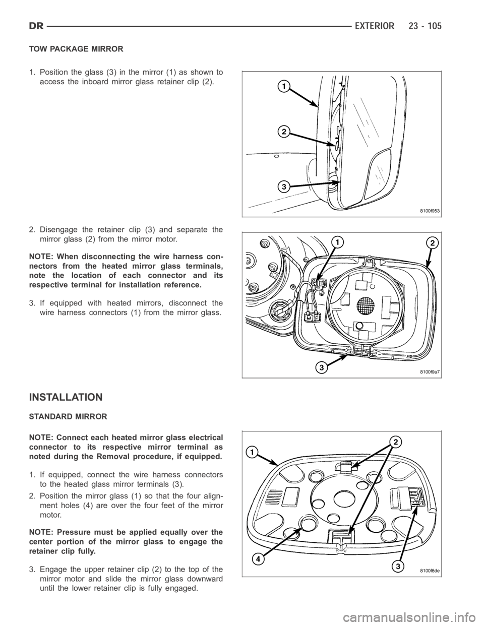
TOW PACKAGE MIRROR
1. Position the glass (3) in the mirror (1) as shown to
access the inboard mirror glass retainer clip (2).
2. Disengage the retainer clip (3) and separate the
mirror glass (2) from the mirror motor.
NOTE: When disconnecting the wire harness con-
nectors from the heated mirror glass terminals,
note the location of each connector and its
respective terminal for installation reference.
3. If equipped with heated mirrors, disconnect the
wire harness connectors (1) from the mirror glass.
INSTALLATION
STANDARD MIRROR
NOTE: Connect each heated mirror glass electrical
connector to its respective mirror terminal as
noted during the Removal procedure, if equipped.
1. If equipped, connect the wire harness connectors
to the heated glass mirror terminals (3).
2. Position the mirror glass (1) so that the four align-
ment holes (4) are over the four feet of the mirror
motor.
NOTE: Pressure must be applied equally over the
center portion of the mirror glass to engage the
retainer clip fully.
3. Engage the upper retainer clip (2) to the top of the
mirror motor and slide the mirror glass downward
until the lower retainerclip is fully engaged.
Page 4443 of 5267
4. Position the mirror housing (1) onto the mirror and
fully engage the three retainer clips (2).
TOW PACKAGE MIRROR
NOTE: Connect each heated mirror glass electrical
connector to its respective mirror terminal as
noted during the Removal procedure, if equipped.
1. If equipped, connect the wire harness connectors
to the heated glass mirror terminals (1).
NOTE: Pressure must be applied equally over the
center portion of the mirror glass to engage the
retainer clip fully.
2. Install the mirror glass (2) onto the mirror motor
and fully engage the retainer clip (3).
Page 4513 of 5267
page page
INTERIOR
CAUTION ................................... 177
4WD FLOOR SHIFT BOOT
REMOVAL ................................... 178
INSTALLATION .............................. 178
A-PILLAR TRIM/GRAB HANDLE
REMOVAL ................................... 180
INSTALLATION .............................. 180
B-PILLAR GRAB HANDLE
REMOVAL ................................... 181
INSTALLATION .............................. 181
B-PILLAR LOWER TRIM
REMOVAL ................................... 182
INSTALLATION .............................. 183
B-PILLAR UPPER TRIM
REMOVAL ................................... 184
INSTALLATION .............................. 185
C-PILLAR LOWER TRIM
REMOVAL ................................... 187
INSTALLATION .............................. 187
C-PILLAR UPPER TRIM
REMOVAL ................................... 188
INSTALLATION .............................. 188
CARPETS AND FLOOR MATS
REMOVAL ................................... 189
INSTALLATION .............................. 191
COAT HOOK
REMOVAL ................................... 194
INSTALLATION .............................. 194
COWL TRIM
REMOVAL ................................... 195INSTALLATION .............................. 195
FLOOR CONSOLE
REMOVAL ................................... 196
INSTALLATION .............................. 199
HEADLINER
REMOVAL ................................... 202
INSTALLATION .............................. 202
LOAD FLOOR
REMOVAL ................................... 204
INSTALLATION .............................. 205
REAR CAB BACK PANEL TRIM
REMOVAL ................................... 206
INSTALLATION .............................. 207
REAR DOOR SILL TRIM COVER
REMOVAL ................................... 209
INSTALLATION .............................. 209
REAR VIEW MIRROR
REMOVAL ................................... 210
INSTALLATION
INSTALLATION ............................ 210
REAR VIEW MIRROR MOUNTING BRACKET . 210
SUN VISOR
REMOVAL ................................... 212
INSTALLATION .............................. 212
SUN VISOR SUPPORT
REMOVAL ................................... 213
INSTALLATION .............................. 213
BODY VENT
REMOVAL ................................... 214
INSTALLATION .............................. 214
Page 4539 of 5267
HEADLINER
REMOVAL
NOTE: Headliner for Quad Cab model shown. Reg-
ular cab similar.
1. Remove the A-pillar trim panels (Refer to 23 -
BODY/INTERIOR/A-PILLAR TRIM - REMOVAL).
2. Remove the upper B-pillar trim panels (Refer to 23
- BODY/INTERIOR/B-PILLAR UPPER TRIM -
REMOVAL).
3. On Quad Cab models, remove the upper C-pillar
trim panels (Refer to 23 - BODY/INTERIOR/C-PIL-
LAR TRIM - REMOVAL).
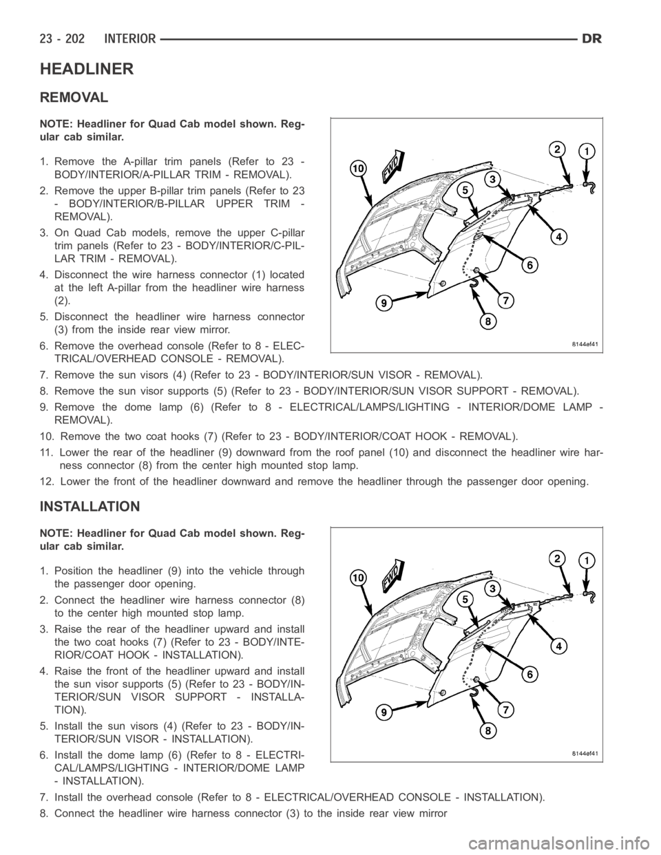
4. Disconnect the wire harness connector (1) located
at the left A-pillar from the headliner wire harness
(2).
5. Disconnect the headliner wire harness connector
(3) from the inside rear view mirror.
6. Remove the overhead console (Refer to 8 - ELEC-
TRICAL/OVERHEAD CONSOLE - REMOVAL).
7. Remove the sun visors (4) (Refer to 23 - BODY/INTERIOR/SUN VISOR - REMOVAL).
8. Remove the sun visor supports (5) (Refer to 23 - BODY/INTERIOR/SUN VISORSUPPORT - REMOVAL).
9. Remove the dome lamp (6) (Refer to 8 -ELECTRICAL/LAMPS/LIGHTING - INTERIOR/DOME LAMP -
REMOVAL).
10. Remove the two coat hooks (7) (Refer to 23 - BODY/INTERIOR/COAT HOOK - REMOVAL).
11. Lower the rear of the headliner (9) downward from the roof panel (10) anddisconnect the headliner wire har-
ness connector (8) from the center high mounted stop lamp.
12. Lower the front of the headliner downward and remove the headliner through the passenger door opening.
INSTALLATION
NOTE: Headliner for Quad Cab model shown. Reg-
ular cab similar.
1. Position the headliner (9) into the vehicle through
the passenger door opening.
2. Connect the headliner wire harness connector (8)
to the center high mounted stop lamp.
3. Raise the rear of the headliner upward and install
the two coat hooks (7) (Refer to 23 - BODY/INTE-
RIOR/COAT HOOK - INSTALLATION).
4. Raise the front of the headliner upward and install
the sun visor supports (5) (Refer to 23 - BODY/IN-
TERIOR/SUN VISOR SUPPORT - INSTALLA-
TION).
5. Install the sun visors (4) (Refer to 23 - BODY/IN-
TERIOR/SUN VISOR - INSTALLATION).
6. Install the dome lamp (6) (Refer to 8 - ELECTRI-
CAL/LAMPS/LIGHTING - INTERIOR/DOME LAMP
- INSTALLATION).
7. Install the overhead console (Refer to 8 - ELECTRICAL/OVERHEAD CONSOLE-INSTALLATION).
8. Connect the headliner wire harness connector (3) to the inside rear viewmirror
Page 4547 of 5267
REAR VIEW MIRROR
REMOVAL
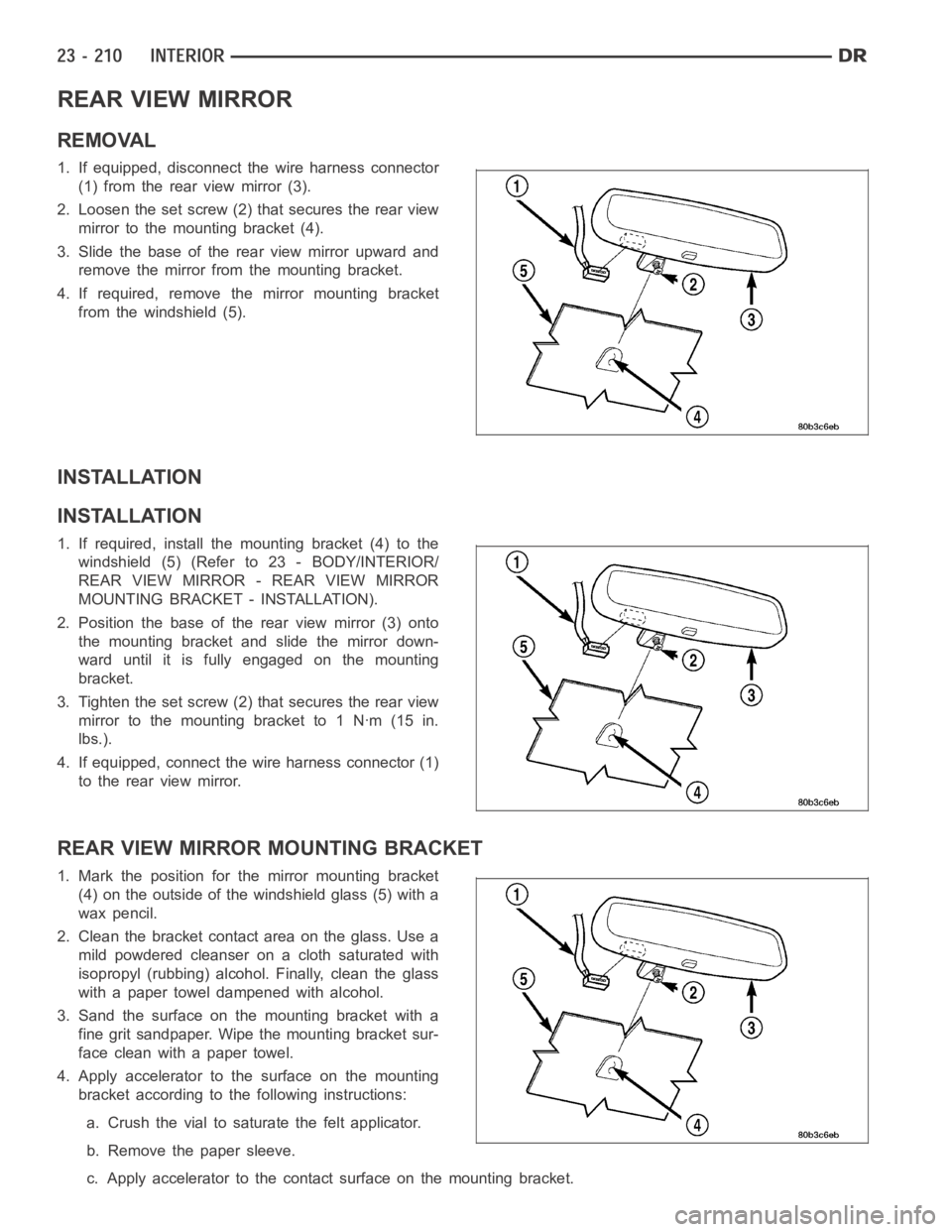
1. If equipped, disconnect the wire harness connector
(1) from the rear view mirror (3).
2. Loosen the set screw (2) that secures the rear view
mirror to the mounting bracket (4).
3. Slide the base of the rear view mirror upward and
remove the mirror from the mounting bracket.
4. If required, remove the mirror mounting bracket
from the windshield (5).
INSTALLATION
INSTALLATION
1. If required, install the mounting bracket (4) to the
windshield (5) (Refer to 23 - BODY/INTERIOR/
REAR VIEW MIRROR - REAR VIEW MIRROR
MOUNTING BRACKET - INSTALLATION).
2. Position the base of the rear view mirror (3) onto
the mounting bracket and slide the mirror down-
ward until it is fully engaged on the mounting
bracket.
3. Tighten the set screw (2) that secures the rear view
mirrortothemountingbracketto1Nꞏm(15in.
lbs.).
4. If equipped, connect the wire harness connector (1)
to the rear view mirror.
REAR VIEW MIRROR MOUNTING BRACKET
1.Markthepositionforthemirrormountingbracket
(4) on the outside of the windshield glass (5) with a
wax pencil.
2. Clean the bracket contact area on the glass. Use a
mild powdered cleanser on a cloth saturated with
isopropyl (rubbing) alcohol. Finally, clean the glass
with a paper towel dampened with alcohol.
3. Sand the surface on the mounting bracket with a
fine grit sandpaper. Wipe the mounting bracket sur-
face clean with a paper towel.
4. Apply accelerator to the surface on the mounting
bracket according to the following instructions:
a. Crush the vial to saturate the felt applicator.
b. Remove the paper sleeve.
c. Apply accelerator to the contact surface on the mounting bracket.
Page 4548 of 5267
d. Allow the accelerator to dry for five minutes.
e. Do not touch the bracket contact surface after the accelerator has been applied.
5. Apply adhesive accelerator to the bracket contact surface on the windshield glass. Allow the accelerator to dry
for one minute. Do not touch the glass contact surface after the accelerator has been applied.
6. Install the mounting bracket according to the following instructions:
a. Apply one drop of adhesive at the center of the bracket contact-surface on the windshield glass.
b. Apply an even coat of adhesive to the contact surface on the mounting bracket.
c. Align the mounting bracket with the marked position on the windshield glass.
d. Press and hold the mounting bracket in place for at least one minute.
NOTE: Verify that the mirror mounting bracket is correctly aligned, because the adhesive will cure rapidly.
7. Allow the adhesive to cure for 8-10 minutes. Remove any excess adhesive with an alcohol-dampened cloth.
8. Allow the adhesive to cure for an additional 8-10 minutes before installing the rear view mirror (3) (Refer to 23
- BODY/INTERIOR/REAR VIEW MIRROR - INSTALLATION).