2006 DODGE RAM SRT-10 mirror
[x] Cancel search: mirrorPage 203 of 5267
3.THROTTLE POSITION WITHIN 2° DEGREES OF DESIRED THROTTLE POSITION
Start the engine.
Allow the engine to reach normal operating temperature.
With a scan tool, monitor the Actual Throttle Position and Desired Throttle Position.
Compare the Actual Throttle Position and the Set Point Throttle Position.
Is the Actual Throttle Position within 2° degrees of the Desired Throttle Position?
Ye s>>
Go To 4
No>>
Replace the Throttle Body Assembly. Disconnect the Battery when replacing the Throttle Body Assem-
bly. After installation is complete, use a scan tool and select the ETC RELEARN function.
Perform the POWERTRAIN VERIFICATION TEST. (Refer to 9 - ENGINE - STANDARD PROCEDURE)
4.ETC OPERATION
Ignition on, engine not running.
With a scan tool, actuate the Electronic Throttle Control Motor.
NOTE: It may be necessary to use a mirror to see the throttle blade.
Observe the throttle blade.
NOTE: Make sure the motion of the throttle blade is smooth and that it opens and closes.
Did the ETC motor operate properly?
Ye s>>
Refer to the INTERMITTENT CONDITION Diagnostic Procedure.
Perform the POWERTRAIN VERIFICATION TEST. (Refer to 9 - ENGINE - STANDARD PROCEDURE)
No>>
Replace the Throttle Body Assembly. Disconnect the Battery when replacing the Throttle Body Assem-
bly. After installation is complete, use a scan tool and select the ETC RELEARN function.
Perform the POWERTRAIN VERIFICATION TEST. (Refer to 9 - ENGINE - STANDARD PROCEDURE)
Page 1608 of 5267
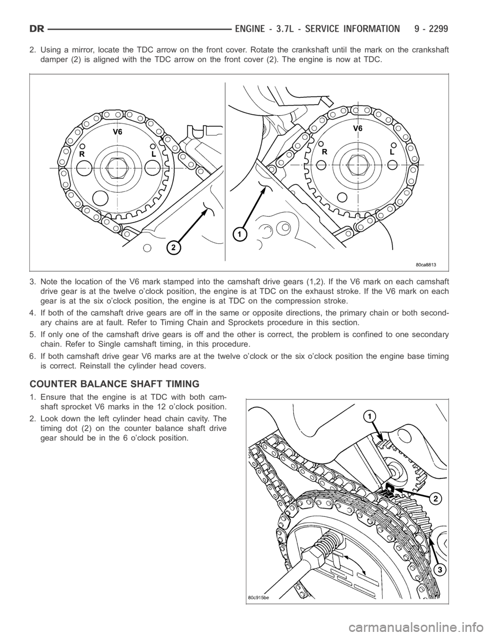
2. Using a mirror, locate the TDC arrow on the front cover. Rotate the crankshaft until the mark on the crankshaft
damper (2) is aligned with the TDC arrow on the front cover (2). The engine isnow at TDC.
3. Note the location of the V6 mark stamped into the camshaft drive gears (1,2). If the V6 mark on each camshaft
drive gear is at the twelve o’clock position, the engine is at TDC on the exhaust stroke. If the V6 mark on each
gear is at the six o’clock position, the engine is at TDC on the compression stroke.
4. If both of the camshaft drive gears are off in the same or opposite directions, the primary chain or both second-
ary chains are at fault. Refer to Timing Chain and Sprockets procedure in this section.
5. If only one of the camshaft drive gears is off and the other is correct, theproblem is confined to one secondary
chain. Refer to Single camshaft timing, in this procedure.
6. If both camshaft drive gear V6 marks are at the twelve o’clock or the six o’clock position the engine base timing
is correct. Reinstall the cylinder head covers.
COUNTER BALANCE SHAFT TIMING
1. Ensure that the engine is at TDC with both cam-
shaft sprocket V6 marks in the 12 o’clock position.
2. Look down the left cylinder head chain cavity. The
timing dot (2) on the counter balance shaft drive
gear should be in the 6 o’clock position.
Page 1741 of 5267
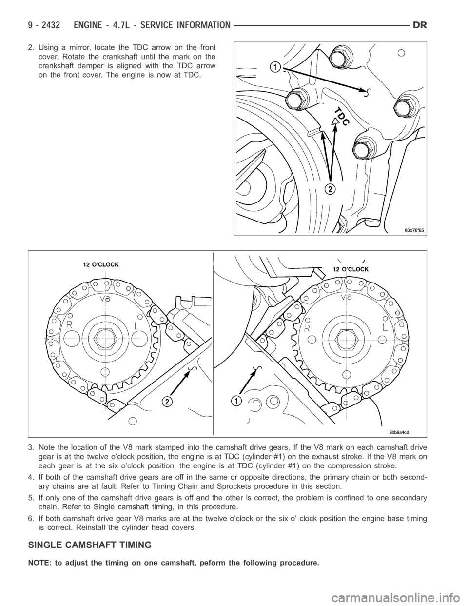
2. Using a mirror, locate the TDC arrow on the front
cover. Rotate the crankshaft until the mark on the
crankshaft damper is aligned with the TDC arrow
on the front cover. The engine is now at TDC.
3. Note the location of the V8 mark stamped into the camshaft drive gears. IftheV8markoneachcamshaftdrive
gear is at the twelve o’clock position, the engine is at TDC (cylinder #1) onthe exhaust stroke. If the V8 mark on
each gear is at the six o’clock position, the engine is at TDC (cylinder #1) on the compression stroke.
4. If both of the camshaft drive gears are off in the same or opposite directions, the primary chain or both second-
ary chains are at fault. Refer to Timing Chain and Sprockets procedure in this section.
5. If only one of the camshaft drive gears is off and the other is correct, theproblem is confined to one secondary
chain. Refer to Single camshaft timing, in this procedure.
6. If both camshaft drive gear V8 marks are at the twelve o’clock or the six o’clock position the engine base timing
is correct. Reinstall the cylinder head covers.
SINGLE CAMSHAFT TIMING
NOTE: to adjust the timing on one camshaft, peform the following procedure.
Page 4340 of 5267
vehicle. If the leak occurs on left turns, hoist the left side of the vehicle. If the leak occurs on right turns, hoist
the right side of the vehicle. For hoisting recommendations (Refer to LUBRICATION & MAINTENANCE/HOIST-
ING - STANDARD PROCEDURE).
WATER LEAK DETECTION
To detect a water leak point-of-entry, do a water test and watch for water tracks or droplets forming on the inside of
the vehicle. If necessary, remove interior trim covers or panels to gain visual access to the leak area. If the hose
cannot be positioned without being held, have someone help do the water test.
Some water leaks must be tested for a considerable length of time to become apparent. When a leak appears, find
the highest point of the water track or drop. The highest point usually willshow the point of entry. After leak point
has been found, repair the leak and water test to verify that the leak has stopped.
Locating the entry point of water that is leaking into a cavity between panels can be difficult. The trapped water may
splash or run from the cavity, often at adistance from the entry point. Mostwater leaks of this type become appar-
ent after accelerating, stopping, turning, or when on an incline.
MIRROR INSPECTION METHOD
When a leak point area is visually obstructed, use a suitable mirror to gainvisual access. A mirror can also be used
to deflect light to a limited-access area to assist in locating a leak point.
BRIGHT LIGHT LEAK TEST METHOD
Some water leaks in the luggage compartment can be detected without water testing. Position the vehicle in a
brightly lit area. From inside the darkened luggage compartment inspect around seals and body seams. If neces-
sary, have a helper direct a drop light over the suspected leak areas aroundthe luggage compartment. If light is
visible through a normally sealed location, water could enter through theopening.
PRESSURIZED LEAK TEST METHOD
When a water leak into the passenger compartment cannot be detected by water testing, pressurize the passenger
compartment and soap test exterior ofthe vehicle. To pressurize the passenger compartment, close all doors and
windows, start engine, and set heater control to high blower in HEAT position. If engine can not be started, connect
a charger to the battery to ensure adequate voltage to the blower. With interior pressurized, apply dish detergent
solution to suspected leak area on the exterior of the vehicle. Apply detergent solution with spray device or soft
bristle brush. If soap bubbles occur at a body seam, joint, seal or gasket, the leak entry point could be at that
location.
WIND NOISE
Wind noise is the result of most air leaks. Air leaks can be caused by poor sealing, improper body component
alignment, body seam porosity, or missing plugs in the engine compartmentor door hinge pillar areas. All body
sealing points should be airtight in normal driving conditions. Moving sealing surfaces will not always seal airtight
under all conditions. At times, side glass or door seals will allow wind noise to be noticed in the passenger com-
partment during high cross winds. Over compensating on door or glass adjustments to stop wind noise that occurs
under severe conditions can cause premature seal wear and excessive closing or latching effort. After a repair pro-
cedure has been performed, test vehicle to verify noise has stopped beforereturning vehicle to use.
VISUAL INSPECTION BEFORE TESTS
Verify that floor and body plugs are in place and body components are aligned and sealed. If component alignment
or sealing is necessary, refer to the appropriate section of this group forproper procedures.
ROAD TESTING WIND NOISE
1. Drive the vehicle to verify the general location of the wind noise.
2. Apply 50 mm (2 in.) masking tape in 150 mm (6 in.) lengths along weatherstrips, weld seams or moldings. After
each length is applied, drive the vehicle. If noise goes away after a piece of tape is applied, remove tape, locate,
and repair defect.
Page 4352 of 5267
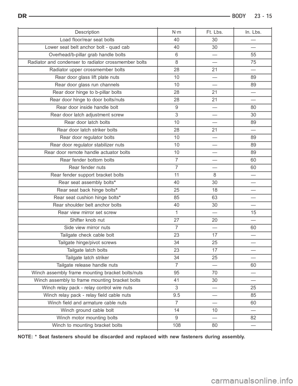
Description Nꞏm Ft. Lbs. In. Lbs.
Load floor/rear seat bolts 40 30 —
Lower seat belt anchor bolt - quad cab 40 30 —
Overhead/b-pillar grab handle bolts 6 — 55
Radiator and condenser to radiator crossmember bolts 8 — 75
Radiator upper crossmember bolts 28 21 —
Rear door glass lift plate nuts 10 — 89
Rear door glass run channels 10 — 89
Rear door hinge to b-pillar bolts 28 21 —
Rear door hinge to door bolts/nuts 28 21 —
Rear door inside handle bolt 9 — 80
Rear door latch adjustment screw 3 — 30
Rear door latch bolts 10 — 89
Rear door latch striker bolts 28 21 —
Rear door regulator bolts 10 — 89
Rear door regulatorstabilizer nuts 10 — 89
Rear door remote handle actuator bolts 10 — 89
Rear fender bottom bolts 7 — 60
Rear fender nuts 7 — 60
Rear fender support bracket bolts 11 8 —
Rear seat assembly bolts*40 30 —
Rear seat back hinge bolts*25 18 —
Rear seat cushion hinge bolts*85 63 —
Rear shoulder belt anchor bolts 40 30 —
Rear view mirror set screw 1 — 15
Shifter knob nut 27 20 —
Side view mirror nuts 7 — 60
Tailgate check cable bolt 23 17 —
Tailgate hinge/pivot screws 34 25 —
Tailgate latch bolts 23 17 —
Tailgate latch striker 34 25 —
Tailgate release handle nuts 7 — 60
Winch assembly frame mounting bracket bolts/nuts 95 70 —
Winch assembly to frame mounting bracket bolts 41 30 —
Winch relay pack - relay control wire nuts 3 — 25
Winch relay pack - relay field cable nuts 9.5 — 85
Winch field and armature cable nuts 7 — 60
Winch ground cable bolt 14 10 —
Winch motor mounting bolts 9 — 82
Winch to mounting bracket bolts 108 80 —
NOTE: * Seat fasteners should be discarded and replaced with new fastenersduring assembly.
Page 4365 of 5267
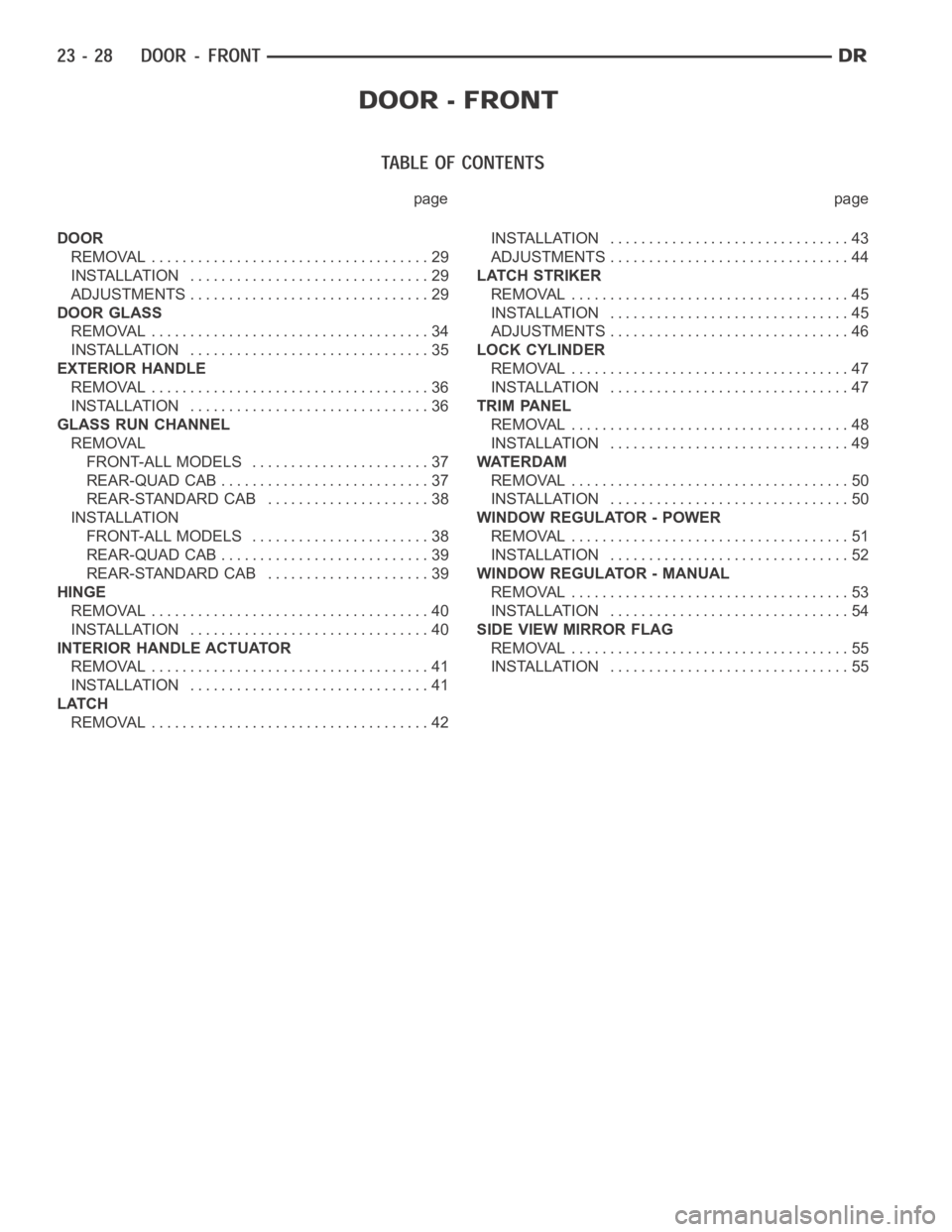
page page
DOOR
REMOVAL .................................... 29
INSTALLATION ............................... 29
ADJUSTMENTS ............................... 29
DOOR GLASS
REMOVAL .................................... 34
INSTALLATION ............................... 35
EXTERIOR HANDLE
REMOVAL .................................... 36
INSTALLATION ............................... 36
GLASS RUN CHANNEL
REMOVAL
FRONT-ALL MODELS ....................... 37
REAR-QUAD CAB ........................... 37
REAR-STANDARD CAB ..................... 38
INSTALLATION
FRONT-ALL MODELS ....................... 38
REAR-QUAD CAB ........................... 39
REAR-STANDARD CAB ..................... 39
HINGE
REMOVAL .................................... 40
INSTALLATION ............................... 40
INTERIOR HANDLE ACTUATOR
REMOVAL .................................... 41
INSTALLATION ............................... 41
LATCH
REMOVAL .................................... 42INSTALLATION ............................... 43
ADJUSTMENTS ............................... 44
LATCH STRIKER
REMOVAL .................................... 45
INSTALLATION ............................... 45
ADJUSTMENTS ............................... 46
LOCK CYLINDER
REMOVAL .................................... 47
INSTALLATION ............................... 47
TRIM PANEL
REMOVAL .................................... 48
INSTALLATION ............................... 49
WATERDAM
REMOVAL .................................... 50
INSTALLATION ............................... 50
WINDOW REGULATOR - POWER
REMOVAL .................................... 51
INSTALLATION ............................... 52
WINDOW REGULATOR - MANUAL
REMOVAL .................................... 53
INSTALLATION ............................... 54
SIDE VIEW MIRROR FLAG
REMOVAL .................................... 55
INSTALLATION ............................... 55
Page 4392 of 5267
SIDE VIEW MIRROR FLAG
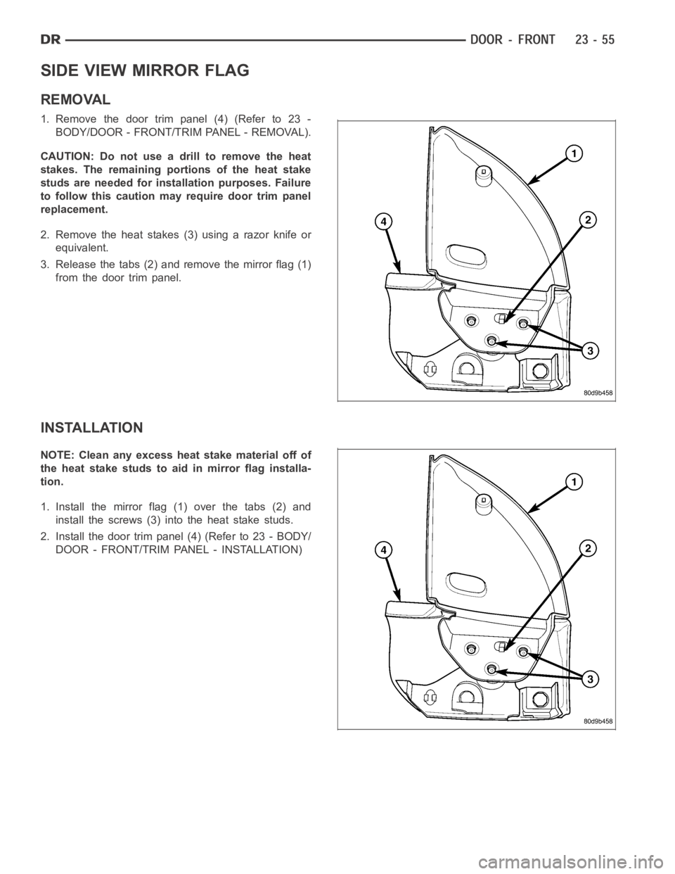
REMOVAL
1. Remove the door trim panel (4) (Refer to 23 -
BODY/DOOR - FRONT/TRIM PANEL - REMOVAL).
CAUTION: Do not use a drill to remove the heat
stakes. The remaining portions of the heat stake
studs are needed for installation purposes. Failure
to follow this caution may require door trim panel
replacement.
2. Remove the heat stakes (3) using a razor knife or
equivalent.
3. Release the tabs (2) and remove the mirror flag (1)
from the door trim panel.
INSTALLATION
NOTE: Clean any excess heat stake material off of
the heat stake studs to aid in mirror flag installa-
tion.
1. Install the mirror flag (1) over the tabs (2) and
install the screws (3) into the heat stake studs.
2. Install the door trim panel (4) (Refer to 23 - BODY/
DOOR - FRONT/TRIM PANEL - INSTALLATION)
Page 4423 of 5267
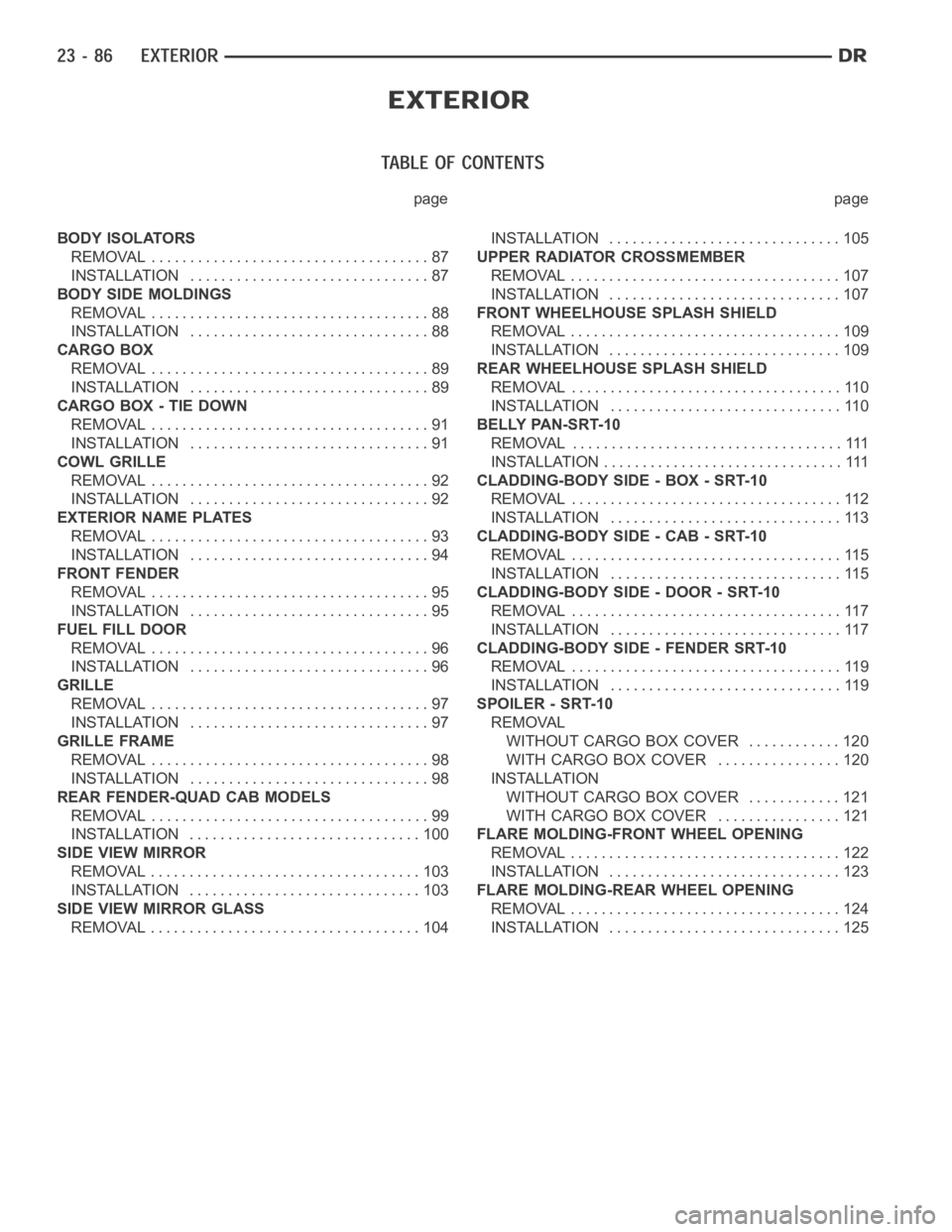
page page
BODY ISOLATORS
REMOVAL .................................... 87
INSTALLATION ............................... 87
BODY SIDE MOLDINGS
REMOVAL .................................... 88
INSTALLATION ............................... 88
CARGO BOX
REMOVAL .................................... 89
INSTALLATION ............................... 89
CARGO BOX - TIE DOWN
REMOVAL .................................... 91
INSTALLATION ............................... 91
COWL GRILLE
REMOVAL .................................... 92
INSTALLATION ............................... 92
EXTERIOR NAME PLATES
REMOVAL .................................... 93
INSTALLATION ............................... 94
FRONT FENDER
REMOVAL .................................... 95
INSTALLATION ............................... 95
FUEL FILL DOOR
REMOVAL .................................... 96
INSTALLATION ............................... 96
GRILLE
REMOVAL .................................... 97
INSTALLATION ............................... 97
GRILLE FRAME
REMOVAL .................................... 98
INSTALLATION ............................... 98
REAR FENDER-QUAD CAB MODELS
REMOVAL .................................... 99
INSTALLATION .............................. 100
SIDE VIEW MIRROR
REMOVAL ................................... 103
INSTALLATION .............................. 103
SIDE VIEW MIRROR GLASS
REMOVAL ................................... 104INSTALLATION .............................. 105
UPPER RADIATOR CROSSMEMBER
REMOVAL ................................... 107
INSTALLATION .............................. 107
FRONT WHEELHOUSE SPLASH SHIELD
REMOVAL ................................... 109
INSTALLATION .............................. 109
REAR WHEELHOUSE SPLASH SHIELD
REMOVAL ................................... 110
INSTALLATION .............................. 110
BELLY PAN-SRT-10
REMOVAL ................................... 111
INSTALLATION ............................... 111
CLADDING-BODY SIDE - BOX - SRT-10
REMOVAL ................................... 112
INSTALLATION .............................. 113
CLADDING-BODY SIDE - CAB - SRT-10
REMOVAL ................................... 115
INSTALLATION .............................. 115
CLADDING-BODY SIDE - DOOR - SRT-10
REMOVAL ................................... 117
INSTALLATION .............................. 117
CLADDING-BODY SIDE - FENDER SRT-10
REMOVAL ................................... 119
INSTALLATION .............................. 119
SPOILER - SRT-10
REMOVAL
WITHOUT CARGO BOX COVER ............ 120
WITH CARGO BOX COVER ................ 120
INSTALLATION
WITHOUT CARGO BOX COVER ............ 121
WITH CARGO BOX COVER ................ 121
FLARE MOLDING-FRONT WHEEL OPENING
REMOVAL ................................... 122
INSTALLATION .............................. 123
FLARE MOLDING-REAR WHEEL OPENING
REMOVAL ................................... 124
INSTALLATION .............................. 125