2006 DODGE RAM SRT-10 automatic transmission
[x] Cancel search: automatic transmissionPage 2889 of 5267
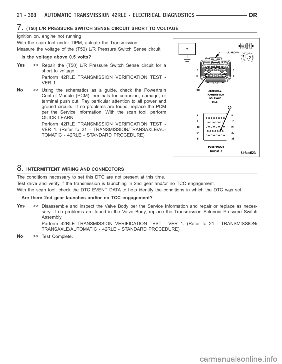
7.(T50) L/R PRESSURE SWITCH SENSE CIRCUIT SHORT TO VOLTAGE
Ignition on, engine not running.
With the scan tool under TIPM, actuate the Transmission.
Measure the voltage of the (T50) L/R Pressure Switch Sense circuit.
Is the voltage above 0.5 volts?
Ye s>>
Repair the (T50) L/R PressureSwitch Sense circuit for a
short to voltage.
Perform 42RLE TRANSMISSION VERIFICATION TEST -
VER 1.
No>>
Using the schematics as a guide, check the Powertrain
Control Module (PCM) terminals for corrosion, damage, or
terminal push out. Pay particular attention to all power and
ground circuits. If no problems are found, replace the PCM
per the Service Information.With the scan tool, perform
QUICK LEARN
Perform 42RLE TRANSMISSION VERIFICATION TEST -
VER 1. (Refer to 21 - TRANSMISSION/TRANSAXLE/AU-
TOMATIC - 42RLE - STANDARD PROCEDURE)
8.INTERMITTENT WIRING AND CONNECTORS
The conditions necessary to set this DTC are not present at this time.
Test drive and verify if the transmission is launching in 2nd gear and/or noTCC engagement.
With the scan tool, check the DTC EVENT DATA to help identify the conditionsin which the DTC was set.
Are there 2nd gear launches and/or no TCC engagement?
Ye s>>
Disassemble and inspect the Valve Body per the Service Information and repair or replace as neces-
sary. If no problems are found in the Valve Body, replace the Transmission Solenoid Pressure Switch
Assembly.
Perform 42RLE TRANSMISSION VERIFICATION TEST - VER 1. (Refer to 21 - TRANSMISSION/
TRANSAXLE/AUTOMATIC - 42RLE - STANDARD PROCEDURE)
No>>
Te s t C o m p l e t e .
Page 2891 of 5267
When Monitored:
Every 7 ms when doing PEMCC or FEMCC.
Set Condition:
Must be in partial or full EMCC. The DTC is set if L/R pressure is detected high for the fourth time.
Possible Causes
RELATED DTC P0841 PRESENT
DTC EVENT DATA SHOWS TRS CODE TR2 - SHIFT LEVER OR MANUAL CONTROL VALVE IN A INVA L I D
POSITION
SHIFTER CABLE OUT OF ADJUSTMENT
SOLENOID SWITCH VALVE STICKING IN ITS BORE
(T50) L/R PRESSURE SWITCH SENSE CIRCUIT OPEN
(T50) L/R PRESSURE SWITCH SENSE CIRCUIT SHORT TO GROUND
(T50) L/R PRESSURE SWITCH SENSE CIRCUIT SHORT TO VOLTAGE
VA LV E B O D Y
POWERTRAIN CONTROL MODULE
Always perform the Pre-Diagnostic Troubleshooting procedure before proceeding. (Refer to 21 - TRANSMIS-
SION/TRANSAXLE/AUTOMATIC - 42RLE - STANDARD PROCEDURE)
Theory of Operation
The Solenoid Switch Valve, an internal, hydraulically operated valve, controls the direction of the transmission fluid
when the L/R solenoid is energized. When the solenoid switch valve is in thedownshifted position and the L/R
solenoid is energized, fluid is directed to the L/R element for 1st gear. When the solenoid switch valve is In the
up-shifted position (2nd, 3rd, and 4th gear) and the L/R solenoid is energized, fluid is directed into the Lockup
Switch Valve which controls the Torque Converter Clutch. When doing PEMCCor FEMCC, the L/R pressure switch
should indicate no pressure if the solenoid switch valve is in the L/R position. If the L/R pressure switch indicates
pressure for some time while in partial or full EMCC, the EMCC operation is aborted and momentarily inhibited to
avoid accidental application of the L/R clutch. EMCC is attempted again when there is no L/R pressure. The fourth
detection of L/R pressure while in PEMCC or FEMCC will result in setting theDTC. Torque converter EMCC oper-
ation inhibited. MIL on after 5 min. of substituted operation.
Diagnostic Test
1.DETERMINING IF RELATED DTC’S ARE PRESENT
With the scan tool, check for other Transmission DTC’s
Is the DTC P0841 present also?
Ye s>>
Refer to the Transmission category and perform the appropriate symptom.
No>>
Go To 2
2.CHECK THE DTC EVENT DATA FOR TRS CODE TR2
With the scan tool, check the DTC EVENT DATA for P1776.
Does the DTC EVENT DATA show a TRS Code of TR2?
Ye s>>
This indicates the shift lever and the manual control valve were in an invalid position between Neutral
and OD. Check the shifter cable for: proper adjustment, binding, friction, improper routing, or the shifter
was moved in transit. Repair as necessary.
Perform 42RLE TRANSMISSION VERIFICATION TEST - VER 1. (Refer to 21 - TRANSMISSION/
TRANSAXLE/AUTOMATIC - 42RLE - STANDARD PROCEDURE)
No>>
Go To 3
Page 2892 of 5267
3.CHECK TO SEE IF DTC P1776 IS CURRENT
With the scan tool, check the STARTS SINCE SET counter for P1776.
NOTE: This counter only applies to the last DTC set.
Is the status Active or is the STARTS SINCE SET counter 2 or less for this DTC?
Ye s>>
Go To 4
No>>
Go To 9
4.CHECK THE PCM AND WIRING USING THE TRANSMISSION SIMULATOR
Turn the ignition off to the lock position.
Remove the Ignition Switch Feed fuse from the TIPM.
CAUTION: Removal of the Ignition Switch Feed fuse from the TIPM will prevent the vehicle from being
startedingear.
WARNING: The Ignition Switch Feed fuse must be removed from the TIPM. Failure to do so can result in
personal injury or death.
Install the Transmission Simulator,Miller tool #8333 and the ElectronicTransmission Adapter kit.
Ignition on, engine not running.
With the Transmission Simulator, turn the Pressure Switch selector switchtoL/R.
With the scan tool, monitor the L/R Pressure Switch State while pressing the Pressure Switch Test button.
Did the Pressure Switch state change from open to closed when the test button was pressed?
Ye s>>
Go To 5
No>>
Go To 6
5.CHECK THE SOLENOID SWITCH VALVE FOR STICKING
Remove the transmission oil pan and Valve body and inspect the Solenoid Switch Valve for sticking in its bore,
repair or replace as necessary.
NOTE: This DTC may be caused by debris lodged in the Transmission Solenoid Switch Valve bore. If debris
is found, clean the valve body and reassemble the transmission per the Service Information.
With the scan tool, record the DTC EVENT DATA for P1776 and erase DTCs.
Reassemble the transmission and test drive the vehicle. Try to duplicate the original set conditions using the DTC
EVENT DATA recorded earlier.
With the scan tool, check Transmission DTCs.
Did the DTC P1776 reset?
Ye s>>
Replace the Transmission Solenoid Assembly per the Service Information.
Perform 42RLE TRANSMISSION VERIFICATION TEST - VER 1. (Refer to 21 - TRANSMISSION/
TRANSAXLE/AUTOMATIC - 42RLE - STANDARD PROCEDURE)
No>>
Te s t C o m p l e t e
Perform 42RLE TRANSMISSION VERIFICATION TEST - VER 1. (Refer to 21 - TRANSMISSION/
TRANSAXLE/AUTOMATIC - 42RLE - STANDARD PROCEDURE)
Page 2894 of 5267
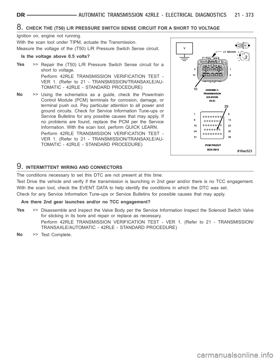
8.CHECK THE (T50) L/R PRESSURE SWITCH SENSE CIRCUIT FOR A SHORT TO VOLTAGE
Ignition on, engine not running.
With the scan tool under TIPM, actuate the Transmission.
Measure the voltage of the (T50) L/R Pressure Switch Sense circuit.
Is the voltage above 0.5 volts?
Ye s>>
Repair the (T50) L/R PressureSwitch Sense circuit for a
short to voltage.
Perform 42RLE TRANSMISSION VERIFICATION TEST -
VER 1. (Refer to 21 - TRANSMISSION/TRANSAXLE/AU-
TOMATIC - 42RLE - STANDARD PROCEDURE)
No>>
Using the schematics as a guide, check the Powertrain
Control Module (PCM) terminals for corrosion, damage, or
terminal push out. Pay particular attention to all power and
ground circuits. Check for Service Information Tune-ups or
Service Bulletins for any possible causes that may apply. If
no problems are found, replace the PCM per the Service
Information. With the scan tool, perform QUICK LEARN.
Perform 42RLE TRANSMISSION VERIFICATION TEST -
VER 1. (Refer to 21 - TRANSMISSION/TRANSAXLE/AU-
TOMATIC - 42RLE - STANDARD PROCEDURE)
9.INTERMITTENT WIRING AND CONNECTORS
The conditions necessary to set this DTC are not present at this time.
Test Drive the vehicle and verify if the transmission is launching in 2nd gear and/or there is no TCC engagement.
With the scan tool, check the EVENT DATAto help identify the conditions in which the DTC was set.
Check for any Service Information Tune-ups or Service Bulletins for possible causes that may apply.
Are there 2nd gear launches and/or no TCC engagement?
Ye s>>
Disassemble and inspect the Valve Body per the Service Information Inspect the Solenoid Switch Valve
for sticking in its bore and repair or replace as necessary.
Perform 42RLE TRANSMISSION VERIFICATION TEST - VER 1. (Refer to 21 - TRANSMISSION/
TRANSAXLE/AUTOMATIC - 42RLE - STANDARD PROCEDURE)
No>>
Te s t C o m p l e t e .
Page 2895 of 5267
P1790-FAULT IMMEDIATELY AFTER SHIFT
For a complete wiring diagramRefer to Section 8W.
When Monitored:
After a Gear Ratio Error code is stored.
Set Condition:
After a Gear Ratio Error DTC has already been set. The DTC is set if the fault happened within 1.3 seconds
of a shift. The DTC set time will vary from 1.214 seconds to 15 seconds.
Possible Causes
FAULT AFTER SHIFT
Always perform the 42RLE Pre-Diagnostic Troubleshooting procedure before proceeding. (Refer to 21 -
TRANSMISSION/TRANSAXLE/AUTOMATIC - 42RLE - STANDARD PROCEDURE)
Theory of Operation
This DTC is not stored alone. It is stored if a Gear Ratio DTC is detected immediately after shift. The existence of
DTC P1790 indicates a mechanical or hydraulic (not electrical) related problems. It should be noted, however, that
all mechanical problems don’t necessarily result in DTC P1790. When this DTC exists, diagnosing the system
should be based on the associated DTC and only mechanical causes should be considered.
Diagnostic Test
1.FAULT AFTER SHIFT
This DTC is set along with a Gear Ratio DTC. Perform the appropriate test forthe Gear Ratio DTC stored.
NOTE: Check Pending DTCs or 1 trip failures if there are no Active or Stored Gear Ratio DTCs.
If there are no possible causes remaining, view repair.
Repair
Refer to the Transmission category and perform the appropriate symptom.
Perform 42RLE TRANSMISSION VERIFICATION TEST - VER 1. (Refer to 21 - TRANSMISSION/
TRANSAXLE/AUTOMATIC - 42RLE - STANDARD PROCEDURE)
Page 2897 of 5267
When Monitored:
Every 7msec after a controller reset with transmission in neutral.
Set Condition:
After a PCM reset in neutral and Input and Output sensor ratio equals 2.50 to1.0 ± 50.0 RPM.
Possible Causes
SPEED SENSOR GROUND CIRCUIT OPEN
POWERTRAIN CONTROL MODULE
Always perform the 42RLE Pre-Diagnostic Troubleshooting procedure before proceeding. (Refer to 21 -
TRANSMISSION/TRANSAXLE/AUTOMATIC - 42RLE - STANDARD PROCEDURE)
Theory of Operation
The input and output speed sensors use a common ground circuit. The loss of this common ground results in the
input signal being sensed for both. After a reset in neutral, and after observing a specific ratio, the Speed Check
Fault Counter will increment. Because the speed sensors and the thermistor share the same ground circuit, this
DTC may indicate a loss of the common speed sensor ground. In some cases thisfault will cause a Gear Ratio
Error DTC to be set.
Diagnostic Test
1.PCM AND WIRING
Turn the ignition off to the lock position.
Remove the Ignition Switch Feed fuse from the TIPM.
CAUTION: Removal of the Ignition Switch Feed fuse from the TIPM will prevent the vehicle from being
startedingear.
WARNING: The Ignition Switch Feed fuse must be removed from the TIPM. Failure to do so can result in
personal injury or death.
Install the Transmission Simulator,Miller tool #8333 and the ElectronicTransmission Adapter kit 8333-1A.
Ignition on, engine not running.
With the Transmission Simulator, set the
Input/Output Speedswitch toONand the rotary switch to the3000/
1250
position.
With the scan tool, monitor the Input and Output Speed Sensor readings.
Does the Input Speed read 3000 RPM and the Output Speed read 1250 RPM, ± 50 RPM?
Ye s>>
Go To 2
No>>
Go To 3
Page 2898 of 5267

2.(T13) SPEED SENSOR GROUND CIRCUIT OPEN
Turn the ignition off to the lock position.
Disconnect the PCM C4 harness connector.
Disconnect the Input and Output Speed Sensor harness connectors.
CAUTION: Do not probe the PCM harness connectors. Probing the
PCM harness connectors will damage the PCM terminals resulting
in poor terminal to pin connection. Install Miller tool #8815 to per-
form diagnosis.
Measure the resistance of both of the (T13) Speed Sensor Ground cir-
cuits from the appropriate terminal of special tool #8815 to the Input
and Output Speed Sensor harness connectors.
Is the resistance above 5.0 ohms on either circuit?
Ye s>>
Repair the (T13) Speed Sensor Ground circuit for an open.
Perform 42RLE TRANSMISSION VERIFICATION TEST -
VER 1. (Refer to 21 - TRANSMISSION/TRANSAXLE/AU-
TOMATIC - 42RLE - STANDARD PROCEDURE)
No>>
Using the schematics as a guide, check the Powertrain
Control Module (PCM) terminals for corrosion, damage, or
terminal push out. Pay particular attention to all power and
ground circuits. If no problems are found, replace the PCM
per the Service Information.With the scan tool, perform
QUICK LEARN
Perform 42RLE TRANSMISSION VERIFICATION TEST - VER 1. (Refer to 21 - TRANSMISSION/
TRANSAXLE/AUTOMATIC - 42RLE - STANDARD PROCEDURE)
3.INTERMITTENT WIRING AND CONNECTORS
The conditions necessary to set the DTC are not present at this time.
Using the schematics as a guide, inspect the wiring and connectors specifictothiscircuit.
Wiggle the wires while checking for shorted and open circuits.
With the scan tool, check the DTC EVENT DATA to help identify the conditionsin which the DTC was set.
Were there any problems found?
Ye s>>
Repair as necessary.
Perform 42RLE TRANSMISSION VERIFICATION TEST - VER 1. (Refer to 21 - TRANSMISSION/
TRANSAXLE/AUTOMATIC - 42RLE - STANDARD PROCEDURE)
No>>
Te s t C o m p l e t e .
Page 2899 of 5267
P1797-MANUAL SHIFT OVERHEAT
For a complete wiring diagramRefer to Section 8W.
When Monitored:
Continuously with engine running.
Set Condition:
If the Engine Temperature exceeds 123° C (255° F) or the Transmission Temperature exceeds 135° C (275° F)
while in AutoStick
mode. Note: Aggressive driving or driving in low for extended periods of time will set this
DTC.
Possible Causes
MANUAL SHIFT OVERHEAT
Always perform the 42RLE Pre-Diagnostic Troubleshooting procedure before proceeding. (Refer to 21 -
TRANSMISSION/TRANSAXLE/AUTOMATIC - 42RLE - STANDARD PROCEDURE)
Theory of Operation
The major cause of heat build up in the transmission is torque converter slip.WiththetransmissionintheAuto-
Stick
mode, the torque converter can slip during aggressive driving or heavy loading conditions such as trailer
towing or driving up steep grades. In the non AutoStick
mode, internal controller logic prevents the transmission
from overheating by managing the shift and EMCC schedule. In the AutoStick
mode, when the transmission or
engine temperature approaches an overheat condition, the manual shift overheat DTC sets and the AutoStick
mode is temporarily suspended until the temperature returns to normal.
Diagnostic Test
1.MANUAL SHIFT OVERHEAT
This is an informational DTC only.
With the scan tool, check the DTC EVENT DATA to help identify the conditionsin which the DTC was set.
Check the engine and transmission cooling system for proper operation.
Check the Radiator Cooling Fan operation.
Check the Transmission Cooling operation.
Check the Transmission Fluid Level per the Service Information to verify that it is not overfilled.
NOTE: Aggressive driving or driving in low for extended periods of time will set this DTC.
If there are no possible causes remaining, view repair.
Repair
If the Transmission Fluid is low, repair any Transmission Fluid leak as necessary and adjust the Trans-
mission Fluid Level per the Service Information. Refer to Service Information for the related symptoms
and repair as necessary.
Perform 42RLE TRANSMISSION VERIFICATION TEST - VER 1. (Refer to 21 - TRANSMISSION/
TRANSAXLE/AUTOMATIC - 42RLE - STANDARD PROCEDURE)