Page 3056 of 5267
INSTALLATION
1. Install the pressure control solenoid (1) and line
pressure sensor (2) into the valve body.
2. Install the screws (6) to hold the pressure control
solenoid (1) and line pressure sensor (2) to the
valve body.
3. Install the electrical connectors to the pressure
control solenoid (1) and the line pressure sensor
(2).
4. Install the valve body into the transmission. (Refer
to 21 - TRANSMISSION/TRANSAXLE/AUTOMATIC
- 42RLE/VALVE BODY - INSTALLATION)
Page 3057 of 5267
MECHANISM-SHIFT
DESCRIPTION
The gear shift mechanism provides six shift positions which are:
Park (P)
Reverse (R)
Neutral (N)
Drive (D)
Manual second (2)
Manual low (1)
OPERATION
MANUAL LOW (1) range provides FIRST gear only. Overrun braking is also provided in this range. MANUAL SEC-
OND (2) range provides FIRST and SECOND gear only.
DRIVE range provides FIRST, SECOND, THIRD and OVERDRIVE FOURTH gear ranges. The shift into OVER-
DRIVE FOURTH gear range occurs only after the transmission has completed the shift into D THIRD gear range.
No further movement of the shift mechanism is required to complete the 3-4 shift.
The FOURTH gear upshift occurs automatically when the overdrive selectorswitch is in the ON position. An upshift
to FOURTH gear may not occur or may be delayed in some of the possible shift schedules. (Refer to 8 - ELEC-
TRICAL/ELECTRONIC CONTROL MODULES/TRANSMISSION CONTROL MODULE - OPERATION)
Page 3061 of 5267

GEAR L/R 2/4 OD
ROPOPOP
P/N CL OP OP
1st CL OP OP
2nd OP CL OP
DOPOPCL
OD OP CL CL
OP = OPEN
CL = CLOSED
A Diagnostic Trouble Code (DTC) will set if the TCM senses any switch open orclosed at the wrong time in a given
gear.
The TCM also tests the 2/4 and OD pressure switches when they are normally off (OD and 2/4 are tested in 1st
gear, OD in 2nd gear, and 2/4 in 3rd gear). The test simply verifies that theyare operational, by looking for a closed
state when the corresponding elementis applied. Immediately after a shift into 1st, 2nd, or 3rd gear with the engine
speed above 1000 rpm, the TCM momentarily turns on element pressure to the 2/4 and/or OD clutch circuits to
identify that the appropriate switch has closed. If it doesn’t close, it istested again. If the switch fails to close the
second time, the appropriate Diagnostic Trouble Code (DTC) will set.
REMOVAL
NOTE: If the Solenoid/Pressure Switch Assembly is being replaced, the Quick Learn Procedure must be per-
formed. (Refer to 8 - ELECTRICAL/ELECTRONIC CONTROL MODULES/TRANSMISSION CONTROL MODULE
- STANDARD PROCEDURE)
1. Raise vehicle on hoist.
2. Remove valve body assembly from transmission.
(Refer to 21 - TRANSMISSION/AUTOMATIC -
42RLE/VALVE BODY - REMOVAL)
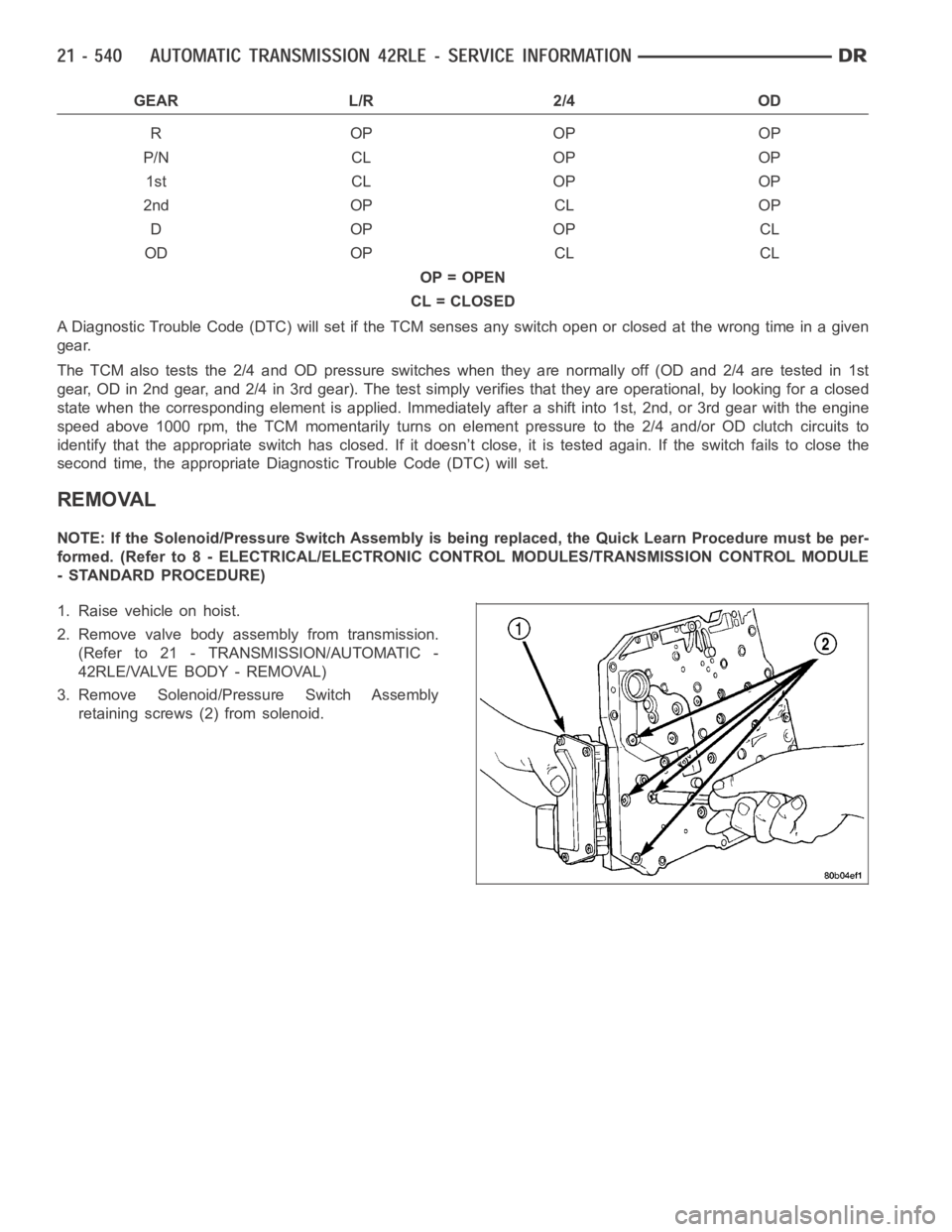
3. Remove Solenoid/Pressure Switch Assembly
retaining screws (2) from solenoid.
Page 3062 of 5267
4. Remove Solenoid/Pressure Switch Assembly (1)
and screen from valve body (2).
INSTALLATION
NOTE: If the Solenoid/Pressure Switch assembly is being replaced, the Quick Learn Procedure must be per-
formed. (Refer to 8 - ELECTRICAL/ELECTRONIC CONTROL MODULES/TRANSMISSION CONTROL MODULE
- STANDARD PROCEDURE)
1. Install Solenoid/Pressure Switch Assembly (1) and
screen (3) to the separator and transfer plates.
2. Install and tighten retaining screws (2) to 5.5 Nꞏm
(50 in. lbs.) torque.
3. Install valve body. (Refer to 21 - TRANSMISSION/
AUTOMATIC - 42RLE/VALVE BODY - INSTALLA-
TION)
Page 3069 of 5267

TORQUE CONVERTER CLUTCH (TCC)
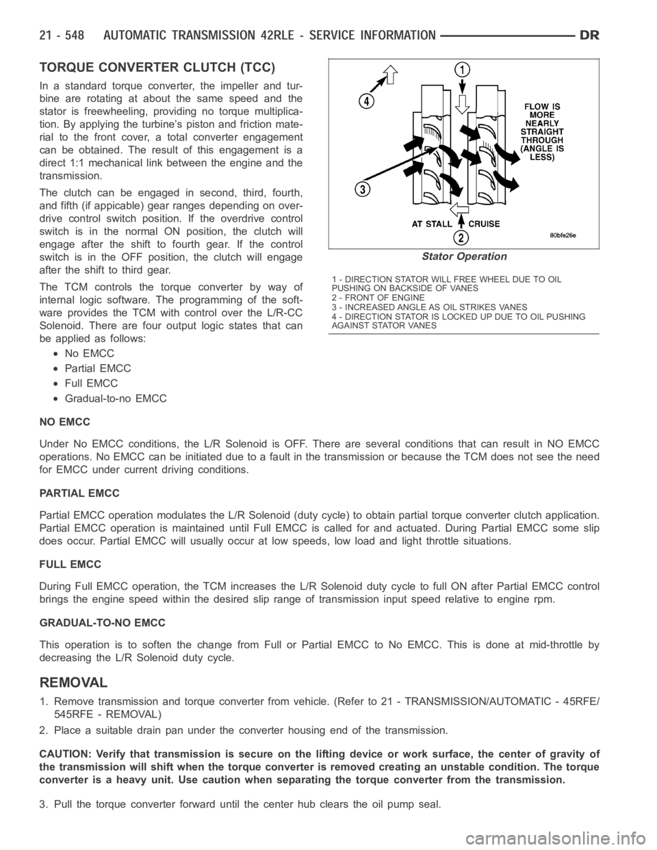
In a standard torque converter, the impeller and tur-
bine are rotating at about the same speed and the
stator is freewheeling, providing no torque multiplica-
tion. By applying the turbine’s piston and friction mate-
rial to the front cover, a total converter engagement
can be obtained. The result of this engagement is a
direct 1:1 mechanical link between the engine and the
transmission.
The clutch can be engaged in second, third, fourth,
and fifth (if appicable) gear ranges depending on over-
drive control switch position. If the overdrive control
switch is in the normal ON position, the clutch will
engage after the shift to fourth gear. If the control
switch is in the OFF position, the clutch will engage
after the shift to third gear.
The TCM controls the torque converter by way of
internal logic software. The programming of the soft-
ware provides the TCM with control over the L/R-CC
Solenoid. There are four output logic states that can
be applied as follows:
No EMCC
Partial EMCC
Full EMCC
Gradual-to-no EMCC
NO EMCC
Under No EMCC conditions, the L/R Solenoid is OFF. There are several conditions that can result in NO EMCC
operations. No EMCC can be initiated due to a fault in the transmission or because the TCM does not see the need
for EMCC under current driving conditions.
PARTIAL EMCC
Partial EMCC operation modulates the L/R Solenoid (duty cycle) to obtain partial torque converter clutch application.
Partial EMCC operation is maintaineduntil Full EMCC is called for and actuated. During Partial EMCC some slip
does occur. Partial EMCC will usually occur at low speeds, low load and light throttle situations.
FULL EMCC
During Full EMCC operation, the TCM increases the L/R Solenoid duty cycle to full ON after Partial EMCC control
brings the engine speed within the desired slip range of transmission input speed relative to engine rpm.
GRADUAL-TO-NO EMCC
This operation is to soften the change from Full or Partial EMCC to No EMCC. This is done at mid-throttle by
decreasing the L/R Solenoid duty cycle.
REMOVAL
1. Remove transmission and torque converter from vehicle. (Refer to 21 - TRANSMISSION/AUTOMATIC - 45RFE/
545RFE - REMOVAL)
2. Place a suitable drain pan under the converter housing end of the transmission.
CAUTION: Verify that transmission is secure on the lifting device or work surface, the center of gravity of
the transmission will shift when the torque converter is removed creatingan unstable condition. The torque
converter is a heavy unit. Use caution when separating the torque converter from the transmission.
3. Pull the torque converter forward until the center hub clears the oil pumpseal.
Stator Operation
1 - DIRECTION STATOR WILL FREE WHEEL DUE TO OIL
PUSHING ON BACKSIDE OF VANES
2-FRONTOFENGINE
3 - INCREASED ANGLE AS OIL STRIKES VANES
4 - DIRECTION STATOR IS LOCKED UP DUE TO OIL PUSHING
AGAINST STATOR VANES
Page 3075 of 5267
REMOVAL
1. Remove valve body assembly from vehicle. (Refer
to 21 - TRANSMISSION/AUTOMATIC - 42RLE/
VA LV E B O D Y - R E M O VA L )
2. Remove the manual shaft seal (1).
3. Remove manual shaft/TRS retaining screw (1).
4. Slide TRS off of manual valve shaft.
Page 3076 of 5267
INSTALLATION
1. Install the TRS (2) to the manual shaft. Make sure
TRS locating pin rests in manual valve bore slot.
2. Install the TRS/manual shaft retaining screw (1)
and torque to 5 Nꞏm (45 in. lbs.) torque.
3. Install the manual shaft seal (1).
4. Install valve body to the transmission. (Refer to 21
- TRANSMISSION//AUTOMATIC - 42RLE/VALVE
BODY - INSTALLATION)
Page 3079 of 5267
The valves contained within the valve body (1) include the following :
Regulator valve (8)
Solenoid switch valve (7)
Manual valve (5)
Converter clutch switch valve (6)
Converter clutch control valve (4)
Torque converter regulator valve (2)
Low/Reverse switch valve (3)
In addition, the valve body also contains the thermal valve, #2, 3, 4 & 5 check balls and the 2/4 accumulator assem-
bly.
OPERATION
NOTE: (Refer to 21 - TRANSMISSION/AUTOMATIC - 42RLE - SCHEMATICS AND DIAGRAMS) for a visual aid
in determining valve location, operation and design.
Valve Body - Exploded
1-VALVEBODY
2 - T / C R E G U L AT O R VA LV E
3-L/RSWITCHVALVE
4 - CONVERTER CLUTCH CONTROL VALVE
5 - MANUAL VALVE
6 - CONVERTER CLUTCH SWITCH VALVE
7 - SOLENOID SWITCH VALVE
8 - REGULATOR VALVE