2006 DODGE RAM SRT-10 automatic transmission
[x] Cancel search: automatic transmissionPage 3108 of 5267
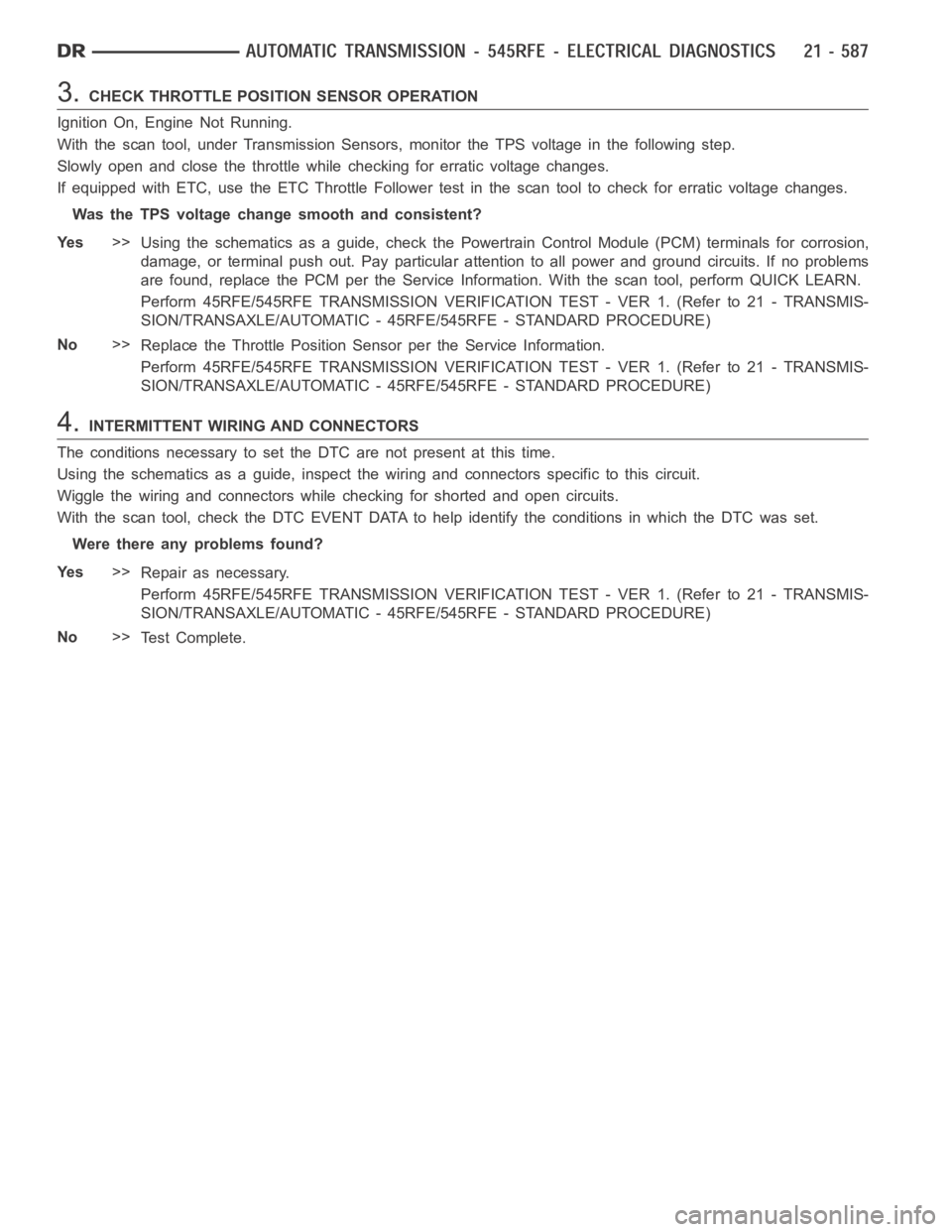
3.CHECK THROTTLE POSITION SENSOR OPERATION
Ignition On, Engine Not Running.
With the scan tool, under Transmission Sensors, monitor the TPS voltage inthe following step.
Slowly open and close the throttle while checking for erratic voltage changes.
IfequippedwithETC,usetheETCThrottleFollowertestinthescantooltocheck for erratic voltage changes.
Was the TPS voltage change smooth and consistent?
Ye s>>
Using the schematics as a guide, check the Powertrain Control Module (PCM)terminals for corrosion,
damage, or terminal push out. Pay particular attention to all power and ground circuits. If no problems
are found, replace the PCM per the Service Information. With the scan tool,perform QUICK LEARN.
Perform 45RFE/545RFE TRANSMISSION VERIFICATION TEST - VER 1. (Refer to 21- TRANSMIS-
SION/TRANSAXLE/AUTOMATIC - 45RFE/545RFE - STANDARD PROCEDURE)
No>>
Replace the Throttle Position Sensor per the Service Information.
Perform 45RFE/545RFE TRANSMISSION VERIFICATION TEST - VER 1. (Refer to 21- TRANSMIS-
SION/TRANSAXLE/AUTOMATIC - 45RFE/545RFE - STANDARD PROCEDURE)
4.INTERMITTENT WIRING AND CONNECTORS
The conditions necessary to set the DTC are not present at this time.
Using the schematics as a guide, inspect the wiring and connectors specifictothiscircuit.
Wiggle the wiring and connectors while checking for shorted and open circuits.
With the scan tool, check the DTC EVENT DATA to help identify the conditionsin which the DTC was set.
Were there any problems found?
Ye s>>
Repair as necessary.
Perform 45RFE/545RFE TRANSMISSION VERIFICATION TEST - VER 1. (Refer to 21- TRANSMIS-
SION/TRANSAXLE/AUTOMATIC - 45RFE/545RFE - STANDARD PROCEDURE)
No>>
Te s t C o m p l e t e .
Page 3109 of 5267
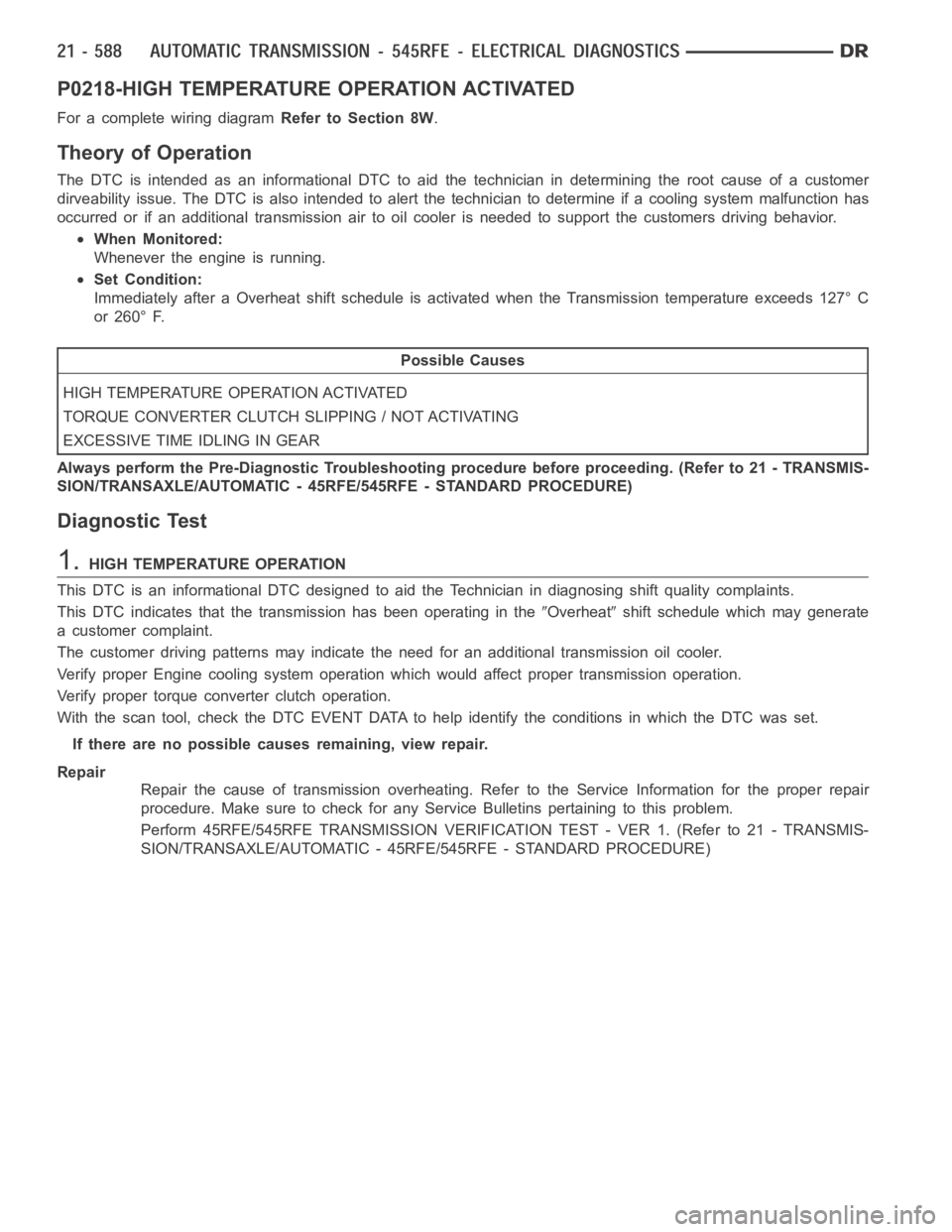
P0218-HIGH TEMPERATURE OPERATION ACTIVATED
For a complete wiring diagramRefer to Section 8W.
Theory of Operation
The DTC is intended as an informational DTC to aid the technician in determining the root cause of a customer
dirveability issue. The DTC is also intended to alert the technician to determine if a cooling system malfunction has
occurred or if an additional transmission air to oil cooler is needed to support the customers driving behavior.
When Monitored:
Whenever the engine is running.
Set Condition:
Immediately after a Overheat shift schedule is activated when the Transmission temperature exceeds 127° C
or 260° F.
Possible Causes
H I G H T E M P E R AT U R E O P E R AT I O N A C T I VAT E D
TORQUE CONVERTER CLUTCH SLIPPING / NOT ACTIVATING
EXCESSIVE TIME IDLING IN GEAR
Always perform the Pre-Diagnostic Troubleshooting procedure before proceeding. (Refer to 21 - TRANSMIS-
SION/TRANSAXLE/AUTOMATIC - 45RFE/545RFE - STANDARD PROCEDURE)
Diagnostic Test
1.HIGH TEMPERATURE OPERATION
This DTC is an informational DTC designed to aid the Technician in diagnosing shift quality complaints.
This DTC indicates that the transmission has been operating in the
Overheatshift schedule which may generate
a customer complaint.
The customer driving patterns may indicate the need for an additional transmission oil cooler.
Verify proper Engine cooling system operation which would affect proper transmission operation.
Verify proper torque converter clutch operation.
With the scan tool, check the DTC EVENT DATA to help identify the conditionsin which the DTC was set.
If there are no possible causes remaining, view repair.
Repair
Repair the cause of transmission overheating. Refer to the Service Information for the proper repair
procedure. Make sure to check for any Service Bulletins pertaining to thisproblem.
Perform 45RFE/545RFE TRANSMISSION VERIFICATION TEST - VER 1. (Refer to 21- TRANSMIS-
SION/TRANSAXLE/AUTOMATIC - 45RFE/545RFE - STANDARD PROCEDURE)
Page 3111 of 5267
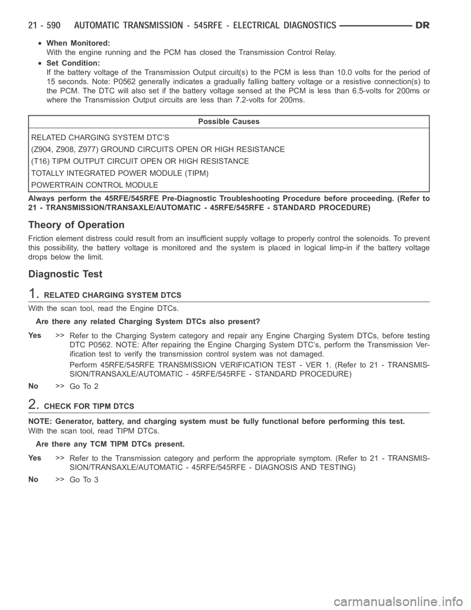
When Monitored:
With the engine running and the PCM has closed the Transmission Control Relay.
Set Condition:
If the battery voltage of the Transmission Output circuit(s) to the PCM is less than 10.0 volts for the period of
15 seconds. Note: P0562 generally indicates a gradually falling battery voltage or a resistive connection(s) to
the PCM. The DTC will also set if the battery voltage sensed at the PCM is lessthan 6.5-volts for 200ms or
where the Transmission Output circuits are less than 7.2-volts for 200ms.
Possible Causes
RELATED CHARGING SYSTEM DTC’S
(Z904, Z908, Z977) GROUND CIRCUITS OPEN OR HIGH RESISTANCE
(T16) TIPM OUTPUT CIRCUIT OPEN OR HIGH RESISTANCE
TOTALLY INTEGRATED POWER MODULE (TIPM)
POWERTRAIN CONTROL MODULE
Always perform the 45RFE/545RFE Pre-Diagnostic Troubleshooting Procedure before proceeding. (Refer to
21 - TRANSMISSION/TRANSAXLE/AUTOMATIC - 45RFE/545RFE - STANDARD PROCEDURE)
Theory of Operation
Friction element distress could result from an insufficient supply voltage to properly control the solenoids. To prevent
this possibility, the battery voltage is monitored and the system is placed in logical limp-in if the battery voltage
drops below the limit.
Diagnostic Test
1.RELATED CHARGING SYSTEM DTCS
With the scan tool, read the Engine DTCs.
Are there any related Charging System DTCs also present?
Ye s>>
Refer to the Charging System category and repair any Engine Charging System DTCs, before testing
DTC P0562. NOTE: After repairing the Engine Charging System DTC’s, perform the Transmission Ver-
ification test to verify the transmission control systemwas not damaged.
Perform 45RFE/545RFE TRANSMISSION VERIFICATION TEST - VER 1. (Refer to 21- TRANSMIS-
SION/TRANSAXLE/AUTOMATIC - 45RFE/545RFE - STANDARD PROCEDURE)
No>>
Go To 2
2.CHECK FOR TIPM DTCS
NOTE: Generator, battery, and charging system must be fully functional before performing this test.
With the scan tool, read TIPM DTCs.
Are there any TCM TIPM DTCs present.
Ye s>>
Refer to the Transmission category and perform the appropriate symptom. (Refer to 21 - TRANSMIS-
SION/TRANSAXLE/AUTOMATIC - 45RFE/545RFE - DIAGNOSIS AND TESTING)
No>>
Go To 3
Page 3112 of 5267
3.CONDITION P0562 PRESENT
With the scan tool, read Transmission DTCs.
With the scan tool, Check the STARTS SINCE SET counter for P0562.
NOTE: This counter only applies to the last DTC set.
Is the STARTS SINCE SET counter set at 0?
Ye s>>
Go To 4
No>>
Go To 7
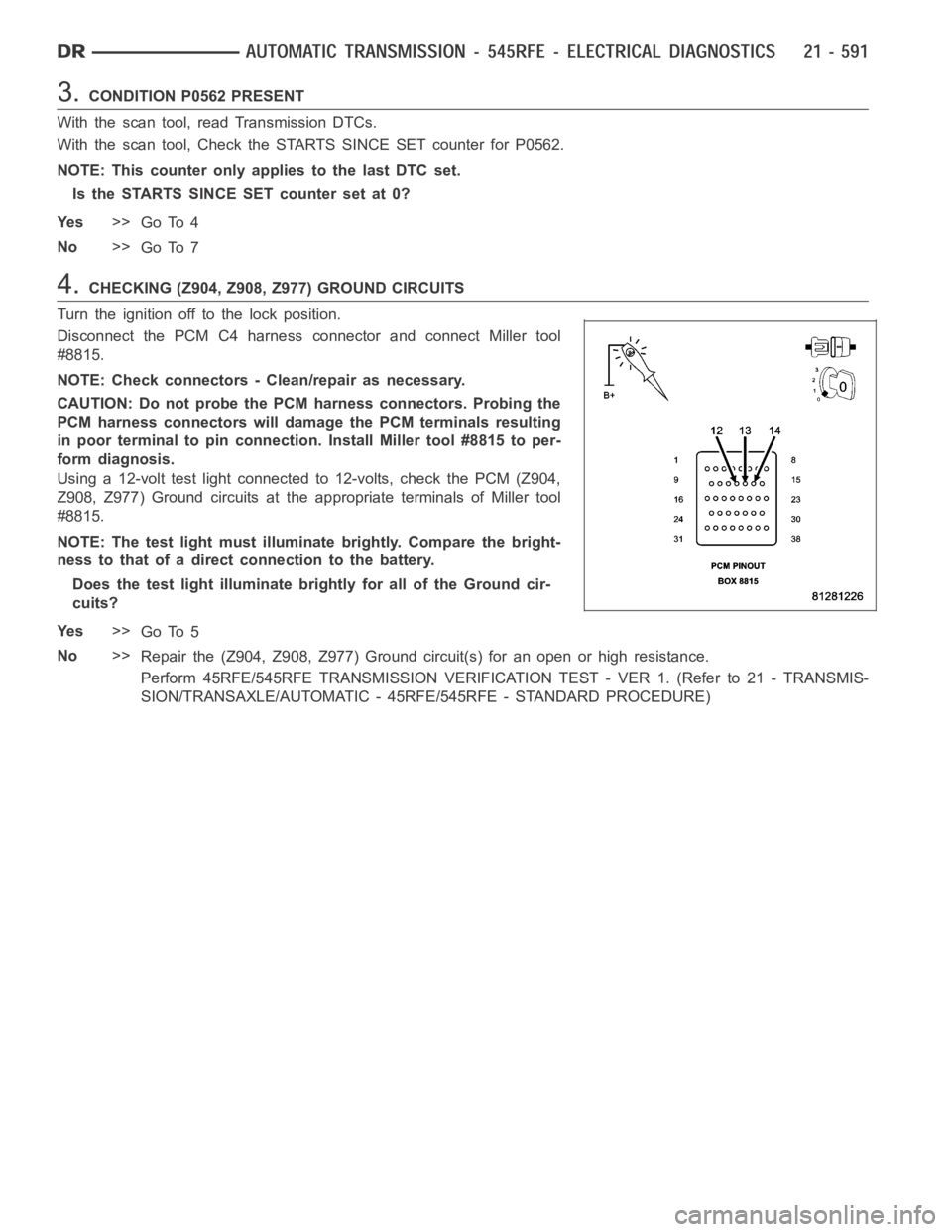
4.CHECKING (Z904, Z908, Z977) GROUND CIRCUITS
Turn the ignition off to the lock position.
Disconnect the PCM C4 harness connector and connect Miller tool
#8815.
NOTE: Check connectors - Clean/repair as necessary.
CAUTION: Do not probe the PCM harness connectors. Probing the
PCM harness connectors will damage the PCM terminals resulting
in poor terminal to pin connection. Install Miller tool #8815 to per-
form diagnosis.
Using a 12-volt test light connected to 12-volts, check the PCM (Z904,
Z908, Z977) Ground circuits at the appropriate terminals of Miller tool
#8815.
NOTE: The test light must illuminate brightly. Compare the bright-
ness to that of a direct connection to the battery.
Does the test light illuminate brightly for all of the Ground cir-
cuits?
Ye s>>
Go To 5
No>>
Repair the (Z904, Z908, Z977) Ground circuit(s) for an open or high resistance.
Perform 45RFE/545RFE TRANSMISSION VERIFICATION TEST - VER 1. (Refer to 21- TRANSMIS-
SION/TRANSAXLE/AUTOMATIC - 45RFE/545RFE - STANDARD PROCEDURE)
Page 3113 of 5267
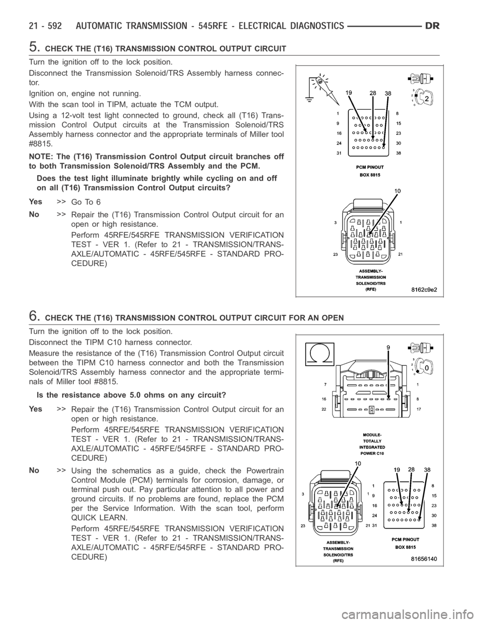
5.CHECK THE (T16) TRANSMISSION CONTROL OUTPUT CIRCUIT
Turn the ignition off to the lock position.
Disconnect the Transmission Solenoid/TRS Assembly harness connec-
tor.
Ignition on, engine not running.
With the scan tool in TIPM, actuate the TCM output.
Using a 12-volt test light connected to ground, check all (T16) Trans-
mission Control Output circuits at the Transmission Solenoid/TRS
Assembly harness connector and the appropriate terminals of Miller tool
#8815.
NOTE: The (T16) Transmission Control Output circuit branches off
to both Transmission Solenoid/TRS Assembly and the PCM.
Does the test light illuminate brightly while cycling on and off
on all (T16) Transmission Control Output circuits?
Ye s>>
Go To 6
No>>
Repair the (T16) Transmission Control Output circuit for an
open or high resistance.
Perform 45RFE/545RFE TRANSMISSION VERIFICATION
TEST - VER 1. (Refer to 21 - TRANSMISSION/TRANS-
AXLE/AUTOMATIC - 45RFE/545RFE - STANDARD PRO-
CEDURE)
6.CHECK THE (T16) TRANSMISSION CONTROL OUTPUT CIRCUIT FOR AN OPEN
Turn the ignition off to the lock position.
Disconnect the TIPM C10 harness connector.
Measure the resistance of the (T16) Transmission Control Output circuit
between the TIPM C10 harness connector and both the Transmission
Solenoid/TRS Assembly harness connector and the appropriate termi-
nals of Miller tool #8815.
Is the resistance above 5.0 ohms on any circuit?
Ye s>>
Repair the (T16) Transmission Control Output circuit for an
open or high resistance.
Perform 45RFE/545RFE TRANSMISSION VERIFICATION
TEST - VER 1. (Refer to 21 - TRANSMISSION/TRANS-
AXLE/AUTOMATIC - 45RFE/545RFE - STANDARD PRO-
CEDURE)
No>>
Using the schematics as a guide, check the Powertrain
Control Module (PCM) terminals for corrosion, damage, or
terminal push out. Pay particular attention to all power and
ground circuits. If no problems are found, replace the PCM
per the Service Information.With the scan tool, perform
QUICK LEARN.
Perform 45RFE/545RFE TRANSMISSION VERIFICATION
TEST - VER 1. (Refer to 21 - TRANSMISSION/TRANS-
AXLE/AUTOMATIC - 45RFE/545RFE - STANDARD PRO-
CEDURE)
Page 3114 of 5267

7.INTERMITTENT WIRING AND CONNECTORS
The conditions necessary to set this DTC are not present at this time.
Using the schematics as a guide, inspect the wiring and connectors specifictothiscircuit.
Wiggle the wires while checking for shorted and open circuits.
With the scan tool, check the DTC EVENT DATA to help identify the conditionsin which the DTC was set.
Where there any problems found?
Ye s>>
Repair as necessary.
Perform 45RFE/545RFE TRANSMISSION VERIFICATION TEST - VER 1. (Refer to 21- TRANSMIS-
SION/TRANSAXLE/AUTOMATIC - 45RFE/545RFE - STANDARD PROCEDURE)
No>>
Te s t C o m p l e t e .
Page 3115 of 5267
P0602-CONTROL MODULE PROGRAMMING ERROR/NOT PROGRAMMED
For a complete wiring diagramRefer to Section 8W
Theory of Operation
The controller is programmed during manufacturing with generic softwareto facilitate testing. However, generic soft-
ware does not have the proper calibrations to control a transmission in a vehicle. The check for generic software is
made at power-up. If generic software is found , the MIL will light immediately and the MIL will stay on even if the
fault is cleared, until the proper software is installed. Note: Transmission will be placed in limp-in mode.
When Monitored:
Check for generic software is made at power-up
Set Condition:
If generic software is found, the MIL will light immediately. This DTC is designed to inform the technician that
the controller still has generic software installed.
Possible Causes
PCM - PROGRAMMING ERROR
Always perform the Pre-Diagnostic Troubleshooting procedure before proceeding. (Refer to 21 - TRANSMIS-
SION/TRANSAXLE/AUTOMATIC - 45RFE/545RFE - STANDARD PROCEDURE)
Diagnostic Test
1.CONTROL MODULE PROGRAMMING ERROR
NOTE: Controller is programmed with generic software and will not allow the correct vehicle Powertrain
management.
With the scan tool.
Record the vehicles controller part number.
Select Use Controller Part Number under the Flash Tab.
Flash the controller with the correct software.
Verify the controller flashed successfully.
Te s t C o m p l e t e
Perform 45RFE/545RFE TRANSMISSION VERIFICATION TEST - VER 1. (Refer to 21- TRANSMIS-
SION/TRANSAXLE/AUTOMATIC - 45RFE/545RFE - STANDARD PROCEDURE)
Page 3116 of 5267
P0604-INTERNAL CONTROL MODULE RAM
For a complete wiring diagramRefer to Section 8W.
Theory of Operation
After the controller is reset (ignition turned to the RUN position), the microprocessor checks the integrity of each
RAM location by writing to it and reading back from it. The read value shouldbe same as value written.
When Monitored:
One time after the controller is reset (ignition turned to the RUN position).
Set Condition:
Whenever the Powertrain Control Module (PCM) detects an internal controller problem.
Possible Causes
POWERORGROUNDCIRCUIT
POWERTRAIN CONTROL MODULE
Always perform the Pre-Diagnostic Troubleshooting procedure before proceeding. (Refer to 21 - TRANSMIS-
SION/TRANSAXLE/AUTOMATIC - 45RFE/545RFE - STANDARD PROCEDURE)
Diagnostic Test
1.CHECK WIRING AND CONNECTORS FOR INTERMITTENT OPERATION
Using the schematics as a guide, check the Powertrain Control Module (PCM)terminals for corrosion, damage, or
terminal push out. Pay particular attention to all power and ground circuits.
NOTE: Due to the integration of the Powertrain and Transmission Control Modules, the transmission part of
the PCM has it’s own specific power and ground circuits.
Wiggle the wires while checking for shorted and open circuits.
Check for any Service Bulletins that may apply.
Were there any problems found?
Ye s>>
Repair the power and/or ground circuits to the PCM and Transmission Control Relay as necessary.
Perform 45RFE/545RFE TRANSMISSION VERIFICATION TEST - VER 1. (Refer to 21- TRANSMIS-
SION/TRANSAXLE/AUTOMATIC - 45RFE/545RFE - STANDARD PROCEDURE)
No>>
Replace the PCM per the Service Information. With the scan tool, perform QUICK LEARN.
Perform 45RFE/545RFE TRANSMISSION VERIFICATION TEST - VER 1. (Refer to 21- TRANSMIS-
SION/TRANSAXLE/AUTOMATIC - 45RFE/545RFE - STANDARD PROCEDURE)