2006 DODGE RAM SRT-10 automatic transmission
[x] Cancel search: automatic transmissionPage 2860 of 5267
When Monitored:
Continuously with ignition on and engine running.
Set Condition:
This DTC will set if the monitored Line Pressure Sensor voltage is greater than or equal to 4.75 volts for the
period of 0.18 seconds
Possible Causes
(T38) LINE PRESSURE SENSOR SIGNAL CIRCUIT OPEN
(K900) SENSOR GROUND CIRCUIT OPEN
(T38) LINE PRESSURE SENSOR SIGNAL CIRCUIT SHORT TO VOLTAGE
LINE PRESSURE SENSOR
POWERTRAIN CONTROL MODULE
Always perform the 42RLE Pre-Diagnostic Troubleshooting procedure before proceeding. (Refer to 21 -
TRANSMISSION/TRANSAXLE/AUTOMATIC - 42RLE - STANDARD PROCEDURE)
Theory of Operation
Line pressure is electronically controlled by the Transmission Control System and is measured by the Line Pressure
Sensor (LPS). The desired line pressure is continuously being compared tothe actual line pressure and is regulated
by electronically changing the dutycycle of the Pressure Control Solenoid (PCS). (5% duty cycle = solenoid off =
max line pressure, 62% duty cycle =solenoid on = min line pressure).
The Transmission Control System calculates the desired line pressure based on inputs from the transmission and
engine. A calculated torque input to the transmission is used as the primary input of the desired line pressure cal-
culation and is called Torque Based Line Pressure. In addition, the line pressure is set to a preset level 827 to 931
kPa (120 to 135 PSI) during shifts and in Park and Neutral to ensure consistent shift quality.
The monitored Line Pressure Sensor voltage should always be between 0.35 and 4.75 volts. Any monitored volt-
ages outside these parameters indicate an Line Pressure Sensor or wiring problem and will cause either DTC
P0934 or P0935 to set.
Diagnostic Test
1.CHECK TO SEE IF DTC IS CURRENT
With the scan tool, Check the STARTS SINCE SET counter for P0935.
NOTE: This counter only applies to the last DTC set.
Is the STARTS SINCE SET counter 2 or less?
Ye s>>
Go To 2
No>>
Go To 6
2.CHECK THE PCM AND WIRING
Turn the ignition off to the lock position.
Remove the Starter Relay.
Remove the Ignition Switch Feed fuse from the TIPM.
CAUTION: Removal of the Ignition Switch Feed fuse from the TIPM will prevent the vehicle from being
startedingear.
WARNING: The Ignition Switch Feed fuse must be removed from the TIPM. Failure to do so can result in
personal injury or death.
Install the Transmission Simulator,Miller tool #8333 and the ElectronicTransmission Adapter kit.
Ignition on, engine not running.
With the scan tool, monitor the Line Pressure.
Using the Transmission Simulator, set the rotary switch to each of the 3 line pressure positions.
Page 2861 of 5267
NOTE: All three scan tool Line Pressure readings should be steady and ± 14 kPa or 2.0 psi of the reading
specified on the Transmission Simulator.
Did the Line Pressure read within ± 14 kPa or 2.0 psi in all three positions?
Ye s>>
Replace the Line Pressure Sensor per the Service Information.
Perform 42RLE TRANSMISSION VERIFICATION TEST - VER 1. (Refer to 21 - TRANSMISSION/
TRANSAXLE/AUTOMATIC - 42RLE - STANDARD PROCEDURE)
No>>
Go To 3
3.CHECK THE (K900) SENSOR GROUND CIRCUIT FOR AN OPEN
Turn the ignition off to the lock position.
Disconnect the Transmission Simulator, Miller tool #8333 and the Elec-
tronic Transmission Adapter kit.
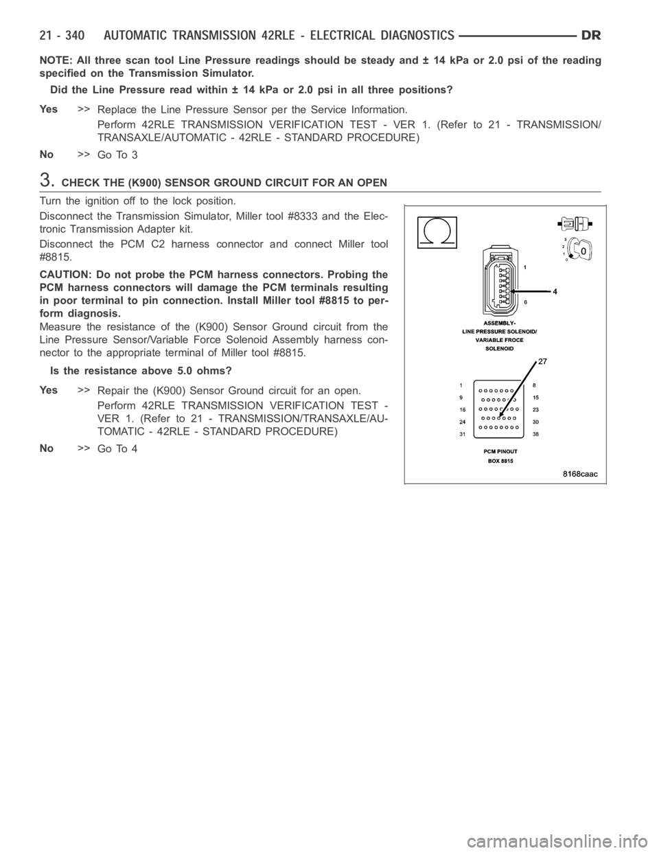
Disconnect the PCM C2 harness connector and connect Miller tool
#8815.
CAUTION: Do not probe the PCM harness connectors. Probing the
PCM harness connectors will damage the PCM terminals resulting
in poor terminal to pin connection. Install Miller tool #8815 to per-
form diagnosis.
Measure the resistance of the (K900) Sensor Ground circuit from the
Line Pressure Sensor/Variable Force Solenoid Assembly harness con-
nector to the appropriate terminal of Miller tool #8815.
Is the resistance above 5.0 ohms?
Ye s>>
Repair the (K900) Sensor Ground circuit for an open.
Perform 42RLE TRANSMISSION VERIFICATION TEST -
VER 1. (Refer to 21 - TRANSMISSION/TRANSAXLE/AU-
TOMATIC - 42RLE - STANDARD PROCEDURE)
No>>
Go To 4
Page 2863 of 5267

6.CHECK WIRING AND CONNECTORS
The conditions necessary to set this DTC are not present at this time.
Using the schematics as a guide, inspect the wiring and connectors specifictothiscircuit.
Wiggle the wires while checking for shorted and open circuits.
With the scan tool, check the DTC EVENT DATA to help identify the conditionsin which the DTC was set.
Where there any problems found?
Ye s>>
Repair as necessary.
Perform 42RLE TRANSMISSION VERIFICATION TEST - VER 1. (Refer to 21 - TRANSMISSION/
TRANSAXLE/AUTOMATIC - 42RLE - STANDARD PROCEDURE)
No>>
Te s t C o m p l e t e .
Page 2864 of 5267
P0944-LOSS OF HYDRAULIC PUMP PRIME
For a complete wiring diagramRefer to Section 8W.
When Monitored:
Every 350 msec
Set Condition:
If the transmission begins to slip in any forward gear, and the pressure switch or switches that should be
closed for a given gear are open, a loss of prime test begins. All available elements (in 1st gear LR, 2/4 and
OD, in 2nd, 3rd, and 4th gear 2/4 and OD) are turned on by the PCM to see if pump prime exists. The code
is set if none of the pressure switches respond. The PCM will continue to runthe loss of prime test until pump
pressure returns. The vehicle will not move or the transmission will slip.Normal operation will continue if pump
prime returns.
Possible Causes
LOW TRANSMISSION FLUID LEVEL
SHIFT LEVER POSITION
PLUGGED TRANSMISSION FILTER
TRANSMISSION OIL PUMP
Always perform the 42RLE Pre-Diagnostic Troubleshooting procedure before proceeding. (Refer to 21 -
TRANSMISSION/TRANSAXLE/AUTOMATIC - 42RLE - STANDARD PROCEDURE)
Theory of Operation
The Loss of Prime Test is used to prevent transmission defaults and erroneous fault codes during temporary loss of
pump prime that may occur with low transmission fluid under severe brakingconditions, start-up, etc. and to point
towards more subtle problems such as a plugged or ruptured oil filter. The Loss of Prime fault is set by a loss of
hydraulic pressure in the transmission system. This condition, if sustained, will result in the vehicle being unable to
move.
Diagnostic Test
1.CHECK TO SEE IF DTC P0944 IS CURRENT
Place the gear selector in park.
Start the engine.
NOTE: The Transmission Temperature must be at least 43° C (110° F) before performing the following steps.
The Transmission must be at operating temperature prior to checking pressure. Cold transmission fluid will result in
higher pressure readings.
Place the Transmission in Reverse.
With the scan tool, observe the Transmission Pressure Switch states.
Are any of the Pressure Switches closed?
Ye s>>
Go To 2
No>>
Go To 4
Page 2865 of 5267
2.INTERMITTENT OPERATION
The conditions necessary to set this DTC are not present at this time.
Test drive the vehicle. Allow the Transmission to shift through all gears and ranges.
Was a delayed engagement and/or a no drive condition present during the testdrive?
Ye s>>
Go To 4
No>>
Go To 3
3.INTERMITTENT WIRING AND CONNECTORS
The conditions necessary to set this DTC are not present at this time.
Using the schematics as a guide, inspect the wiring and connectors specifictothiscircuit.
Wiggle the wiring while checking for shorted and open circuits.
With the scan tool, check the EVENT DATAto help identify the conditions in which the DTC was set.
Were there any problems found?
Ye s>>
Repair as necessary.
Perform 42RLE TRANSMISSION VERIFICATION TEST - VER 1. (Refer to 21 - TRANSMISSION/
TRANSAXLE/AUTOMATIC - 42RLE - STANDARD PROCEDURE)
No>>
Te s t C o m p l e t e .
4.SHIFT LEVER POSITION TEST
With the scan tool, perform a Shift Lever Position test. Follow the instructions on the screen.
Did the Shift Lever Position Test pass?
Ye s>>
Go To 5
No>>
Perform the diagnostic procedure for P0706-CHECK SHIFTER SIGNAL.
Perform 42RLE TRANSMISSION VERIFICATION TEST - VER 1. (Refer to 21 - TRANSMISSION/
TRANSAXLE/AUTOMATIC - 42RLE - STANDARD PROCEDURE)
5.CHECK FOR PLUGGED TRANSMISSION FILTER
Remove the Transmission Pan and inspect the Transmission Fluid and Transmission Filter per the Service Informa-
tion.
Does the Transmission Oil Pan contain excessive debris and/or is the Oil Filter plugged?
Ye s>>
Repair the cause of the plugged Transmission Filter. Refer to the Service Information for the proper
repair procedure.
Perform 42RLE TRANSMISSION VERIFICATION TEST - VER 1. (Refer to 21 - TRANSMISSION/
TRANSAXLE/AUTOMATIC - 42RLE - STANDARD PROCEDURE)
No>>
Replace the Transmission Oil Pump per the Service Information.
Perform 42RLE TRANSMISSION VERIFICATION TEST - VER 1.
Perform 42RLE TRANSMISSION VERIFICATION TEST - VER 1. (Refer to 21 - TRANSMISSION/
TRANSAXLE/AUTOMATIC - 42RLE - STANDARD PROCEDURE)
Page 2866 of 5267
P0992-2/4/OD HYDRAULIC PRESSURE TEST
For a complete wiring diagramRefer to Section 8W.
When Monitored:
In any forward gear with engine speed above 1000 RPM, shortly after a shift and every minute thereafter.
Set Condition:
After a shift into a forward gear, with engine speed greater than 1000 RPM, the PCM momentarily turns on
element pressure to the clutch circuits that do not have pressure to identify that the correct pressure switch
closes. If the pressure switch does not close 2 times the DTC sets.
Possible Causes
CONDITION P0992 PRESENT
Always perform the Pre-Diagnostic Troubleshooting procedure before proceeding. (Refer to 21 - TRANSMIS-
SION/TRANSAXLE/AUTOMATIC - 42RLE - DIAGNOSIS AND TESTING).
Theory of Operation
Pressure switches are normally off or open (no pressure applied) and read high (+12 volts). When an element is
applied, the corresponding pressure switch closes to ground (0 volts) or turns on. The controller tests the OD and
2/4 pressure switches when they are off (when the corresponding friction element is not applied) by briefly applying
the OD and 2/4 elements which will cause the corresponding pressure switchto close. The test verifies that the
switches are operational and that the switch will close when the corresponding element is applied. If a switch fails
to respond, it is re-tested. The MIL illuminates and the transmission system defaults to Limp-in mode.
1.CHECK TO SEE IF DTC P0992 IS CURRENT
NOTE: The vehicle must be driven to set this DTC. The transmission must at operating temperature with the
Engine RPM above 1000 RPM.
This DTC is an indication of both the 2/4 and the O/D Hydraulic Pressure Switch DTCs present.
Perform the diagnostic procedures for both P0845 and P0870.
With the scan tool, check the DTC EVENT DATA to help identify the conditionsin which the DTC was set.
If there are no possible causes remaining, view repair.
Repair
Refer to the Transmission category and perform the diagnostic proceduresfor P0845 and P0870.
Page 2869 of 5267
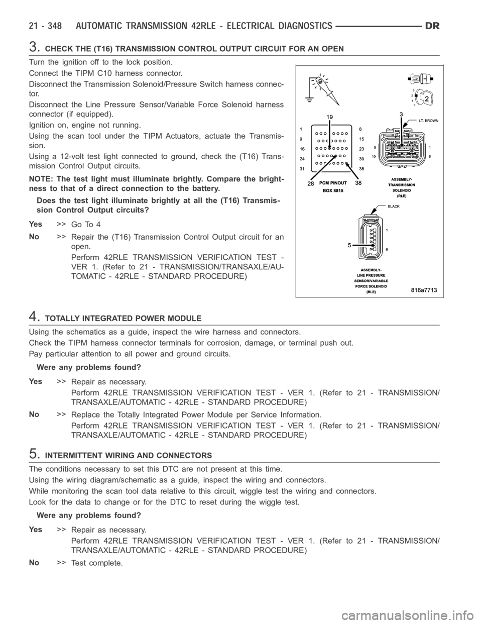
3.CHECK THE (T16) TRANSMISSION CONTROL OUTPUT CIRCUIT FOR AN OPEN
Turn the ignition off to the lock position.
Connect the TIPM C10 harness connector.
Disconnect the Transmission Solenoid/Pressure Switch harness connec-
tor.
Disconnect the Line Pressure Sensor/Variable Force Solenoid harness
connector (if equipped).
Ignition on, engine not running.
Using the scan tool under the TIPM Actuators, actuate the Transmis-
sion.
Using a 12-volt test light connected to ground, check the (T16) Trans-
mission Control Output circuits.
NOTE: The test light must illuminate brightly. Compare the bright-
ness to that of a direct connection to the battery.
Does the test light illuminate brightly at all the (T16) Transmis-
sion Control Output circuits?
Ye s>>
Go To 4
No>>
Repair the (T16) Transmission Control Output circuit for an
open.
Perform 42RLE TRANSMISSION VERIFICATION TEST -
VER 1. (Refer to 21 - TRANSMISSION/TRANSAXLE/AU-
TOMATIC - 42RLE - STANDARD PROCEDURE)
4.TOTALLY INTEGRATED POWER MODULE
Using the schematics as a guide, inspect the wire harness and connectors.
Check the TIPM harness connector terminals for corrosion, damage, or terminal push out.
Pay particular attention to all power and ground circuits.
Were any problems found?
Ye s>>
Repair as necessary.
Perform 42RLE TRANSMISSION VERIFICATION TEST - VER 1. (Refer to 21 - TRANSMISSION/
TRANSAXLE/AUTOMATIC - 42RLE - STANDARD PROCEDURE)
No>>
Replace the Totally Integrated Power Module per Service Information.
Perform 42RLE TRANSMISSION VERIFICATION TEST - VER 1. (Refer to 21 - TRANSMISSION/
TRANSAXLE/AUTOMATIC - 42RLE - STANDARD PROCEDURE)
5.INTERMITTENT WIRING AND CONNECTORS
The conditions necessary to set this DTC are not present at this time.
Using the wiring diagram/schematic as a guide, inspect the wiring and connectors.
While monitoring the scan tool data relative to this circuit, wiggle test the wiring and connectors.
Look for the data to change or for the DTC to reset during the wiggle test.
Were any problems found?
Ye s>>
Repair as necessary.
Perform 42RLE TRANSMISSION VERIFICATION TEST - VER 1. (Refer to 21 - TRANSMISSION/
TRANSAXLE/AUTOMATIC - 42RLE - STANDARD PROCEDURE)
No>>
Te s t c o m p l e t e .
Page 2872 of 5267
3.TOTALLY INTEGRATED POWER MODULE
Using the schematics as a guide, inspect the wire harness and connectors.
Check the TIPM harness connector terminals for corrosion, damage, or terminal push out
Pay particular attention to all power and ground circuits.
Were any problems found?
Ye s>>
Repair as necessary.
Perform 42RLE TRANSMISSION VERIFICATION TEST - VER 1. (Refer to 21 - TRANSMISSION/
TRANSAXLE/AUTOMATIC - 42RLE - STANDARD PROCEDURE)
No>>
Replace the Totally Integrated Power Module per Service Information.
Perform 42RLE TRANSMISSION VERIFICATION TEST - VER 1. (Refer to 21 - TRANSMISSION/
TRANSAXLE/AUTOMATIC - 42RLE - STANDARD PROCEDURE)
4.INTERMITTENT WIRING AND CONNECTORS
The conditions necessary to set this DTC are not present at this time.
Using the wiring diagram/schematic as a guide, inspect the wiring and connectors.
While monitoring the scan tool data relative to this circuit, wiggle test the wiring and connectors.
Look for the data to change or for the DTC to reset during the wiggle test.
Were any problems found?
Ye s>>
Repair as necessary.
Perform 42RLE TRANSMISSION VERIFICATION TEST - VER 1. (Refer to 21 - TRANSMISSION/
TRANSAXLE/AUTOMATIC - 42RLE - STANDARD PROCEDURE)
No>>
Te s t c o m p l e t e .