2006 DODGE RAM SRT-10 ignition
[x] Cancel search: ignitionPage 3778 of 5267
Theory of Operation
The Torque Converter Clutch (TCC) Solenoid is used to engage the TCC which improves fuel economy. The Over-
drive Solenoid is used to engage the gear change from third to the Overdrive.
When Monitored:
Continuously with the ignition on.
Set Condition:
This DTC will set if the voltage detected on the Torque Converter Clutch Solenoid Control circuit at the ECM
is different than the expected voltage. Note: To clear this DTC it is necessarytodrivethevehicleatasus-
tained speed which would allow the TCC and/or Overdrive Clutch to operate
Possible Causes
TRANSMISSION CONTROL DTC PRESENT
(T75) TCC SOLENOID CONTROL CIRCUIT SHORT TO VOLTAGE
(T75) TCC SOLENOID CONTROL CIRCUIT SHORT TO ANOTHER CIRCUIT
TORQUE CONVERTER CLUTCH SOLENOID
ENGINE CONTROL MODULE
Always perform the Pre-Diagnostic Troubleshooting procedure before proceeding. (Refer to 21 - TRANSMIS-
SION/TRANSAXLE/AUTOMATIC - 48RE - STANDARD PROCEDURE)
Diagnostic Test
1.CHECK FOR ANY TRANSMISSION CONTROL OR TIPM DTCS
Ignition on, engine not running.
With the scan tool, read Engine DTCs.
Are there any Transmission Control or TIPM DTCs present?
Ye s>>
Refer to the Transmission category and perform the appropriate symptom(s).
No>>
Go To 2
2.CHECK IF THE DTC IS CURRENT
With the scan tool, read Engine DTCs.
Record the Freeze Frame data for the reported DTC.
With the scan tool, erase DTCs.
Turn the ignition off to the lock position.
Using the Freeze Frame data recorded earlier, try to duplicate the conditions in which the DTC originally set.
NOTE: It may be necessary to road test the vehicle to duplicate the originalset conditions.
With the scan tool, read Engine DTCs.
Did the DTC reset?
Ye s>>
Go To 3
No>>
Go To 7
Page 3779 of 5267
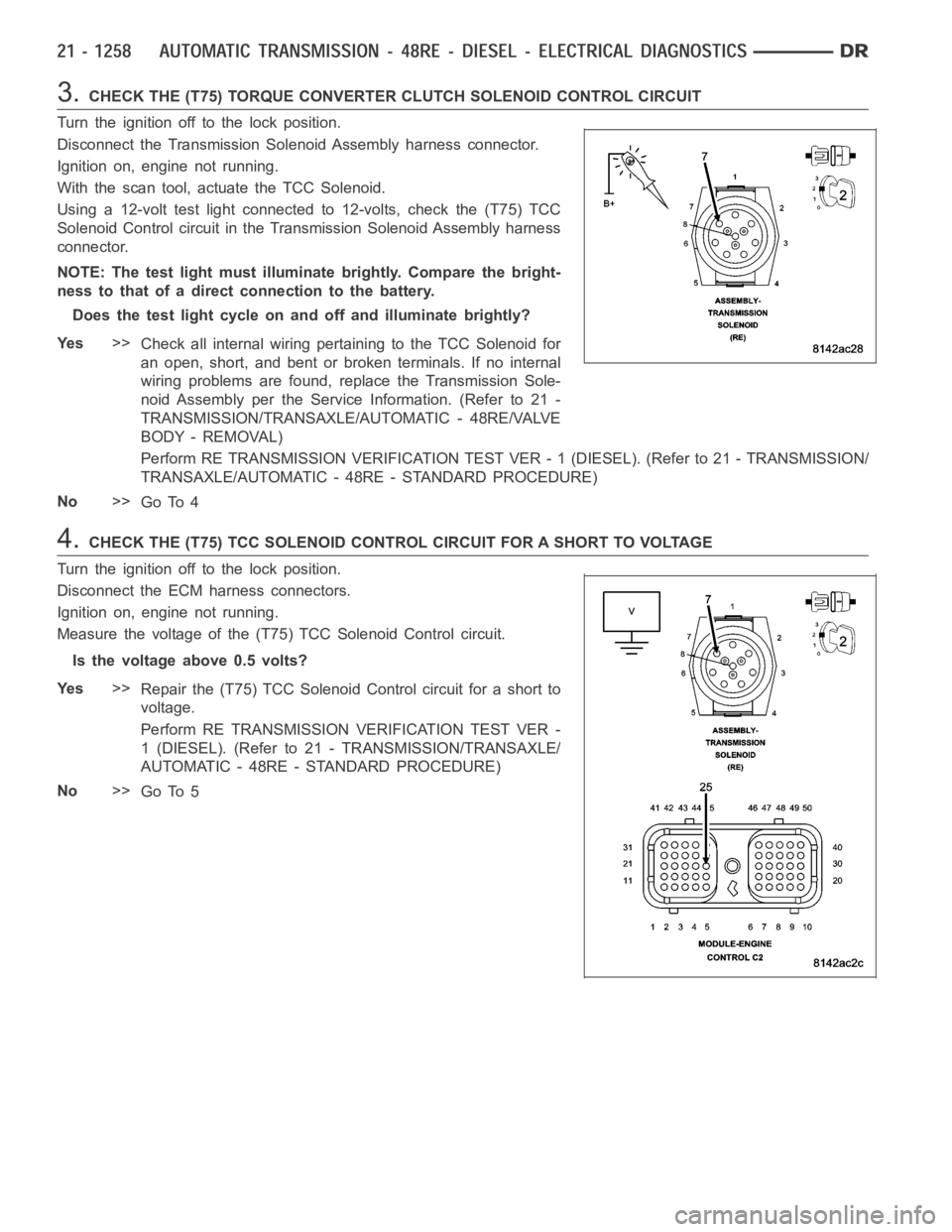
3.CHECK THE (T75) TORQUE CONVERTER CLUTCH SOLENOID CONTROL CIRCUIT
Turn the ignition off to the lock position.
Disconnect the Transmission Solenoid Assembly harness connector.
Ignition on, engine not running.
With the scan tool, actuate the TCC Solenoid.
Using a 12-volt test light connected to 12-volts, check the (T75) TCC
Solenoid Control circuit in the Transmission Solenoid Assembly harness
connector.
NOTE: The test light must illuminate brightly. Compare the bright-
ness to that of a direct connection to the battery.
Does the test light cycle on and off and illuminate brightly?
Ye s>>
Check all internal wiring pertaining to the TCC Solenoid for
an open, short, and bent or broken terminals. If no internal
wiring problems are found, replace the Transmission Sole-
noid Assembly per the Service Information. (Refer to 21 -
TRANSMISSION/TRANSAXLE/AUTOMATIC - 48RE/VALVE
BODY - REMOVAL)
Perform RE TRANSMISSION VERIFICATION TEST VER - 1 (DIESEL). (Refer to 21 - TRANSMISSION/
TRANSAXLE/AUTOMATIC - 48RE - STANDARD PROCEDURE)
No>>
Go To 4
4.CHECK THE (T75) TCC SOLENOID CONTROL CIRCUIT FOR A SHORT TO VOLTAGE
Turn the ignition off to the lock position.
Disconnect the ECM harness connectors.
Ignition on, engine not running.
Measure the voltage of the (T75) TCC Solenoid Control circuit.
Is the voltage above 0.5 volts?
Ye s>>
Repair the (T75) TCC Solenoid Control circuit for a short to
voltage.
Perform RE TRANSMISSION VERIFICATION TEST VER -
1 (DIESEL). (Refer to 21 - TRANSMISSION/TRANSAXLE/
AUTOMATIC - 48RE - STANDARD PROCEDURE)
No>>
Go To 5
Page 3780 of 5267
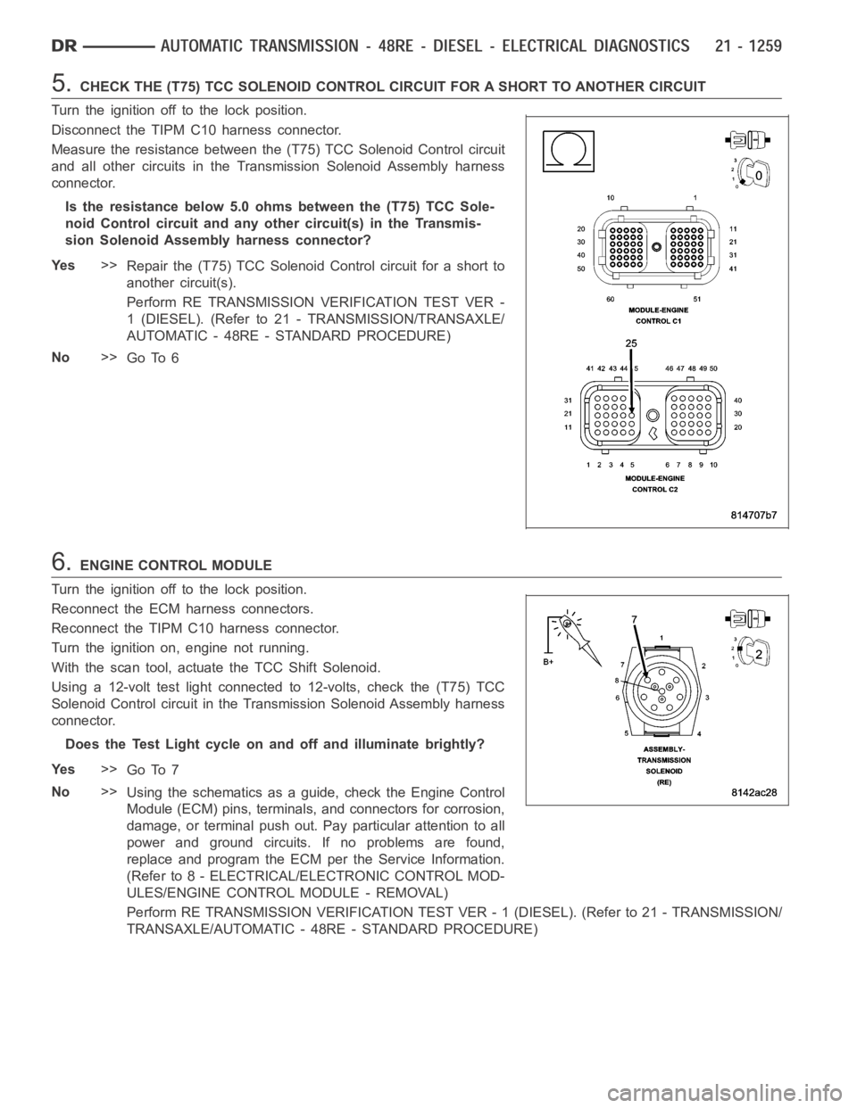
5.CHECK THE (T75) TCC SOLENOID CONTROL CIRCUIT FOR A SHORT TO ANOTHER CIRCUIT
Turn the ignition off to the lock position.
Disconnect the TIPM C10 harness connector.
Measure the resistance between the (T75) TCC Solenoid Control circuit
and all other circuits in the Transmission Solenoid Assembly harness
connector.
Is the resistance below 5.0 ohms between the (T75) TCC Sole-
noid Control circuit and any other circuit(s) in the Transmis-
sion Solenoid Assembly harness connector?
Ye s>>
Repair the (T75) TCC Solenoid Control circuit for a short to
another circuit(s).
Perform RE TRANSMISSION VERIFICATION TEST VER -
1 (DIESEL). (Refer to 21 - TRANSMISSION/TRANSAXLE/
AUTOMATIC - 48RE - STANDARD PROCEDURE)
No>>
Go To 6
6.ENGINE CONTROL MODULE
Turn the ignition off to the lock position.
Reconnect the ECM harness connectors.
Reconnect the TIPM C10 harness connector.
Turn the ignition on, engine not running.
With the scan tool, actuate the TCC Shift Solenoid.
Using a 12-volt test light connected to 12-volts, check the (T75) TCC
Solenoid Control circuit in the Transmission Solenoid Assembly harness
connector.
Does the Test Light cycle on and off and illuminate brightly?
Ye s>>
Go To 7
No>>
Using the schematics as a guide, check the Engine Control
Module (ECM) pins, terminals, and connectors for corrosion,
damage, or terminal push out. Pay particular attention to all
power and ground circuits. If no problems are found,
replace and program the ECM per the Service Information.
(Refer to 8 - ELECTRICAL/ELECTRONIC CONTROL MOD-
ULES/ENGINE CONTROL MODULE - REMOVAL)
Perform RE TRANSMISSION VERIFICATION TEST VER - 1 (DIESEL). (Refer to 21 - TRANSMISSION/
TRANSAXLE/AUTOMATIC - 48RE - STANDARD PROCEDURE)
Page 3783 of 5267
Theory of Operation
The tow/haul overdrive OFF (control) switch is located in the shift lever arm. The switch is a momentary contact
device that signals the ECM/PCM to toggle current status of the overdrive function. At ignition on, overdrive oper-
ation is allowed. Pressing the Tow/Haul Overdrive Off switch once causes the Tow/haul Overdrive OFF mode to be
entered and the Tow/Haul lamp to be illuminated. Pressing the switch a second time causes normal overdrive oper-
ationtoberestoredandtheTow/haullamptobeturnedoff.TheTow/haulOverdrive OFF mode defaults to ON after
the ignition switch is cycled OFF and ON. The normal position for the control switch is the ON position. The switch
must be in this position to energize the solenoid and allow a 3-4 upshift. The control switch indicator light illuminates
only when the Tow/haul Overdrive Off switch is turned to the OFF position, or when illuminated by the transmission
control module.
Possible Causes
TOW/HAUL OVERDRIVE OFF SWITCH SENSE CIRCUIT SHORT TO GROUND
TOW/HAUL OVERDRIVE OFF SWITCH
ENGINE CONTROL MODULE
Always perform the Pre-Diagnostic Troubleshooting procedure before proceeding. (Refer to 8 - ELECTRI-
CAL/ELECTRONIC CONTROL MODULES/TRANSMISSION CONTROL MODULE - DIAGNOSIS AND TESTING)
Diagnostic Test
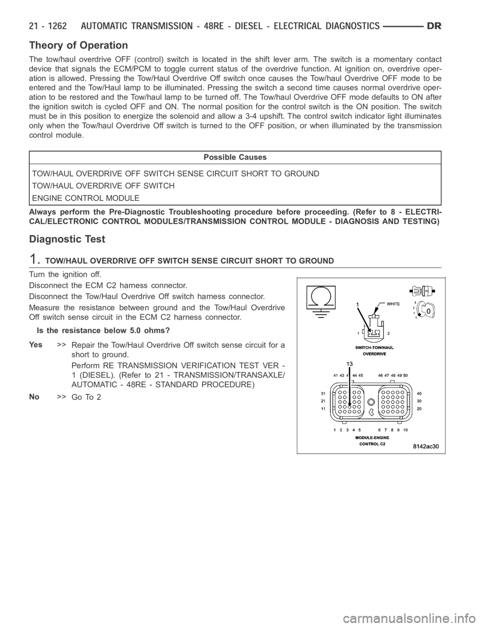
1.TOW/HAUL OVERDRIVE OFF SWITCH SENSE CIRCUIT SHORT TO GROUND
Turn the ignition off.
Disconnect the ECM C2 harness connector.
Disconnect the Tow/Haul OverdriveOff switch harness connector.
Measure the resistance between ground and the Tow/Haul Overdrive
Off switch sense circuit in the ECM C2 harness connector.
Is the resistance below 5.0 ohms?
Ye s>>
Repair the Tow/Haul Overdrive Off switch sense circuit for a
short to ground.
Perform RE TRANSMISSION VERIFICATION TEST VER -
1 (DIESEL). (Refer to 21 - TRANSMISSION/TRANSAXLE/
AUTOMATIC - 48RE - STANDARD PROCEDURE)
No>>
Go To 2
Page 3866 of 5267
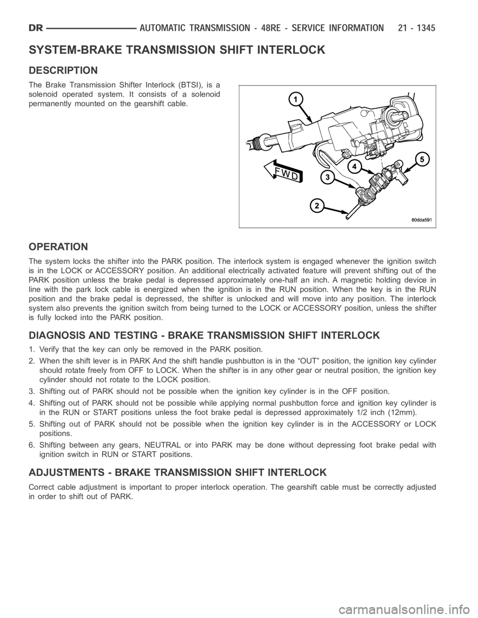
SYSTEM-BRAKE TRANSMISSION SHIFT INTERLOCK
DESCRIPTION
The Brake Transmission Shifter Interlock (BTSI), is a
solenoid operated system. It consists of a solenoid
permanently mounted on the gearshift cable.
OPERATION
The system locks the shifter into the PARK position. The interlock system is engaged whenever the ignition switch
is in the LOCK or ACCESSORY position. An additional electrically activated feature will prevent shifting out of the
PARK position unless the brake pedal is depressed approximately one-halfan inch. A magnetic holding device in
line with the park lock cable is energized when the ignition is in the RUN position. When the key is in the RUN
position and the brake pedal is depressed, the shifter is unlocked and willmove into any position. The interlock
system also prevents the ignition switch from being turned to the LOCK or ACCESSORY position, unless the shifter
is fully locked into the PARK position.
DIAGNOSIS AND TESTING - BRAKE TRANSMISSION SHIFT INTERLOCK
1. Verify that the key can only be removed in the PARK position.
2. When the shift lever is in PARK And the shift handle pushbutton is in the “OUT” position, the ignition key cylinder
should rotate freely from OFF to LOCK. When the shifter is in any other gear or neutral position, the ignition key
cylinder should not rotate to the LOCK position.
3. Shifting out of PARK should not be possible when the ignition key cylinder is in the OFF position.
4. Shifting out of PARK should not be possible while applying normal pushbutton force and ignition key cylinder is
in the RUN or START positions unless the foot brake pedal is depressed approximately 1/2 inch (12mm).
5. Shifting out of PARK should not be possible when the ignition key cylinderisintheACCESSORYorLOCK
positions.
6. Shifting between any gears, NEUTRAL or into PARK may be done without depressing foot brake pedal with
ignition switch in RUN or START positions.
ADJUSTMENTS - BRAKE TRANSMISSION SHIFT INTERLOCK
Correct cable adjustment is important to proper interlock operation. Thegearshift cable must be correctly adjusted
in order to shift out of PARK.
Page 3867 of 5267
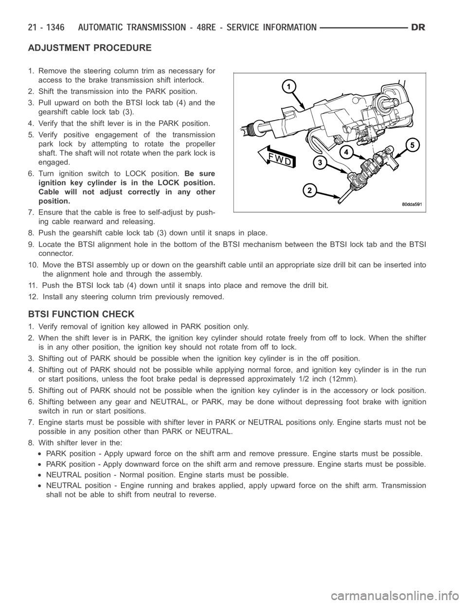
ADJUSTMENT PROCEDURE
1. Remove the steering column trim as necessary for
access to the brake transmission shift interlock.
2. Shift the transmission into the PARK position.
3. Pull upward on both the BTSI lock tab (4) and the
gearshift cable lock tab (3).
4. Verify that the shift lever is in the PARK position.
5. Verify positive engagement of the transmission
park lock by attempting to rotate the propeller
shaft. The shaft will not rotate when the park lock is
engaged.
6. Turn ignition switch to LOCK position.Be sure
ignition key cylinder is in the LOCK position.
Cable will not adjust correctly in any other
position.
7. Ensure that the cable is free to self-adjust by push-
ing cable rearward and releasing.
8. Push the gearshift cable lock tab (3) down until it snaps in place.
9. Locate the BTSI alignment hole in the bottom of the BTSI mechanism betweentheBTSIlocktabandtheBTSI
connector.
10. Move the BTSI assembly up or down on the gearshift cable until an appropriate size drill bit can be inserted into
the alignment hole and through the assembly.
11. Push the BTSI lock tab (4) down until it snaps into place and remove the drill bit.
12. Install any steering column trim previously removed.
BTSI FUNCTION CHECK
1. Verify removal of ignition key allowed in PARK position only.
2. When the shift lever is in PARK, the ignition key cylinder should rotate freely from off to lock. When the shifter
is in any other position, the ignition key should not rotate from off to lock.
3. Shifting out of PARK should be possible when the ignition key cylinder isin the off position.
4. Shifting out of PARK should not be possible while applying normal force,and ignition key cylinder is in the run
or start positions, unless the foot brake pedal is depressed approximately1/2inch(12mm).
5. Shifting out of PARK should not be possible when the ignition key cylinder is in the accessory or lock position.
6. Shifting between any gear and NEUTRAL, or PARK, may be done without depressing foot brake with ignition
switch in run or start positions.
7. Engine starts must be possible with shifter lever in PARK or NEUTRAL positions only. Engine starts must not be
possible in any position other than PARK or NEUTRAL.
8. With shifter lever in the:
PARK position - Apply upward force on the shift arm and remove pressure. Enginestartsmustbepossible.
PARK position - Apply downward force on the shift arm and remove pressure. Engine starts must be possible.
NEUTRAL position - Normal position. Engine starts must be possible.
NEUTRAL position - Engine running and brakes applied, apply upward force on the shift arm. Transmission
shall not be able to shift from neutral to reverse.
Page 3949 of 5267
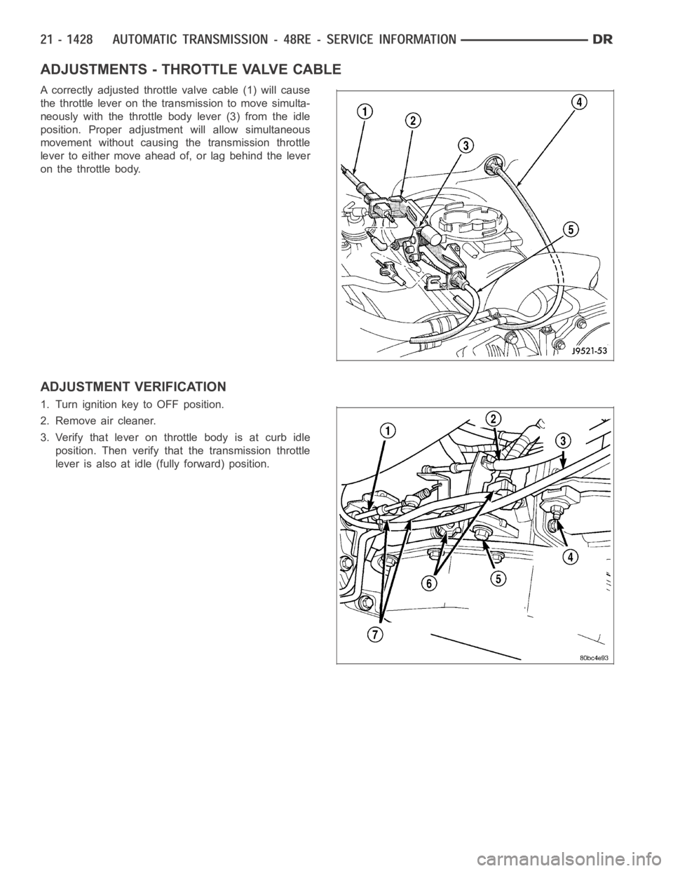
ADJUSTMENTS - THROTTLE VALVE CABLE
A correctly adjusted throttle valve cable (1) will cause
the throttle lever on the transmission to move simulta-
neously with the throttle body lever (3) from the idle
position. Proper adjustment will allow simultaneous
movement without causing the transmission throttle
lever to either move ahead of, or lag behind the lever
on the throttle body.
ADJUSTMENT VERIFICATION
1. Turn ignition key to OFF position.
2. Remove air cleaner.
3. Verify that lever on throttle body is at curb idle
position. Then verify that the transmission throttle
lever is also at idle (fully forward) position.
Page 3950 of 5267
4. Slide cable off attachment stud on throttle body
lever.
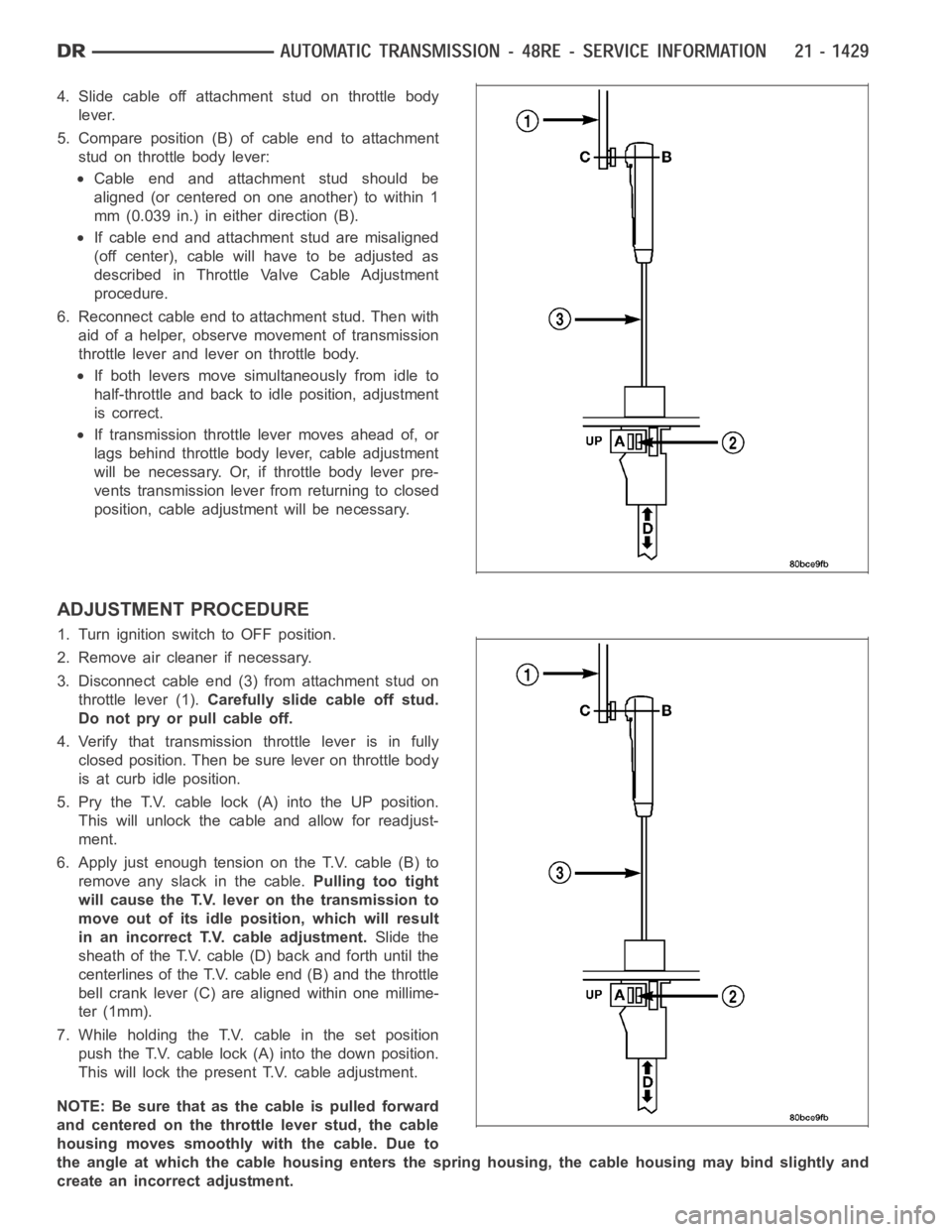
5. Compare position (B) of cable end to attachment
stud on throttle body lever:
Cable end and attachment stud should be
aligned (or centered on one another) to within 1
mm (0.039 in.) in either direction (B).
If cable end and attachment stud are misaligned
(off center), cable will have to be adjusted as
described in Throttle Valve Cable Adjustment
procedure.
6. Reconnect cable end to attachment stud. Then with
aid of a helper, observe movement of transmission
throttle lever and lever on throttle body.
If both levers move simultaneously from idle to
half-throttle and back to idle position, adjustment
is correct.
If transmission throttle lever moves ahead of, or
lags behind throttle body lever, cable adjustment
will be necessary. Or, if throttle body lever pre-
vents transmission lever from returning to closed
position, cable adjustment will be necessary.
ADJUSTMENT PROCEDURE
1. Turn ignition switch to OFF position.
2. Remove air cleaner if necessary.
3. Disconnect cable end (3) from attachment stud on
throttle lever (1).Carefully slide cable off stud.
Do not pry or pull cable off.
4. Verify that transmission throttle lever is in fully
closed position. Then be sure lever on throttle body
is at curb idle position.
5. Pry the T.V. cable lock (A) into the UP position.
This will unlock the cable and allow for readjust-
ment.
6. Apply just enough tension on the T.V. cable (B) to
remove any slack in the cable.Pulling too tight
will cause the T.V. lever on the transmission to
move out of its idle position, which will result
in an incorrect T.V. cable adjustment.Slide the
sheath of the T.V. cable (D) back and forth until the
centerlines of the T.V. cable end (B) and the throttle
bell crank lever (C) are aligned within one millime-
ter (1mm).
7. While holding the T.V. cable in the set position
push the T.V. cable lock (A) into the down position.
This will lock the present T.V. cable adjustment.
NOTE:Besurethatasthecableispulledforward
and centered on the throttle lever stud, the cable
housing moves smoothly with the cable. Due to
the angle at which the cable housing enters the spring housing, the cable housing may bind slightly and
create an incorrect adjustment.