Page 3961 of 5267
SWITCH-TOW/HAUL OVERDRIVE
DESCRIPTION
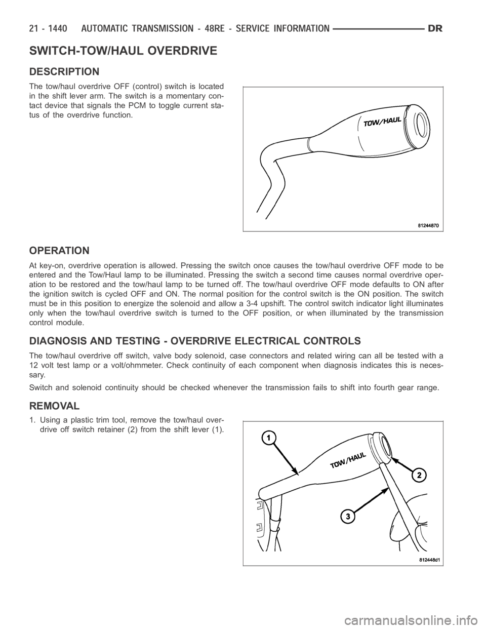
The tow/haul overdrive OFF (control) switch is located
in the shift lever arm. The switch is a momentary con-
tact device that signals the PCM to toggle current sta-
tus of the overdrive function.
OPERATION
At key-on, overdrive operation is allowed. Pressing the switch once causes the tow/haul overdrive OFF mode to be
entered and the Tow/Haul lamp to be illuminated. Pressing the switch a second time causes normal overdrive oper-
ationtoberestoredandthetow/haullamptobeturnedoff.Thetow/hauloverdrive OFF mode defaults to ON after
the ignition switch is cycled OFF and ON. The normal position for the control switch is the ON position. The switch
must be in this position to energize the solenoid and allow a 3-4 upshift. The control switch indicator light illuminates
only when the tow/haul overdrive switch is turned to the OFF position, or when illuminated by the transmission
control module.
DIAGNOSIS AND TESTING - OVERDRIVE ELECTRICAL CONTROLS
The tow/haul overdrive off switch, valve body solenoid, case connectors and related wiring can all be tested with a
12 volt test lamp or a volt/ohmmeter. Check continuity of each component when diagnosis indicates this is neces-
sary.
Switch and solenoid continuity shouldbe checked whenever the transmission fails to shift into fourth gear range.
REMOVAL
1. Using a plastic trim tool, remove the tow/haul over-
drive off switch retainer (2) from the shift lever (1).
Page 3963 of 5267

SENSOR-TRANSMISSION RANGE
DESCRIPTION
The Transmission Range Sensor (TRS) has 3 primary
functions:
Provide a PARK/NEUTRAL start signal to the
engine controller and the starter relay.
Turn the Back-up lamps on when the transmis-
sion is in REVERSE and the engine (ignition) is
on.
Provide a transmission range signal to the instru-
ment cluster.
The sensor is mounted in the transmission housing
near the valve body, just above the pan rail. It’s in the
same position as the Park/Neutral switch on other
transmissions. The TRS contacts a cammed surface
on the manual valve lever. The cammed surface trans-
lates the rotational motion of the manual lever into the
linear motion of the sensor. The cammed surface on
the manual lever is comprised of two parts controlling
the TRS signal: The insulator portion contacts the
switch poppet when the manual lever is not in PARK
or NEUTRAL. The manual lever itself contacts the
poppet when the lever is in PARK or NEUTRAL; pro-
viding a ground for the signal from the starter relay
and the appropriate engine controller.
OPERATION
As the switch moves through its linear motion contacts
slide across a circuit board which changes the resis-
tance between the range sensing pins of the switch. A
power supply on the instrument cluster provides a reg-
ulated voltage signal to the switch. The return signal is
decoded by the cluster, which then controls the
PRNDL display to correspond with the correct trans-
mission range. A bus message of transmission range
Page 3964 of 5267
is also sent by the cluster. In REVERSE range a second contact set closes thecircuit providing power to the
reverse lamps.
Indicated Gear Position Transmission
StatusColumn Shifter
Position
Mechanical State Electronic Display
(Ignition Unlocked)Electronic Display
(Ignition On)
P P P Vehicle is in PARK
with the pawl
engaged.In the PARK gate.
R The PARK pawl is
disengaged and the
vehicle is free to
roll, but REVERSE
is not engaged.Between the PARK
and REVERSE
gates.
R R R The transmission is
hydraulically in
REVERSE.In the REVERSE
gate.
N The transmission is
transitioning
between REVERSE
and NEUTRAL.Between the
REVERSE and
NEUTRAL gates.
N N N The vehicle is in
NEUTRAL.In the NEUTRAL
gate.
N The transmission is
transitioning
between NEUTRAL
and DRIVE, but is
not in DRIVE.Between the
NEUTRAL and
DRIVE gates.
D D D The transmission is
hydraulically in
DRIVE.In the DRIVE gate,
2 2 2 The transmission is
hydraulically in
Manual SECOND.In the SECOND
gate.
1 1 1 The transmission is
hydraulically in
Manual FIRST.In the FIRST gate.
DIAGNOSIS AND TESTING - TRANSMISSION RANGE SENSOR (TRS)
NOTE: For all circuit identification in the following steps, Refer to the appropriate Wiring Information.
1. Raise vehicle on suitable hoist.
2. Disconnect the vehicle’s shift cable from the manual lever.
3. With the manual lever in the PARK position (the PARK position is with the manual lever moved to the full rear-
ward position), measure the resistance between the Park/Neutral PositionSensepinoftheTRSandthetrans-
mission case. The resistance should be less than 5 ohms.
4. With the manual lever in the NEUTRAL position (the NEUTRAL position is with the manual lever moved two
detents forward of the full rearward position), measure the resistance between the Park/Neutral Position Sense
pin of the TRS and the transmission case. The resistance should be less than5ohms.
5. If the resistance is greater than 5 ohms in either of the previous steps, check for a dirty contact between the tip
of the TRS rod and the valve body manual lever. If the contact is OK, replace the TRS.
6. With the manual lever in the REVERSE position (the REVERSE position is with the manual lever moved one
detent forward of the full rearward position), measure the resistance between the Fused Ignition Switch Output
Page 4023 of 5267
When Monitored:
With the ignition on.
Set Condition:
Transfer Case Range Select Switch voltage less than 0.1568 volts for 5 seconds
Possible Causes
(K77) 5 VOLT SELECTOR SWITCH SUPPLY CIRCUIT OPEN
(K77) 5 VOLT SELECTOR SWITCH SUPPLY CIRCUIT SHORTED TO GROUND
(K977) MODE SELECT CIRCUIT OPEN
(K977) MODE SELECT CIRCUIT SHORT TO GROUND
TRANSFER CASE SELECTOR SWITCH
INSTRUMENT CLUSTER
Diagnostic Test
1.TRANSFER CASE SWITCH VOLTAGE LESS THAN 0.2 VOLTS
Ignition on, engine not running.
With the scan tool under Instrument Cluster, read the Transfer Case Switchvoltage.
Is the voltage less than 0.2 volts?
Ye s>>
Go To 2
No>>
Go To 8
2.(K77) 5 VOLT SELECTOR SWITCH SUPPLY CIRCUIT VOLTAGE LESS THAN 0.2 VOLTS
Turn the ignition off to the lock position.
Disconnect the Transfer Case Selector Switch harness connector.
Ignition on, engine not running.
Measure the voltage of the (K77) 5 Volt Selector Switch Supply circuit.
Is the voltage less than 0.2 volts?
Ye s>>
Go To 3
No>>
Go To 5
Page 4024 of 5267
3.(K77) 5 VOLT SELECTOR SWITCH SUPPLY CIRCUIT OPEN
Turn the ignition off to the lock position.
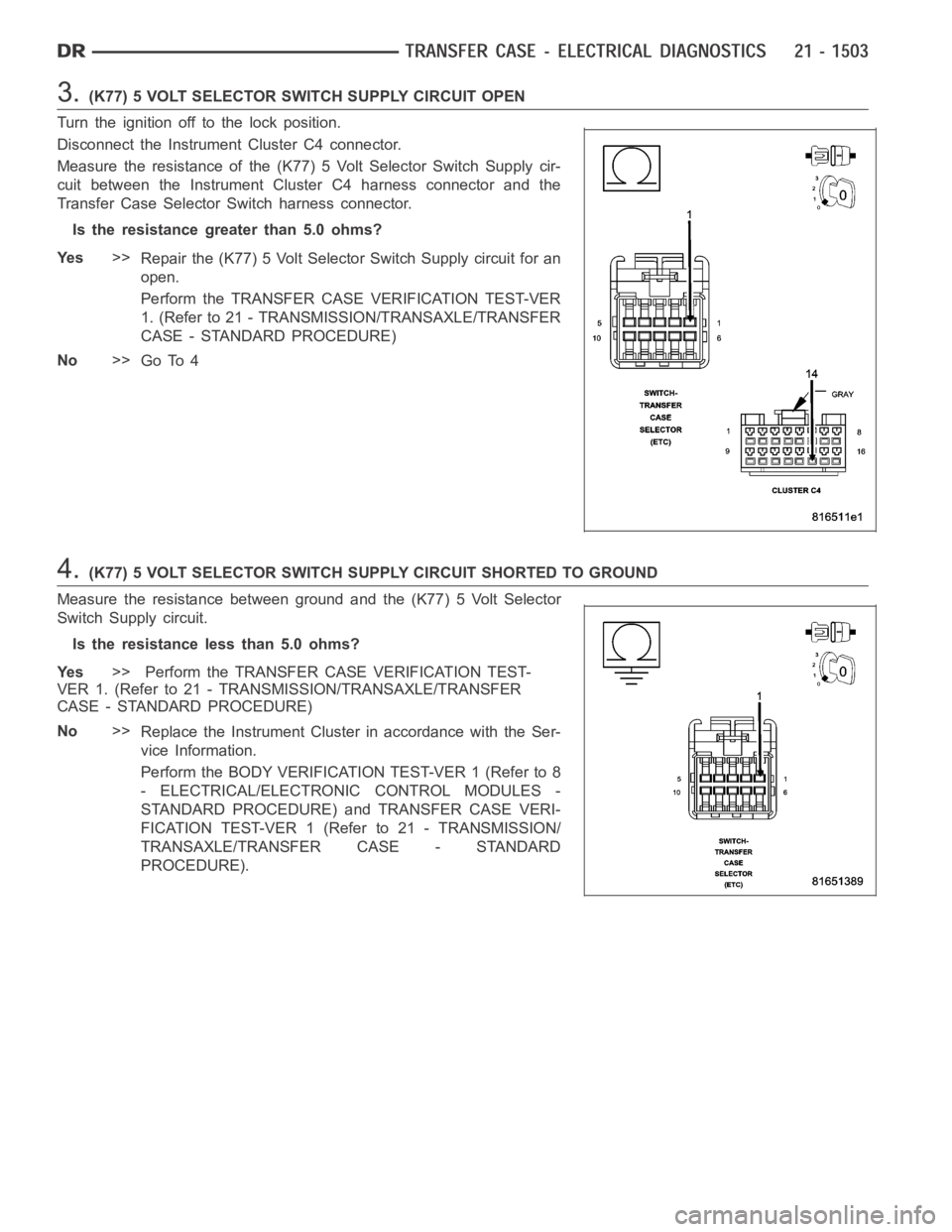
Disconnect the Instrument Cluster C4 connector.
Measure the resistance of the (K77) 5 Volt Selector Switch Supply cir-
cuit between the Instrument Cluster C4 harness connector and the
Transfer Case Selector Switch harness connector.
Is the resistance greater than 5.0 ohms?
Ye s>>
Repair the (K77) 5 Volt Selector Switch Supply circuit for an
open.
Perform the TRANSFER CASE VERIFICATION TEST-VER
1. (Refer to 21 - TRANSMISSION/TRANSAXLE/TRANSFER
CASE - STANDARD PROCEDURE)
No>>
Go To 4
4.(K77) 5 VOLT SELECTOR SWITCH SUPPLY CIRCUIT SHORTED TO GROUND
Measure the resistance between ground and the (K77) 5 Volt Selector
Switch Supply circuit.
Is the resistance less than 5.0 ohms?
Ye s>> Perform the TRANSFER CASE VERIFICATION TEST-
VER 1. (Refer to 21 - TRANSMISSION/TRANSAXLE/TRANSFER
CASE - STANDARD PROCEDURE)
No>>
Replace the Instrument Cluster in accordance with the Ser-
vice Information.
Perform the BODY VERIFICATION TEST-VER 1 (Refer to 8
- ELECTRICAL/ELECTRONIC CONTROL MODULES -
STANDARD PROCEDURE) and TRANSFER CASE VERI-
FICATION TEST-VER 1 (Refer to 21 - TRANSMISSION/
TRANSAXLE/TRANSFER CASE - STANDARD
PROCEDURE).
Page 4025 of 5267
5.TRANSFER CASE SELECTOR SWITCH
Turn the ignition off to the lock position.
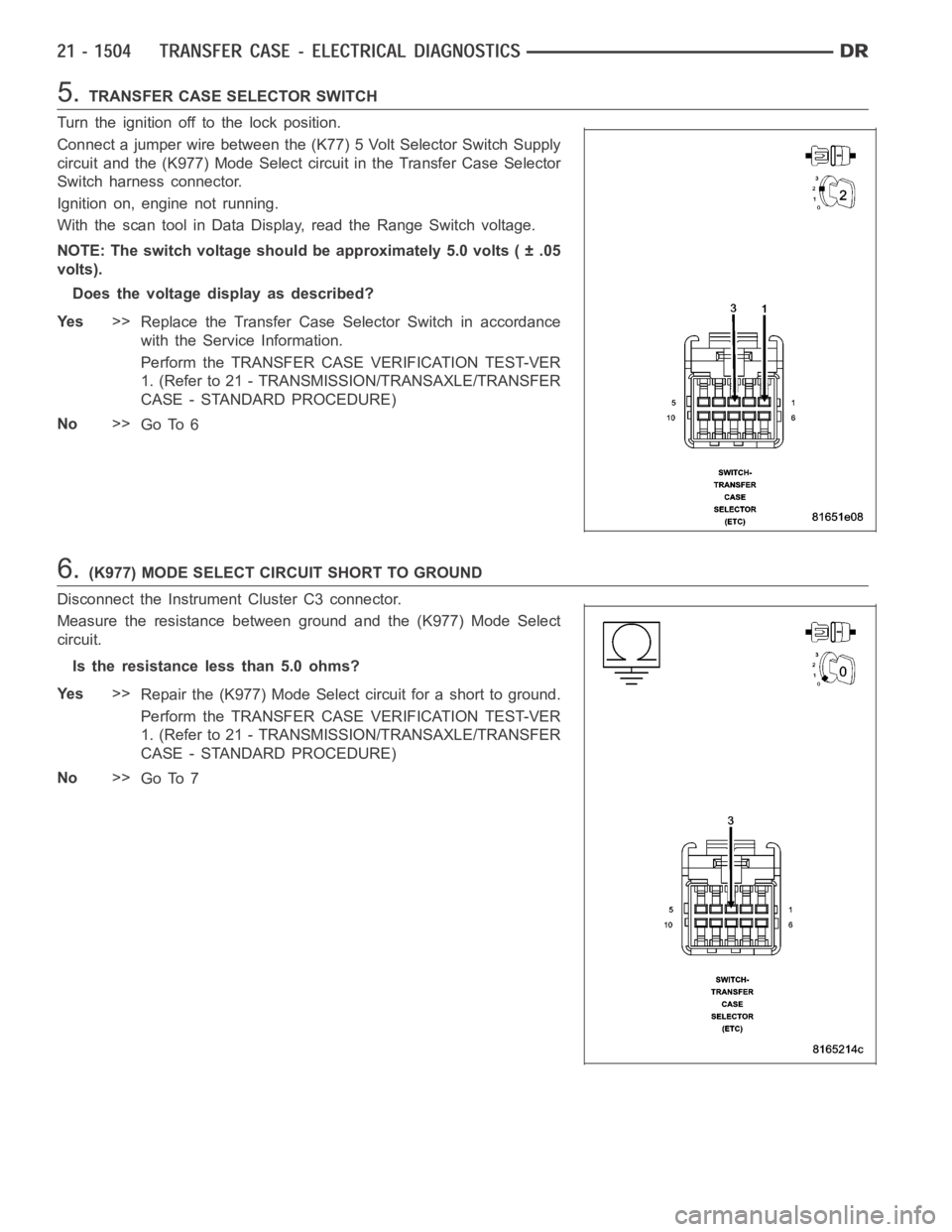
Connect a jumper wire between the (K77) 5 Volt Selector Switch Supply
circuit and the (K977) Mode Select circuit in the Transfer Case Selector
Switch harness connector.
Ignition on, engine not running.
With the scan tool in Data Display, read the Range Switch voltage.
NOTE: The switch voltage should be approximately 5.0 volts ( ± .05
volts).
Does the voltage display as described?
Ye s>>
Replace the Transfer Case Selector Switch in accordance
with the Service Information.
Perform the TRANSFER CASE VERIFICATION TEST-VER
1. (Refer to 21 - TRANSMISSION/TRANSAXLE/TRANSFER
CASE - STANDARD PROCEDURE)
No>>
Go To 6
6.(K977) MODE SELECT CIRCUIT SHORT TO GROUND
Disconnect the Instrument Cluster C3 connector.
Measure the resistance between ground and the (K977) Mode Select
circuit.
Is the resistance less than 5.0 ohms?
Ye s>>
Repair the (K977) Mode Select circuit for a short to ground.
Perform the TRANSFER CASE VERIFICATION TEST-VER
1. (Refer to 21 - TRANSMISSION/TRANSAXLE/TRANSFER
CASE - STANDARD PROCEDURE)
No>>
Go To 7
Page 4028 of 5267
When Monitored:
With the ignition on.
Set Condition:
Transfer Case Range Select Switch voltage greater than 4.86 volts for 5 seconds
Possible Causes
(K77) 5 VOLT SELECTOR SWITCH SUPPLY CIRCUIT SHORTED TO VOLTAGE
(K977) MODE SELECT CIRCUIT SHORTED TO VOLTAGE
(K977) MODE SELECT CIRCUIT OPEN
(Z905) TRANSFER CASE SELECTOR SWITCH GROUND CIRCUIT OPEN
TRANSFER CASE SELECTOR SWITCH
INSTRUMENT CLUSTER
Diagnostic Test
1.TCASE SWITCH VOLTAGE ABOVE 4.8 VOLTS
Ignition on, engine not running.
With the scan tool under Instrument Cluster, read the Transfer Case Switchvoltage.
Is the volage above 4.8 volts?
Ye s>>
Go To 2
No>>
Go to 8
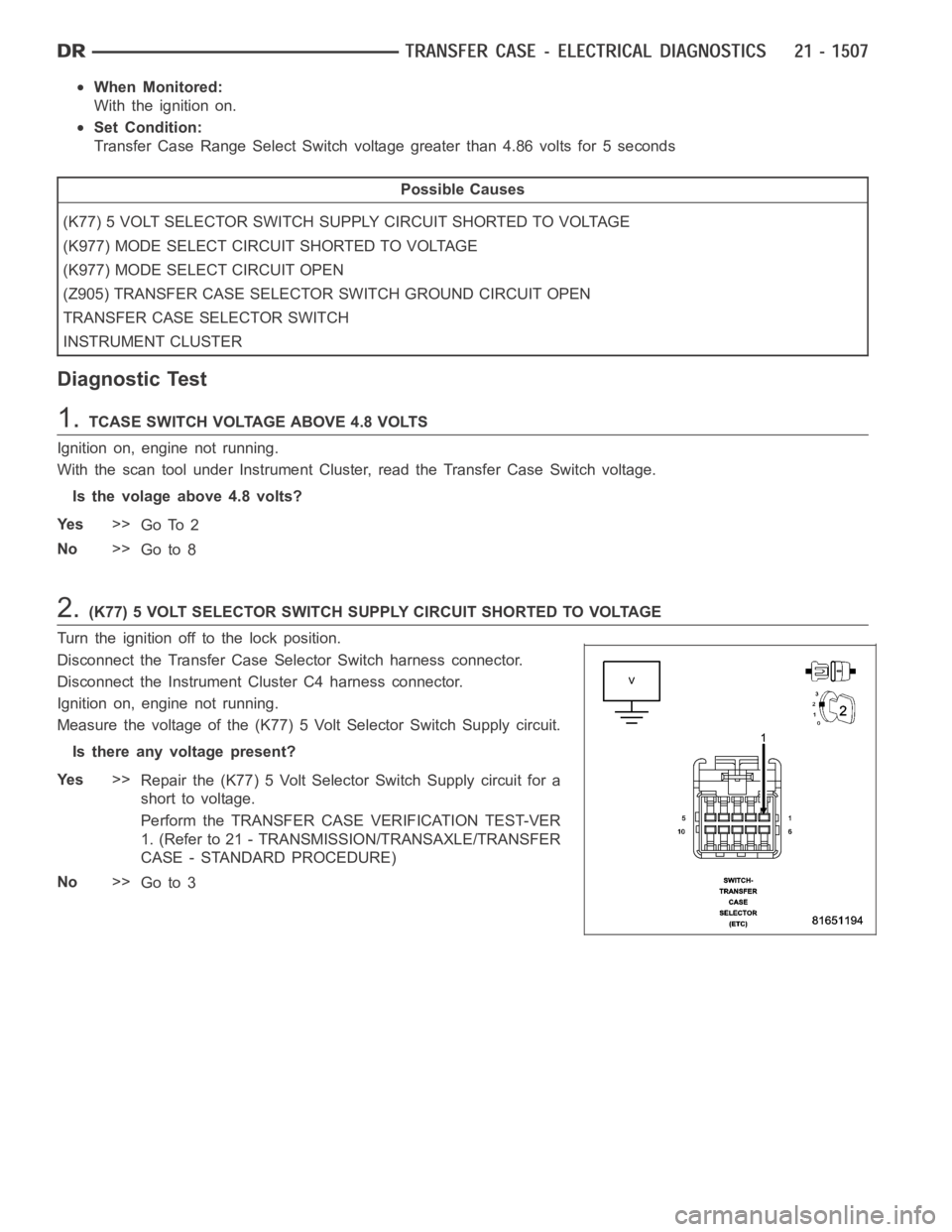
2.(K77) 5 VOLT SELECTOR SWITCH SUPPLY CIRCUIT SHORTED TO VOLTAGE
Turn the ignition off to the lock position.
Disconnect the Transfer Case Selector Switch harness connector.
Disconnect the Instrument Cluster C4 harness connector.
Ignition on, engine not running.
Measure the voltage of the (K77) 5 Volt Selector Switch Supply circuit.
Is there any voltage present?
Ye s>>
Repair the (K77) 5 Volt Selector Switch Supply circuit for a
short to voltage.
Perform the TRANSFER CASE VERIFICATION TEST-VER
1. (Refer to 21 - TRANSMISSION/TRANSAXLE/TRANSFER
CASE - STANDARD PROCEDURE)
No>>
Go to 3
Page 4029 of 5267
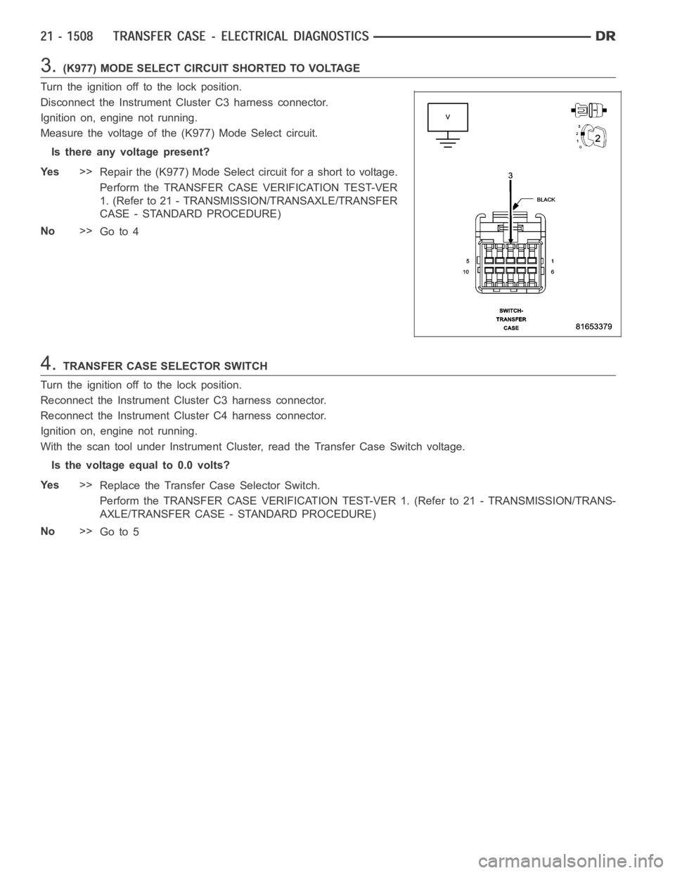
3.(K977) MODE SELECT CIRCUIT SHORTED TO VOLTAGE
Turn the ignition off to the lock position.
Disconnect the Instrument Cluster C3 harness connector.
Ignition on, engine not running.
Measure the voltage of the (K977) Mode Select circuit.
Is there any voltage present?
Ye s>>
Repair the (K977) Mode Select circuit for a short to voltage.
Perform the TRANSFER CASE VERIFICATION TEST-VER
1. (Refer to 21 - TRANSMISSION/TRANSAXLE/TRANSFER
CASE - STANDARD PROCEDURE)
No>>
Go to 4
4.TRANSFER CASE SELECTOR SWITCH
Turn the ignition off to the lock position.
Reconnect the Instrument Cluster C3 harness connector.
Reconnect the Instrument Cluster C4 harness connector.
Ignition on, engine not running.
With the scan tool under Instrument Cluster, read the Transfer Case Switchvoltage.
Is the voltage equal to 0.0 volts?
Ye s>>
Replace the Transfer Case Selector Switch.
Perform the TRANSFER CASE VERIFICATION TEST-VER 1. (Refer to 21 - TRANSMISSION/TRANS-
AXLE/TRANSFER CASE - STANDARD PROCEDURE)
No>>
Go to 5