2006 DODGE RAM SRT-10 oil level
[x] Cancel search: oil levelPage 3809 of 5267
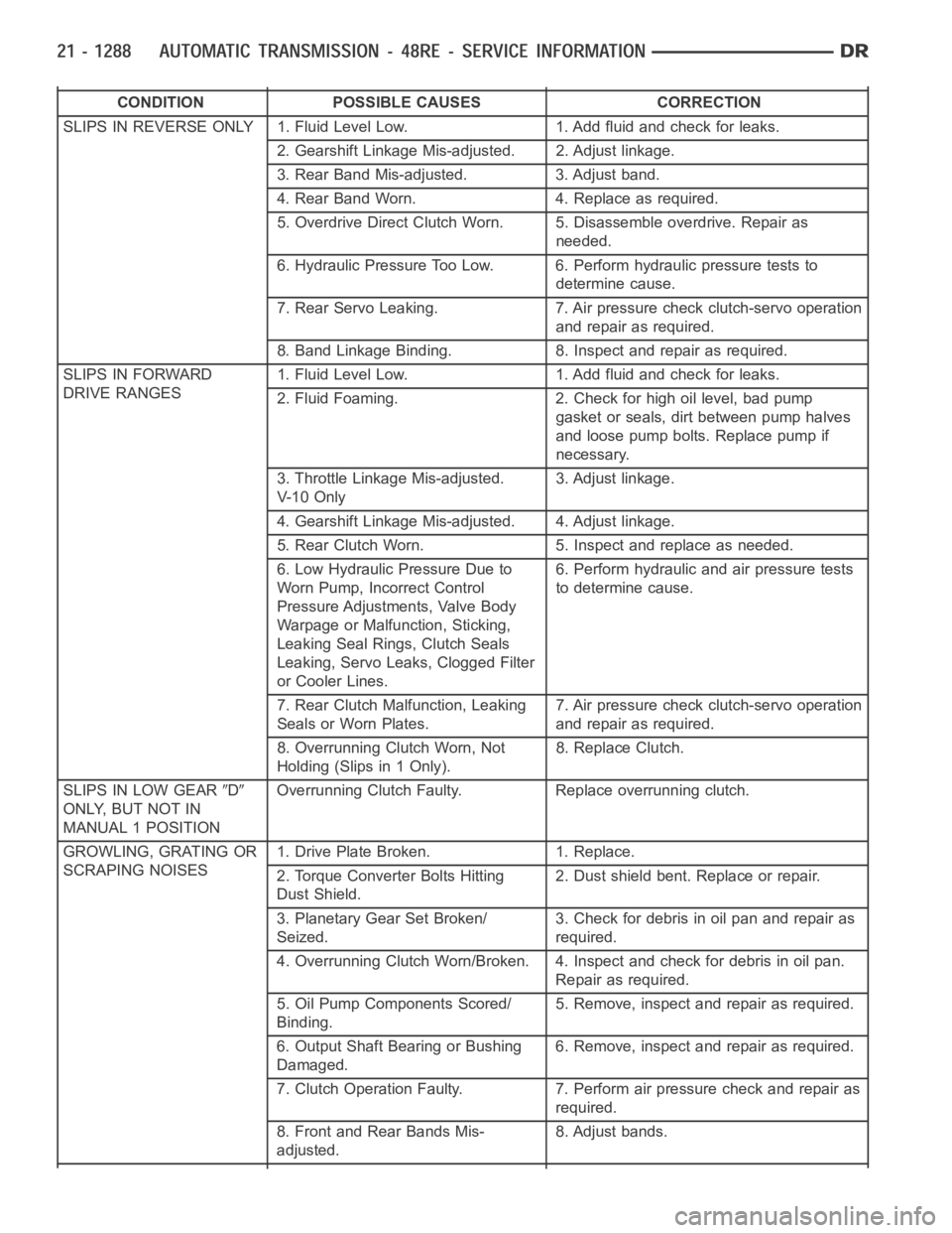
CONDITION POSSIBLE CAUSES CORRECTION
SLIPS IN REVERSE ONLY 1. Fluid Level Low. 1. Add fluid and check for leaks.
2. Gearshift Linkage Mis-adjusted. 2. Adjust linkage.
3. Rear Band Mis-adjusted. 3. Adjust band.
4. Rear Band Worn. 4. Replace as required.
5. Overdrive Direct Clutch Worn. 5. Disassemble overdrive. Repair as
needed.
6. Hydraulic Pressure Too Low. 6. Perform hydraulic pressure tests to
determine cause.
7. Rear Servo Leaking. 7. Air pressure check clutch-servo operation
and repair as required.
8. Band Linkage Binding. 8. Inspect and repair as required.
SLIPS IN FORWARD
DRIVE RANGES1. Fluid Level Low. 1. Add fluid and check for leaks.
2. Fluid Foaming. 2. Check for high oil level, bad pump
gasket or seals, dirt between pump halves
and loose pump bolts. Replace pump if
necessary.
3. Throttle Linkage Mis-adjusted.
V- 1 0 O n l y3. Adjust linkage.
4. Gearshift Linkage Mis-adjusted. 4. Adjust linkage.
5. Rear Clutch Worn. 5. Inspect and replace as needed.
6. Low Hydraulic Pressure Due to
Worn Pump, Incorrect Control
Pressure Adjustments, Valve Body
Warpage or Malfunction, Sticking,
Leaking Seal Rings, Clutch Seals
Leaking, Servo Leaks, Clogged Filter
or Cooler Lines.6. Perform hydraulic and air pressure tests
to determine cause.
7. Rear Clutch Malfunction, Leaking
Seals or Worn Plates.7. Air pressure check clutch-servo operation
and repair as required.
8. Overrunning Clutch Worn, Not
Holding (Slips in 1 Only).8. Replace Clutch.
SLIPS IN LOW GEAR
D
ONLY, BUT NOT IN
MANUAL 1 POSITIONOverrunning Clutch Faulty. Replace overrunning clutch.
GROWLING, GRATING OR
SCRAPING NOISES1. Drive Plate Broken. 1. Replace.
2. Torque Converter Bolts Hitting
Dust Shield.2. Dust shield bent. Replace or repair.
3. Planetary Gear Set Broken/
Seized.3. Check for debris in oil pan and repair as
required.
4. Overrunning Clutch Worn/Broken. 4. Inspect and check for debris in oil pan.
Repair as required.
5. Oil Pump Components Scored/
Binding.5. Remove, inspect and repair as required.
6. Output Shaft Bearing or Bushing
Damaged.6. Remove, inspect and repair as required.
7. Clutch Operation Faulty. 7. Perform air pressure check and repair as
required.
8. Front and Rear Bands Mis-
adjusted.8. Adjust bands.
Page 3810 of 5267
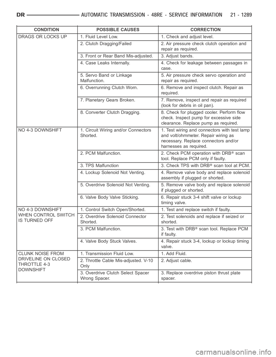
CONDITION POSSIBLE CAUSES CORRECTION
DRAGS OR LOCKS UP 1. Fluid Level Low. 1. Check and adjust level.
2. Clutch Dragging/Failed 2. Air pressure check clutch operation and
repair as required.
3. Front or Rear Band Mis-adjusted. 3. Adjust bands.
4. Case Leaks Internally. 4. Check for leakage between passages in
case.
5. Servo Band or Linkage
Malfunction.5. Air pressure check servo operation and
repair as required.
6. Overrunning Clutch Worn. 6. Remove and inspect clutch. Repair as
required.
7. Planetary Gears Broken. 7. Remove, inspect and repair as required
(look for debris in oil pan).
8. Converter Clutch Dragging. 8. Check for plugged cooler. Perform flow
check. Inspect pump for excessive side
clearance. Replace pump as required.
NO 4-3 DOWNSHIFT 1. Circuit Wiring and/or Connectors
Shorted.1. Test wiring and connectors with test lamp
and volt/ohmmeter. Repair wiring as
necessary. Replace connectors and/or
harnesses as required.
2. PCM Malfunction. 2. Check PCM operation with DRB
scan
tool. Replace PCM only if faulty.
3. TPS Malfunction 3. Check TPS with DRB
scan tool at PCM.
4. Lockup Solenoid Not Venting. 4. Remove valve body and replace solenoid
assembly if plugged or shorted.
5. Overdrive Solenoid Not Venting. 5. Remove valve body and replace solenoid
if plugged or shorted.
6. Valve Body Valve Sticking. 6. Repair stuck 3-4 shift valve or lockup
timing valve.
NO 4-3 DOWNSHIFT
WHEN CONTROL SWITCH
IS TURNED OFF1. Control Switch Open/Shorted. 1. Test and replace switch if faulty.
2. Overdrive Solenoid Connector
Shorted.2. Test solenoids and replace if seized or
shorted.
3. PCM Malfunction. 3. Test with DRB
scan tool. Replace PCM
if faulty.
4. Valve Body Stuck Valves. 4. Repair stuck 3-4, lockup or lockup timing
valve.
CLUNK NOISE FROM
DRIVELINE ON CLOSED
THROTTLE 4-3
DOWNSHIFT1. Transmission Fluid Low. 1. Add Fluid.
2. Throttle Cable Mis-adjusted. V-10
Only2. Adjust cable.
3. Overdrive Clutch Select Spacer
Wrong Spacer.3. Replace overdrive piston thrust plate
spacer.
Page 3874 of 5267
FLUID AND FILTER
DIAGNOSIS AND TESTING
EFFECTS OF INCORRECT FLUID LEVEL
Alowfluidlevelallowsthepumptotakeinairalongwiththefluid.Airinthe fluid will cause fluid pressures to be
low and develop slower than normal. If the transmission is overfilled, thegears churn the fluid into foam. This aer-
ates the fluid and causing the same conditions occurring with a low level. In either case, air bubbles cause fluid
overheating, oxidation, and varnish buildup which interferes with valveand clutch operation. Foaming also causes
fluid expansion which can result in fluid overflow from the transmission vent or fill tube. Fluid overflow can easily be
mistaken for a leak if inspection is not careful.
CAUSES OF BURNT FLUID
Burnt, discolored fluid is a result of overheating which has two primary causes.
1. A result of restricted fluid flow through the main and/or auxiliary cooler. This condition is usually the result of a
faulty or improperly installed drainback valve, a damaged oil cooler, or severe restrictions in the coolers and lines
caused by debris or kinked lines.
2. Heavy duty operation with a vehicle not properly equipped for this type of operation. Trailer towing or similar high
load operation will overheat the transmission fluid if the vehicle is improperly equipped. Such vehicles should
have an auxiliary transmission fluid cooler, a heavy duty cooling system,and the engine/axle ratio combination
needed to handle heavy loads.
FLUID CONTAMINATION
Transmission fluid contamination is generally a result of:
adding incorrect fluid
failure to clean dipstick and fill tube when checking level
engine coolant entering the fluid
internal failure that generates debris
overheat that generates sludge (fluid breakdown)
failure to replace contaminated converter after repair
The use of non-recommended fluids can result in transmission failure. Theusual results are erratic shifts, slippage,
abnormal wear and eventual failure due to fluid breakdown and sludge formation. Avoid this condition by using rec-
ommended fluids only.
The dipstick cap and fill tube should be wiped clean before checking fluid level. Dirt, grease and other foreign mate-
rial on the cap and tube could fall into the tube if not removed beforehand. Take the time to wipe the cap and tube
clean before withdrawing the dipstick.
Engine coolant in the transmission fluid is generally caused by a cooler malfunction. The only remedy is to replace
the radiator as the cooler in the radiator is not a serviceable part. If coolant has circulated through the transmission,
an overhaul is necessary.
The torque converter should also be replaced whenever a failure generatessludge and debris. This is necessary
because normal converter flushing procedures will not remove all contaminants.
STANDARD PROCEDURE
FLUID LEVEL CHECK
Low fluid level can cause a variety of conditions because it allows the pumpto take in air along with the fluid. As
in any hydraulic system, air bubbles make the fluid spongy, therefore, pressures will be low and build up slowly.
Improper filling can also raise the fluid level too high. When the transmssion has too much fluid, the geartrain
churns up foam and cause the same conditions which occur with a low fluid level.
In either case, air bubbles can cause overheating and/or fluid oxidation,and varnishing. This can interfere with nor-
mal valve, clutch, and accumulator operation. Foaming can also result in fluid escaping from the transmission vent
where it may be mistaken for a leak.
Page 3875 of 5267
After the fluid has been checked, seat the dipstick fully to seal out water and dirt.
The transmission has a dipstick to check oil level. It is located on the right side of the engine. Be sure to wipe all
dirt from dipstick handle before removing.
Fluid level is checked with the engine running at curb idle speed, the transmissioninNEUTRALandthetransmis-
sion fluid at normal operating temperature.The engine should be running at idle speed for at least one minute,
with the vehicle on level ground.
The transmission fluid level can be checked two ways.
PROCEDURE ONE
1. Transmission fluid must be at normal operating
temperature for accurate fluid level check. Drive
vehicle if necessary to bring fluid temperature up to
normal hot operating temperature of 82°C (180°F).
2. Position vehicle on level surface.
3. Start and run engine at curb idle speed.
4. Apply parking brakes.
5. Shift transmission momentarily into all gear ranges.
Then shift transmission back to NEUTRAL.
6. Clean top of filler tube and dipstick to keep dirt from entering tube.
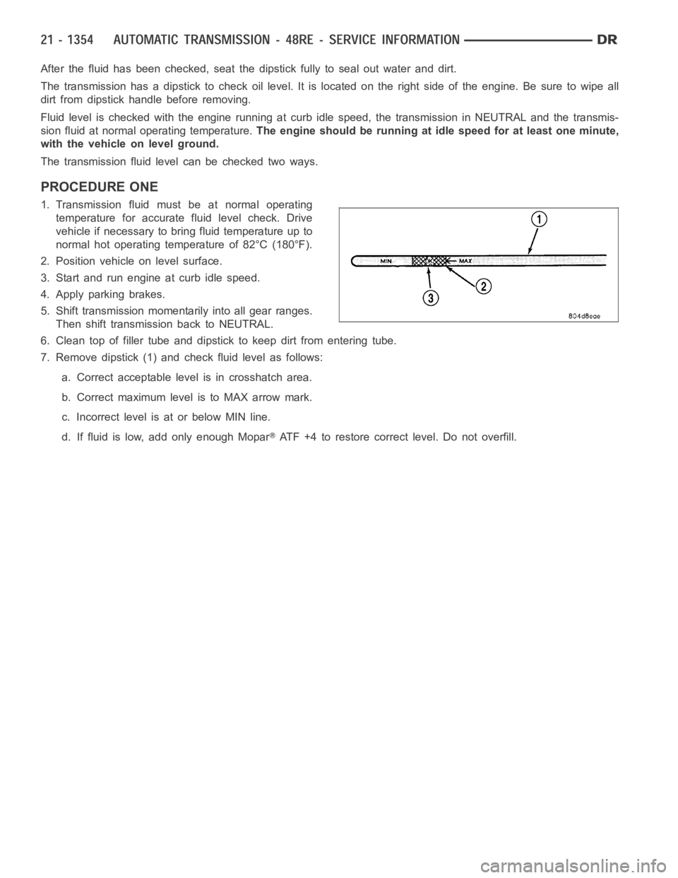
7. Remove dipstick (1) and check fluid level as follows:
a. Correct acceptable level is in crosshatch area.
b. Correct maximum level is to MAX arrow mark.
c. Incorrect level is at or below MIN line.
d. If fluid is low, add only enough Mopar
ATF +4 to restore correct level. Do not overfill.
Page 3876 of 5267

PROCEDURE TWO
1. Start engine and apply parking brake.
2. Shift the transmission into DRIVE for approximately 2 seconds.
3. Shift the transmission into REVERSE for approximately 2 seconds.
4. Shift the transmission into PARK.
5. Hook up DRB
scan tool and select engine.
6. Select sensors.
7. Read the transmission temperature value.
8. Compare the fluid temperature value with the chart.
9. Adjust transmission fluid level shown on the dipstick according to the chart.
NOTE: After adding any fluid to the transmission, wait a minimum of 2 minutes for the oil to fully drain from
the fill tube into the transmission before rechecking the fluid level.
10. Check transmission for leaks.
FLUID AND FILTER REPLACEMENT
For proper service intervals (Refer to LUBRICATION & MAINTENANCE/MAINTENANCE SCHEDULES - DESCRIP-
TION). The service fluid fill after a filter change is approximately 3.8 liters (4.0 quarts).
Page 3877 of 5267
REMOVAL
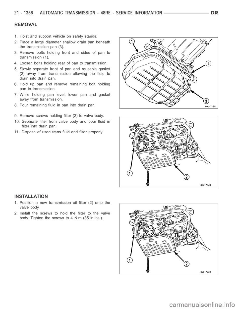
1. Hoist and support vehicle on safety stands.
2. Place a large diameter shallow drain pan beneath
the transmission pan (3).
3. Remove bolts holding front and sides of pan to
transmission (1).
4. Loosen bolts holding rear of pan to transmission.
5. Slowly separate front of pan and reusable gasket
(2) away from transmission allowing the fluid to
drain into drain pan.
6. Hold up pan and remove remaining bolt holding
pan to transmission.
7. While holding pan level, lower pan and gasket
away from transmission.
8. Pour remaining fluid in pan into drain pan.
9. Remove screws holding filter (2) to valve body.
10. Separate filter from valve body and pour fluid in
filter into drain pan.
11. Dispose of used trans fluid and filter properly.
INSTALLATION
1. Position a new transmission oil filter (2) onto the
valve body.
2. Install the screws to hold the filter to the valve
body. Tighten the screws to 4 Nꞏm (35 in.lbs.).
Page 3878 of 5267
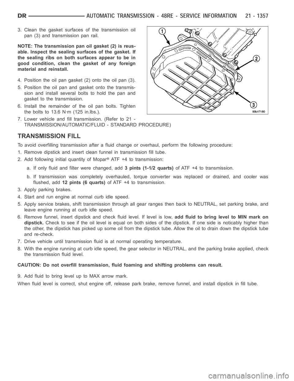
3. Clean the gasket surfaces of the transmission oil
pan (3) and transmission pan rail.
NOTE: The transmission pan oil gasket (2) is reus-
able. Inspect the sealing surfaces of the gasket. If
the sealing ribs on both surfaces appear to be in
good condition, clean the gasket of any foreign
material and reinstall.
4. Position the oil pan gasket (2) onto the oil pan (3).
5. Position the oil pan and gasket onto the transmis-
sion and install several bolts to hold the pan and
gasket to the transmission.
6. Install the remainder of the oil pan bolts. Tighten
the bolts to 13.6 Nꞏm (125 in.lbs.).
7. Lower vehicle and fill transmission. (Refer to 21 -
TRANSMISSION/AUTOMATIC/FLUID - STANDARD PROCEDURE)
TRANSMISSION FILL
To avoid overfilling transmission after a fluid change or overhaul, perform the following procedure:
1. Remove dipstick and insert clean funnel in transmission fill tube.
2. Add following initial quantity of Mopar
ATF+4totransmission:
a. If only fluid and filter were changed, add3 pints (1-1/2 quarts)of ATF +4 to transmission.
b. If transmission was completely overhauled, torque converter was replaced or drained, and cooler was
flushed, add12 pints (6 quarts)of ATF +4 to transmission.
3. Apply parking brakes.
4. Start and run engine at normal curb idle speed.
5. Apply service brakes, shift transmission through all gear ranges then back to NEUTRAL, set parking brake, and
leave engine running at curb idle speed.
6. Remove funnel, insert dipstick andcheck fluid level. If level is low,add fluid to bring level to MIN mark on
dipstick.Check to see if the oil level is equal on both sides of the dipstick. If one side is noticably higher than
the other, the dipstick has picked up some oil from the dipstick tube. Allowthe oil to drain down the dipstick tube
and re-check.
7. Drive vehicle until transmission fluid is at normal operating temperature.
8. With the engine running at curb idle speed, the gear selector in NEUTRAL,and the parking brake applied, check
the transmission fluid level.
CAUTION: Do not overfill transmission, fluid foaming and shifting problems can result.
9. Add fluid to bring level up to MAX arrow mark.
When fluid level is correct, shut engine off, release park brake, remove funnel, and install dipstick in fill tube.
Page 3899 of 5267
UNIT-OVERDRIVE
REMOVAL
1. Shift transmission into PARK.
2. Raise vehicle.
3. Remove transfer case, if equipped.
4. Mark propeller shaft universal joint(s) and axle pinion yoke, or the companion flange and flange yoke, for align-
ment reference at installation, if necessary.
5. Disconnect and remove the rear propeller shaft, if necessary. (Refer to3 - DIFFERENTIAL & DRIVELINE/PRO-
PELLER SHAFT/PROPELLER SHAFT - REMOVAL)
6. Remove transmission oil pan, remove gasket, drain oil and reinstall pan.
7. If overdrive unit had malfunctioned, or if fluid is contaminated, remove entire transmission. If diagnosis indicated
overdrive problems only, remove just the overdrive unit.
8. Support transmission with transmission jack.
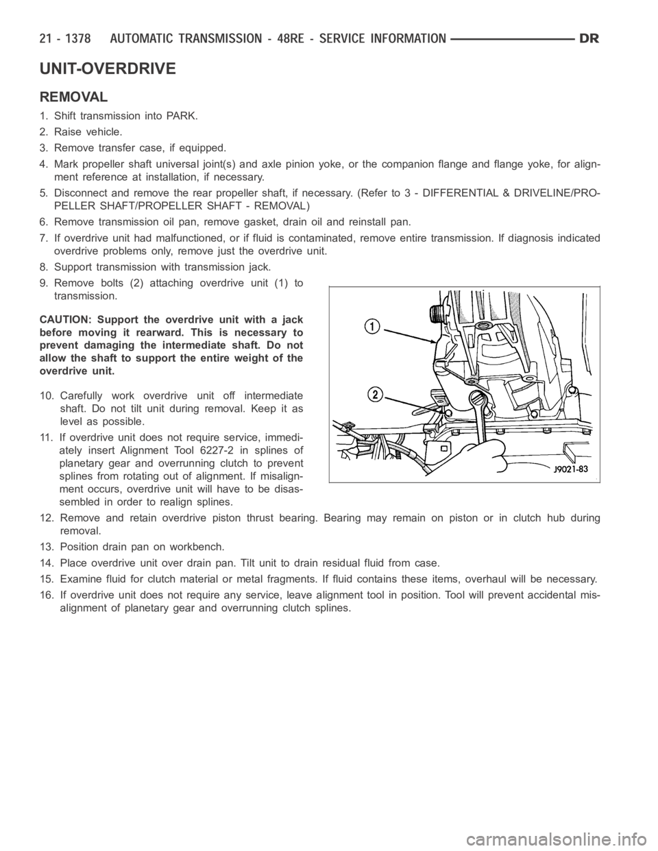
9. Remove bolts (2) attaching overdrive unit (1) to
transmission.
CAUTION: Support the overdrive unit with a jack
before moving it rearward. This is necessary to
prevent damaging the intermediate shaft. Do not
allow the shaft to support the entire weight of the
overdrive unit.
10. Carefully work overdrive unit off intermediate
shaft. Do not tilt unit during removal. Keep it as
level as possible.
11. If overdrive unit does not require service, immedi-
ately insert Alignment Tool 6227-2 in splines of
planetary gear and overrunning clutch to prevent
splines from rotating out of alignment. If misalign-
ment occurs, overdrive unit will have to be disas-
sembled in order to realign splines.
12. Remove and retain overdrive piston thrust bearing. Bearing may remainon piston or in clutch hub during
removal.
13. Position drain pan on workbench.
14. Place overdrive unit over drain pan. Tilt unit to drain residual fluid from case.
15. Examine fluid for clutch material or metal fragments. If fluid contains these items, overhaul will be necessary.
16. If overdrive unit does not require any service, leave alignment tool inposition. Tool will prevent accidental mis-
alignment of planetary gear and overrunning clutch splines.