2006 DODGE RAM SRT-10 oil level
[x] Cancel search: oil levelPage 3957 of 5267
STATOR
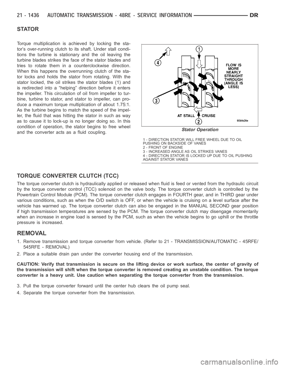
Torque multiplication is achieved by locking the sta-
tor’s over-running clutch to its shaft. Under stall condi-
tions the turbine is stationary and the oil leaving the
turbine blades strikes the face of the stator blades and
tries to rotate them in a counterclockwise direction.
When this happens the overrunning clutch of the sta-
tor locks and holds the stator from rotating. With the
stator locked, the oil strikes the stator blades (1) and
is redirected into a “helping” direction before it enters
the impeller. This circulation of oil from impeller to tur-
bine, turbine to stator, and stator to impeller, can pro-
duce a maximum torque multiplication of about 1.75:1.
As the turbine begins to match the speed of the impel-
ler, the fluid that was hitting the stator in such as way
as to cause it to lock-up is no longer doing so. In this
condition of operation, the stator begins to free wheel
and the converter acts as a fluid coupling.
TORQUE CONVERTER CLUTCH (TCC)
The torque converter clutch is hydraulically applied or released when fluid is feed or vented from the hydraulic circuit
by the torque converter control (TCC) solenoid on the valve body. The torque converter clutch is controlled by the
Powertrain Control Module (PCM). The torque converter clutch engages in FOURTH gear, and in THIRD gear under
various conditions, such as when the O/D switch is OFF, or when the vehicle is cruising on a level surface after the
vehicle has warmed up. The torque converter clutch can also be engaged in the MANUAL SECOND gear position
if high transmission temperatures are sensed by the PCM. The torque converter clutch may disengage momentarily
when an increase in engine load is sensed by the PCM, such as when the vehiclebegins to go uphill or the throttle
pressure is increased.
REMOVAL
1. Remove transmission and torque converter from vehicle. (Refer to 21 - TRANSMISSION/AUTOMATIC - 45RFE/
545RFE - REMOVAL)
2. Place a suitable drain pan under the converter housing end of the transmission.
CAUTION: Verify that transmission is secure on the lifting device or work surface, the center of gravity of
the transmission will shift when the torque converter is removed creatingan unstable condition. The torque
converter is a heavy unit. Use caution when separating the torque converter from the transmission.
3. Pull the torque converter forward until the center hub clears the oil pumpseal.
4. Separate the torque converter from the transmission.
Stator Operation
1 - DIRECTION STATOR WILL FREE WHEEL DUE TO OIL
PUSHING ON BACKSIDE OF VANES
2-FRONTOFENGINE
3 - INCREASED ANGLE AS OIL STRIKES VANES
4 - DIRECTION STATOR IS LOCKED UP DUE TO OIL PUSHING
AGAINST STATOR VANES
Page 4087 of 5267
Condition Possible Cause Correction
Lubricant leaking from output shaft
seal or vent.1) Transfer case overfilled. 1) Drain lubricant to the correct
level.
2) Vent closed or restricted. 2) Clear or replace vent as
necessary.
3) Output shaft seals damaged or
installed incorrectly.3) Replace seal as necessary.
Check to ensure that another
component, the propeller shaft slip
yoke for example, is not causing
damage to seal.
Abnormal tire wear. 1) Extended operation on hard, dry
surfaces in the 4H position.1) Operate vehicle in the 2H
position on hard, dry surfaces.
REMOVAL
1. Raise and support vehicle.
2. Remove skid plate, if equipped. (Refer to 13 - FRAMES & BUMPERS/FRAME/TRANSFER CASE SKID PLATE
- REMOVAL)
3. Position drain oil container under transfer case.
4. Remove transfer case drain plug and drain lubricant into container.
5. Disconnect vent hose and transfer case position sensor connector.
6. Disconnect shift rod from grommet in transfer case shift lever, or from floor shift arm whichever provides easy
access. Use channel lock style pliers to press rod out of lever grommet.
7. Support transmission with jack stand.
8. Mark front and rear propeller shafts for assembly reference.
9. Remove front and rear propeller shafts. (Refer to 3 - DIFFERENTIAL & DRIVELINE/PROPELLER SHAFT/PRO-
PELLER SHAFT - REMOVAL)
10. Support transfer case with suitable jack. Secure transfer case to jackwith safety chains.
11. Remove nuts attaching transfer case to transmission.
12. Move transfer case assembly rearward until free of transmission outputshaft.
13. Lower jack and move transfer case from under vehicle.
DISASSEMBLY
Position transfer case in a shallow drain pan. Remove drain plug and drain any remaining lubricant remaining in
case.
SHIFT LEVER AND FRONT OUTPUT SHAFT SEAL
1. Shift transfer case into NEUTRAL.
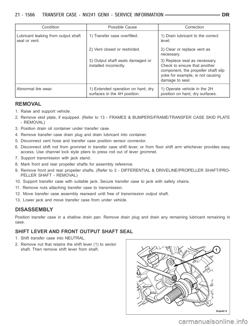
2. Remove nut that retains the shift lever (1) to sector
shaft. Then remove shift lever from shaft.
Page 4129 of 5267
Condition Possible Cause Correction
Lubricant leaking from output shaft
seal or vent.1) Transfer case overfilled. 1) Drain lubricant to the correct
level.
2) Vent closed or restricted. 2) Clear or replace vent as
necessary.
3) Output shaft seals damaged or
installed incorrectly.3) Replace seal as necessary.
Check to ensure that another
component, the propeller shaft slip
yoke for example, is not causing
damage to seal.
Abnormal tire wear. 1) Extended operation on hard, dry
surfaces in the 4H position.1) Operate vehicle in the 2H
position on hard, dry surfaces.
REMOVAL
1. Raise and support vehicle.
2. Remove skid plate, if equipped. (Refer to 13 - FRAMES & BUMPERS/FRAME/TRANSFER CASE SKID PLATE
- REMOVAL)
3. Position drain oil container under transfer case.
4. Remove transfer case drain plug and drain lubricant into container.
5. Disconnect vent hose and transfer case position sensor connector.
6. Disconnect shift rod from grommet in transfer case shift lever, or from floor shift arm whichever provides easy
access. Use channel lock style pliers to press rod out of lever grommet.
7. Support transmission with jack stand.
8. Mark front and rear propeller shafts for assembly reference.
9. Remove front and rear propeller shafts. (Refer to 3 - DIFFERENTIAL & DRIVELINE/PROPELLER SHAFT/PRO-
PELLER SHAFT - REMOVAL)
10. Support transfer case with suitable jack. Secure transfer case to jackwith safety chains.
11. Remove nuts attaching transfer case to transmission.
12. Move transfer case assembly rearward until free of transmission outputshaft.
13. Lower jack and move transfer case from under vehicle.
DISASSEMBLY
Position transfer case in a shallow drain pan. Remove drain plug and drain any remaining lubricant remaining in
case.
Page 5053 of 5267
ACTUATOR DTC DETECTION TEST — DUAL-ZONE
The Actuator DTC Detection Test:
is actuated with a scan tool.
clears all actuator related DTCs when the test is actuated.
supplements the continuous diagnostics on the actuator drive system.
monitors for shorted actuator circuits allowing service to easily diagnose and troubleshoot up to three simul-
taneous shorts. Shorted actuator circuit faults (XXX Control Circuit High or XXX Control Circuit Low) will only
display after running the Actuator DTC Detection Test.
After repairing each DTC, cycle the ignition switch, and then run the Actuator DTC Detection Test again to ensure
that no new DTCs exist. If multiple DTCs are present, beginning with the passenger blend door, diagnose and repair
all short high faults and then short low faults. When the test returns passed, clear all faults and run the Actuator
Calibration function as a final check of system health.
ACTUATOR DTC DETECTION TEST — SINGLE-ZONE
The Actuator DTC Detection Test:
is actuated with a scan tool.
clears all actuator related DTCs when the test is actuated.
supplements the continuous diagnostics on the actuator drive system.
monitors for shorted actuator circuits allowing service to easily diagnose and troubleshoot up to three simul-
taneous shorts. Shorted actuator circuit faults (XXX Control Circuit High or XXX Control Circuit Low) will only
display after running the Actuator DTC Detection Test.
After repairing each DTC, cycle the ignition switch, and then run the Actuator DTC Detection Test again to ensure
that no new DTCs exist. If multiple DTCs are present, beginning with the common circuit, diagnose and repair all
short high faults and then short low faults. When the test returns passed, clear all faults and run the Actuator Cal-
ibration function as a final check of system health.
A/C PERFORMANCE
The A/C system is designed to provide the passenger compartment with low temperature and low humidity air. The
A/C evaporator, located in the HVAC housing is cooled to temperatures nearthe freezing point. As warm damp air
passes over the fins of the A/C evaporator, the air transfers its heat to therefrigerant in the evaporator coils and the
moisture in the air condenses on the evaporator fins. During periods of high heat and humidity, an A/C system will
be more effective in the Recirculation mode (max-A/C). With the system in the Recirculation mode, only air from the
passenger compartment passes through the A/C evaporator. As the passenger compartment air dehumidifies, the
A/C system performance levels rise.
Humidity has an important bearing on the temperature of the air delivered to the interior of the vehicle. It is impor-
tant to understand the effect that humidity has on the performance of the A/C system. When humidity is high, the
A/C evaporator has to perform a double duty. It must lower the air temperature, and it must lower the temperature
of the moisture in the air that condenses on the evaporator fins. Condensing the moisture in the air transfers heat
energy into the evaporator fins and coils. This reduces the amount of heat the A/C evaporator can absorb from the
air. High humidity greatly reduces the ability of the A/C evaporator to lower the temperature of the air.
However, evaporator capacity used to reduce the amount of moisture in the air is not wasted. Wringing some of the
moisture out of the air entering the vehicle adds to the comfort of the passengers. Although, an owner may expect
too much from their A/C system on humid days. A performance test is the best way to determine whether the sys-
tem is performing up to design standards. This test also provides valuableclues as to the possible cause of trouble
with the A/C system. The ambient air temperature in the location where the vehicle will be tested must be a mini-
mum of 21° C (70° F) for this test.
A/C PERFORMANCE TEST
WARNING: Refer to the applicable warnings and cautions for this system before performing the following
operation (Refer to 24 - HEATING & AIR CONDITIONING/PLUMBING - WARNINGS) and (Refer to 24 - HEAT-
ING & AIR CONDITIONING/PLUMBING - CAUTIONS). Failure to follow the warnings and cautions could result
in possible personal injury or death.
Page 5055 of 5267
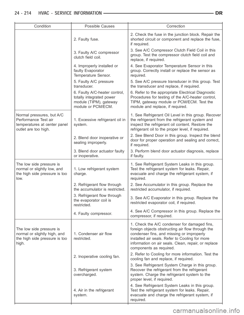
Condition Possible Causes Correction
2. Faulty fuse.2. Check the fuse in the junction block. Repair the
shorted circuit or component and replace the fuse,
if required.
3. Faulty A/C compressor
clutch field coil.3. See A/C Compressor Clutch Field Coil in this
group. Test the compressor clutch field coil and
replace, if required.
4. Improperly installed or
faulty Evaporator
Temperature Sensor.4. See Evaporator Temperature Sensor in this
group. Correctly install or replace the sensor as
required.
5. Faulty A/C pressure
transducer.5. See A/C pressure transducer in this group. Test
the transducer and replace, if required.
6. Faulty A/C-heater control,
totally integrated power
module (TIPM), gateway
module or PCM/ECM.6. Refer to the appropriate Electrical Diagnostic
Procedures for testing of the A/C-heater control,
TIPM, gateway module or PCM/ECM. Test the
module and replace, if required.
Normal pressures, but A/C
Performance Test air
temperatures at center panel
outlet are too high.1. Excessive refrigerant oil in
system.1. See Refrigerant Oil Level in this group. Recover
the refrigerant from the refrigerant system and
inspect the refrigerant oil content. Restore the
refrigerant oil to the proper level, if required.
2. Blend door inoperative or
sealing improperly.2. See Blend Door in this group. Inspect the blend
door for proper operation and sealing and correct,
if required.
3. Blend door actuator faulty
or inoperative.3. Perform blend door actuator diagnosis, replace
if faulty.
The low side pressure is
normal or slightly low, and
the high side pressure is too
low.1. Low refrigerant system
charge.1. See Refrigerant System Leaks in this group.
Test the refrigerant system for leaks. Repair,
evacuate and charge the refrigerant system, if
required.
2. Refrigerant flow through
the accumulator is restricted.2. See Accumulator in this group. Replace the
restricted accumulator, if required.
3. Refrigerant flow through
the evaporator coil is
restricted.3. See A/C Evaporator in this group. Replace the
restricted evaporator coil, if required.
4. Faulty compressor.4. See A/C Compressor in this group. Replace the
compressor, if required.
The low side pressure is
normal or slightly high, and
the high side pressure is too
high.1. Condenser air flow
restricted.1. Check the A/C condenser for damaged fins,
foreign objects obstructing air flow through the
condenser fins, and missing or improperly
installed air seals. Refer to Cooling for more
information on air seals. Clean, repair, or replace
components as required.
2. Inoperative cooling fan.2. Refer to Cooling for more information. Test the
cooling fan and replace, if required.
3. Refrigerant system
overcharged.3. See Refrigerant System Charge in this group.
Recover the refrigerant from the refrigerant
system. Charge the refrigerant system to the
proper level, if required.
4. Air in the refrigerant
system.4. See Refrigerant System Leaks in this group.
Test the refrigerant system for leaks. Repair,
evacuate and charge the refrigerant system, if
required.
Page 5073 of 5267
CLUTCH-A/C COMPRESSOR
DESCRIPTION
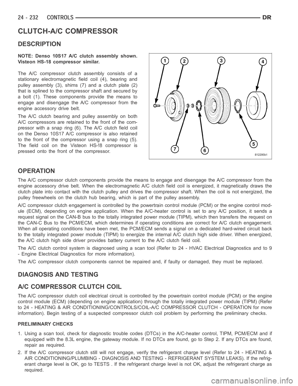
NOTE: Denso 10S17 A/C clutch assembly shown.
Visteon HS-18 compressor similar.
The A/C compressor clutch assembly consists of a
stationary electromagnetic field coil (4), bearing and
pulley assembly (3), shims (7) and a clutch plate (2)
that is splined to the compressor shaft and secured by
a bolt (1). These components provide the means to
engage and disengage the A/C compressor from the
engine accessory drive belt.
The A/C clutch bearing and pulley assembly on both
A/C compressors are retained to the front of the com-
pressor with a snap ring (6). The A/C clutch field coil
on the Denso 10S17 A/C compressor is also retained
to the front of the compressor using a snap ring (5).
The field coil on the Visteon HS-!8 compressor is
pressed onto the front of the compressor.
OPERATION
The A/C compressor clutch components provide the means to engage and disengage the A/C compressor from the
engine accessory drive belt. When the electromagnetic A/C clutch field coil is energized, it magnetically draws the
clutch plate into contact with the clutch pulley and drives the compressorshaft. When the coil is not energized, the
pulley freewheels on the clutch hub bearing, which is part of the pulley assembly.
A/C compressor clutch engagement is controlled by the powertrain controlmodule (PCM) or the engine control mod-
ule (ECM), depending on engine application. When the A/C-heater control is set to any A/C position, it sends a
request signal on the CAN-B bus to the totally integrated power module (TIPM), which then transfers the request on
the CAN-C Bus to the PCM/ECM, which determines if operating conditions arecorrect for A/C clutch engagement.
When all operating conditions have been met, the PCM/ECM sends a signal on adedicated hard-wired circuit back
to the totally integrated power module (TIPM) to energize the internal A/Cclutch high side driver. When energized,
the A/C clutch high side driver provides battery current to the A/C clutch field coil.
The A/C clutch control system is diagnosed using a scan tool (Refer to 24 - HVAC Electrical Diagnostics and to 9
- Engine Electrical Diagnostics for more information).
The A/C compressor clutch components cannot be repaired and, if faulty or damaged, they must be replaced.
DIAGNOSIS AND TESTING
A/CCOMPRESSORCLUTCHCOIL
The A/C compressor clutch coil electrical circuit is controlled by the powertrain control module (PCM) or the engine
control module (ECM) (depending on engine application) through the totally integrated power module (TIPM) (Refer
to 24 - HEATING & AIR CONDITIONING/CONTROLS/COIL-A/C COMPRESSOR CLUTCH -OPERATION for more
information). Begin testing of a suspected compressor clutch coil problem by performing the preliminary checks.
PRELIMINARY CHECKS
1. Using a scan tool, check for diagnostic trouble codes (DTCs) in the A/C-heater control, TIPM, PCM/ECM and if
equipped with the 8.3L engine, the gateway module. If no DTCs are found, go to Step 2. If any DTCs are found,
repair as required.
2. If the A/C compressor clutch still will not engage, verify the refrigerant charge level (Refer to 24 - HEATING &
AIR CONDITIONING/PLUMBING - DIAGNOSIS AND TESTING - REFRIGERANT SYSTEM LEAKS). If the refrig-
erant charge level is OK, go to TESTS . If the refrigerant charge level is notOK, adjust the refrigerant charge as
required.
Page 5126 of 5267

5.9L DIESEL ENGINE ...................... 343
8.3L ENGINE .............................. 345
OIL-A/C REFRIGERANT
DESCRIPTION ............................... 347
OPERATION ................................. 347
STANDARD PROCEDURE
REFRIGERANT OIL LEVEL ................. 347
REFRIGERANT-A/C
DESCRIPTION ............................... 349OPERATION ................................. 349
TUBE-A/C ORIFICE
DESCRIPTION ............................... 350
OPERATION ................................. 350
DIAGNOSIS AND TESTING
A/C ORIFICE TUBE ........................ 350
Page 5129 of 5267
DIAGNOSIS AND TESTING
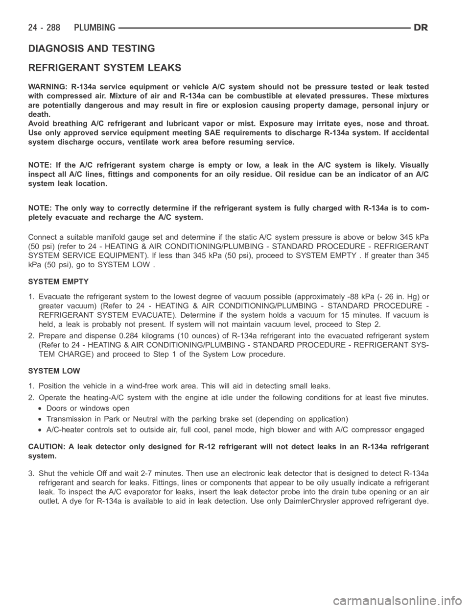
REFRIGERANT SYSTEM LEAKS
WARNING: R-134a service equipment or vehicle A/C system should not be pressure tested or leak tested
with compressed air. Mixture of air and R-134a can be combustible at elevated pressures. These mixtures
are potentially dangerous and may result in fire or explosion causing property damage, personal injury or
death.
Avoid breathing A/C refrigerant and lubricant vapor or mist. Exposure mayirritate eyes, nose and throat.
Use only approved service equipment meeting SAE requirements to discharge R-134a system. If accidental
system discharge occurs, ventilate work area before resuming service.
NOTE: If the A/C refrigerant system charge is empty or low, a leak in the A/C system is likely. Visually
inspect all A/C lines, fittings and components for an oily residue. Oil residue can be an indicator of an A/C
system leak location.
NOTE: The only way to correctly determine if the refrigerant system is fully charged with R-134a is to com-
pletely evacuate and recharge the A/C system.
Connect a suitable manifold gauge setand determine if the static A/C system pressure is above or below 345 kPa
(50 psi) (refer to 24 - HEATING & AIR CONDITIONING/PLUMBING - STANDARD PROCEDURE - REFRIGERANT
SYSTEM SERVICE EQUIPMENT). If less than 345 kPa (50 psi), proceed to SYSTEMEMPTY . If greater than 345
kPa (50 psi), go to SYSTEM LOW .
SYSTEM EMPTY
1. Evacuate the refrigerant system to the lowest degree of vacuum possible(approximately -88 kPa (- 26 in. Hg) or
greater vacuum) (Refer to 24 - HEATING & AIR CONDITIONING/PLUMBING - STANDARD PROCEDURE -
REFRIGERANT SYSTEM EVACUATE). Determine if the system holds a vacuum for 15 minutes. If vacuum is
held, a leak is probably not present. If system will not maintain vacuum level, proceed to Step 2.
2. Prepare and dispense 0.284 kilograms (10 ounces) of R-134a refrigerantinto the evacuated refrigerant system
(Refer to 24 - HEATING & AIR CONDITIONING/PLUMBING - STANDARD PROCEDURE - REFRIGERANT SYS-
TEM CHARGE) and proceed to Step 1 of the System Low procedure.
SYSTEM LOW
1. Position the vehicle in a wind-freework area. This will aid in detectingsmall leaks.
2. Operate the heating-A/C system with the engine at idle under the following conditions for at least five minutes.
Doors or windows open
Transmission in Park or Neutral with the parking brake set (depending on application)
A/C-heater controls set to outside air, full cool, panel mode, high blowerand with A/C compressor engaged
CAUTION: A leak detector only designed for R-12 refrigerant will not detect leaks in an R-134a refrigerant
system.
3. Shut the vehicle Off and wait 2-7 minutes. Then use an electronic leak detector that is designed to detect R-134a
refrigerant and search for leaks. Fittings, lines or components that appear to be oily usually indicate a refrigerant
leak. To inspect the A/C evaporator for leaks, insert the leak detector probe into the drain tube opening or an air
outlet. A dye for R-134a is available to aid in leak detection. Use only DaimlerChrysler approved refrigerant dye.