2006 DODGE RAM SRT-10 ignition
[x] Cancel search: ignitionPage 3428 of 5267
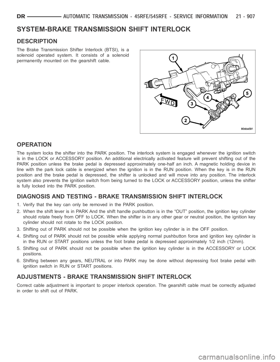
SYSTEM-BRAKE TRANSMISSION SHIFT INTERLOCK
DESCRIPTION
The Brake Transmission Shifter Interlock (BTSI), is a
solenoid operated system. It consists of a solenoid
permanently mounted on the gearshift cable.
OPERATION
The system locks the shifter into the PARK position. The interlock system is engaged whenever the ignition switch
is in the LOCK or ACCESSORY position. An additional electrically activated feature will prevent shifting out of the
PARK position unless the brake pedal is depressed approximately one-halfan inch. A magnetic holding device in
line with the park lock cable is energized when the ignition is in the RUN position. When the key is in the RUN
position and the brake pedal is depressed, the shifter is unlocked and willmove into any position. The interlock
system also prevents the ignition switch from being turned to the LOCK or ACCESSORY position, unless the shifter
is fully locked into the PARK position.
DIAGNOSIS AND TESTING - BRAKE TRANSMISSION SHIFT INTERLOCK
1. Verify that the key can only be removed in the PARK position.
2. When the shift lever is in PARK And the shift handle pushbutton is in the “OUT” position, the ignition key cylinder
should rotate freely from OFF to LOCK. When the shifter is in any other gear or neutral position, the ignition key
cylinder should not rotate to the LOCK position.
3. Shifting out of PARK should not be possible when the ignition key cylinder is in the OFF position.
4. Shifting out of PARK should not be possible while applying normal pushbutton force and ignition key cylinder is
in the RUN or START positions unless the foot brake pedal is depressed approximately 1/2 inch (12mm).
5. Shifting out of PARK should not be possible when the ignition key cylinderisintheACCESSORYorLOCK
positions.
6. Shifting between any gears, NEUTRAL or into PARK may be done without depressing foot brake pedal with
ignition switch in RUN or START positions.
ADJUSTMENTS - BRAKE TRANSMISSION SHIFT INTERLOCK
Correct cable adjustment is important to proper interlock operation. Thegearshift cable must be correctly adjusted
in order to shift out of PARK.
Page 3429 of 5267
ADJUSTMENT PROCEDURE
1. Remove the steering column trim as necessary for
access to the brake transmission shift interlock.
2. Shift the transmission into the PARK position.
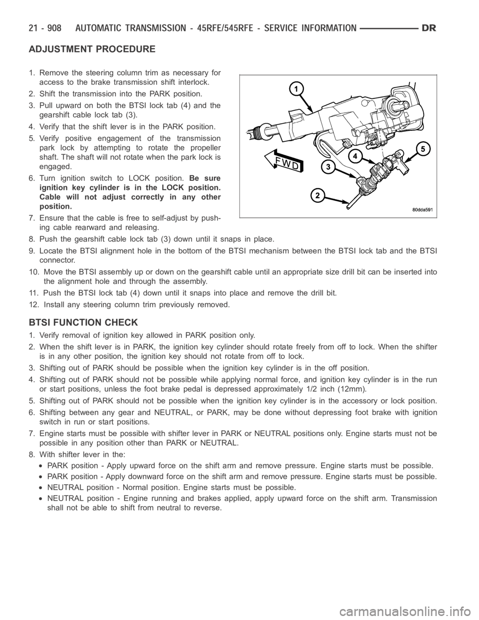
3. Pull upward on both the BTSI lock tab (4) and the
gearshift cable lock tab (3).
4. Verify that the shift lever is in the PARK position.
5. Verify positive engagement of the transmission
park lock by attempting to rotate the propeller
shaft. The shaft will not rotate when the park lock is
engaged.
6. Turn ignition switch to LOCK position.Be sure
ignition key cylinder is in the LOCK position.
Cable will not adjust correctly in any other
position.
7. Ensure that the cable is free to self-adjust by push-
ing cable rearward and releasing.
8. Push the gearshift cable lock tab (3) down until it snaps in place.
9. Locate the BTSI alignment hole in the bottom of the BTSI mechanism betweentheBTSIlocktabandtheBTSI
connector.
10. Move the BTSI assembly up or down on the gearshift cable until an appropriate size drill bit can be inserted into
the alignment hole and through the assembly.
11. Push the BTSI lock tab (4) down until it snaps into place and remove the drill bit.
12. Install any steering column trim previously removed.
BTSI FUNCTION CHECK
1. Verify removal of ignition key allowed in PARK position only.
2. When the shift lever is in PARK, the ignition key cylinder should rotate freely from off to lock. When the shifter
is in any other position, the ignition key should not rotate from off to lock.
3. Shifting out of PARK should be possible when the ignition key cylinder isin the off position.
4. Shifting out of PARK should not be possible while applying normal force,and ignition key cylinder is in the run
or start positions, unless the foot brake pedal is depressed approximately1/2inch(12mm).
5. Shifting out of PARK should not be possible when the ignition key cylinder is in the accessory or lock position.
6. Shifting between any gear and NEUTRAL, or PARK, may be done without depressing foot brake with ignition
switch in run or start positions.
7. Engine starts must be possible with shifter lever in PARK or NEUTRAL positions only. Engine starts must not be
possible in any position other than PARK or NEUTRAL.
8. With shifter lever in the:
PARK position - Apply upward force on the shift arm and remove pressure. Enginestartsmustbepossible.
PARK position - Apply downward force on the shift arm and remove pressure. Engine starts must be possible.
NEUTRAL position - Normal position. Engine starts must be possible.
NEUTRAL position - Engine running and brakes applied, apply upward force on the shift arm. Transmission
shall not be able to shift from neutral to reverse.
Page 3474 of 5267
SWITCH-TOW/HAUL OVERDRIVE
DESCRIPTION
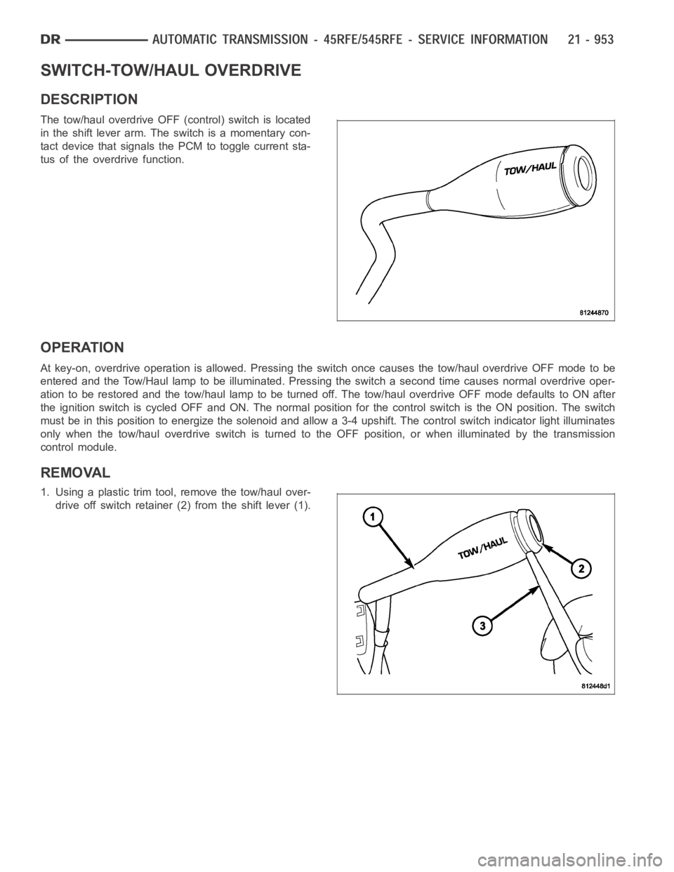
The tow/haul overdrive OFF (control) switch is located
in the shift lever arm. The switch is a momentary con-
tact device that signals the PCM to toggle current sta-
tus of the overdrive function.
OPERATION
At key-on, overdrive operation is allowed. Pressing the switch once causes the tow/haul overdrive OFF mode to be
entered and the Tow/Haul lamp to be illuminated. Pressing the switch a second time causes normal overdrive oper-
ationtoberestoredandthetow/haullamptobeturnedoff.Thetow/hauloverdrive OFF mode defaults to ON after
the ignition switch is cycled OFF and ON. The normal position for the control switch is the ON position. The switch
must be in this position to energize the solenoid and allow a 3-4 upshift. The control switch indicator light illuminates
only when the tow/haul overdrive switch is turned to the OFF position, or when illuminated by the transmission
control module.
REMOVAL
1. Using a plastic trim tool, remove the tow/haul over-
drive off switch retainer (2) from the shift lever (1).
Page 3511 of 5267
Theory of Operation
The Transmission Temperature Sensor is used to sense when the transmissiontemperatureistoohotortoocoldto
operate overdrive and/or the torque convertor clutch. When the transmission sensor detects a temperature below 0°
C (32° F), overdrive and the torque convertor clutch are disabled. When thedetected temperature is above 127° C
(260° F), overdrive is disabled and 3rd gear with TCC is engaged, this strategy is used to increase transmission
fluid flow to help cool the transmission.
When Monitored:
Continuously with the ignition on and the engine running.
Set Condition:
The DTC will set after two consecutive trips in which the transmission oil temperature is greater than 5° C (40°
F) and the transmission oil temperature does not rise more than 8° C (16° F) after 20 minutes of run time with
a vehicle speed greater than 48 Kmh (30 mph). The DTC will also set if the engine temperature is greater than
38° C (100° F) with the transmission oil temperature greater than 127° C (260° F).
Possible Causes
OTHER TRANSMISSION DTC’S SET
INTERMITTENT TRANSMISSION TEMPERATURE SENSOR
TRANSMISSION TEMPERATURE SENSOR
Always perform the Pre-Diagnostic Troubleshooting procedure before proceeding. (Refer to 21 - TRANSMIS-
SION/TRANSAXLE/AUTOMATIC - 48RE - STANDARD PROCEDURE)
Diagnostic Test
1.CHECK IF THE DTC IS CURRENT
Ignition on, engine not running.
With the scan tool, read Engine DTCs.
Record the Freeze Frame data for the reported DTC.
With the scan tool, erase DTCs.
Turn the ignition off to the lock position.
Using the Freeze Frame data recorded earlier, try to duplicate the conditions in which the DTC originally set.
NOTE: It may be necessary to road test the vehicle to duplicate the originalset conditions.
With the scan tool, read Engine DTCs.
Did the DTC reset?
Ye s>>
Go To 2
No>>
Go To 6
2.CHECK FOR OTHER TRANSMISSION DTCS
Does the scan tool show any Park/Neutral DTCs?
Ye s>>
Refer to the Transmission category and perform the appropriate symptom(s).
No>>
Go To 3
Page 3513 of 5267
Turn the ignition off to the lock position.
Remove the Transmission Oil Pan per the Service Information. (Refer to 21 -TRANSMISSION/TRANSAXLE/AU-
TOMATIC - 48RE/FLUID - STANDARD PROCEDURE)
Disconnect the Governor Pressure Sensor harness connector internal to the transmission.
NOTE: Check connectors - Clean/repair as necessary
Measure the resistance of the Transmission Temperature Sensor between the (T54) Transmission Temperature Sen-
sor Signal circuit and the (K900) Sensor Ground circuit.
Using the chart at the chart above, compare the Temperature Sensor temperature to the correlating resistance
value.
Is the resistance within the specified range when the sensor is at the giventemperature?
Ye s>>
Te s t C o m p l e t e .
No>>
Replace the Governor Pressure/Transmission Temperature Sensor per the Service Information. (Refer to
21 - TRANSMISSION/TRANSAXLE/AUTOMATIC - 48RE/GOVERNOR PRESSURE SENSOR-
REMOVAL)
Perform RE TRANSMISSION VERIFICATION TEST VER - 1 (GAS). (Refer to 21 - TRANSMISSION/
TRANSAXLE/AUTOMATIC - 48RE - STANDARD PROCEDURE)
6.INTERMITTENT WIRING AND CONNECTORS
The conditions necessary to set this DTC are not present at this time.
Use the Freeze Frame Data to help duplicate the conditions in which the DTC originally set. Pay particular attention
to the DTC set conditions, such as, VSS, MAP, ECT, and Load.
Using the schematics as a guide, visually inspect the related wiring harness. Look for any chafed, pierced, pinched,
or partially broken wires.
Visually inspect the related wiring harness connectors. Look for broken,bent, pushed out, or corroded terminals.
Wiggle the wiring and connectors while checking for any possible open or shorted circuits.
Check for any Service Information Tune-ups or Technical Service Bulletins that may apply.
Were there any problems found?
Ye s>>
Repair as necessary.
Perform RE TRANSMISSION VERIFICATION TEST VER - 1 (GAS). (Refer to 21 - TRANSMISSION/
TRANSAXLE/AUTOMATIC - 48RE - STANDARD PROCEDURE)
No>>
Te s t C o m p l e t e .
Page 3515 of 5267
Theory of Operation
The Transmission Temperature Sensor is used to sense when the transmissiontemperatureistoohotortoocoldto
operate overdrive and/or the torque convertor clutch. When the transmission sensor detects a temperature below 0°
C (32° F), overdrive and the torque convertor clutch are disabled. When thedetected temperature is above 127° C
(260° F), overdrive is disabled and 3rd gear with TCC is engaged, this strategy is used to increase transmission
fluid flow to help cool the transmission.
When Monitored:
Continuously with the ignition on and the engine running.
Set Condition:
The DTC will set if the monitored Transmission Temperature Sensor Signal circuit drops below 1.55 volts for
the period of 2.25 seconds.
Possible Causes
(T54) TRANSMISSION TEMPERATURE SENSOR SIGNAL CIRCUIT SHORT TO GROUND
(T54) TRANSMISSION TEMPERATURE SENSOR SIGNAL CIRCUIT SHORT TO (K900) SENSOR GROUND
CIRCUIT
(T54) TRANSMISSION TEMPERATURE SENSOR SIGNAL CIRCUIT SHORT TO GROUND INSIDE
TRANSMISSION
(T54) TRANSMISSION TEMPERATURE SENSOR SIGNAL CIRCUIT SHORT TO THE (K900)SENSOR GROUND
CIRCUIT INSIDE TRANSMISSION
TRANSMISSION TEMPERATURE SENSOR
POWERTRAIN CONTROL MODULE
Always perform the Pre-Diagnostic Troubleshooting procedure before proceeding. (Refer to 21 - TRANSMIS-
SION/TRANSAXLE/AUTOMATIC - 48RE - STANDARD PROCEDURE)
Diagnostic Test
1.CHECK IF THE DTC IS CURRENT
Ignition on, engine not running.
With the scan tool, read Engine DTCs.
Record the Freeze Frame data for the reported DTC.
With the scan tool, erase DTCs.
Turn the ignition off to the lock position.
Using the Freeze Frame data recorded earlier, try to duplicate the conditions in which the DTC originally set.
NOTE: It may be necessary to road test the vehicle to duplicate the originalset conditions.
With the scan tool, read Engine DTCs.
Did the DTC reset?
Ye s>>
Go To 2
No>>
Go To 8
Page 3516 of 5267
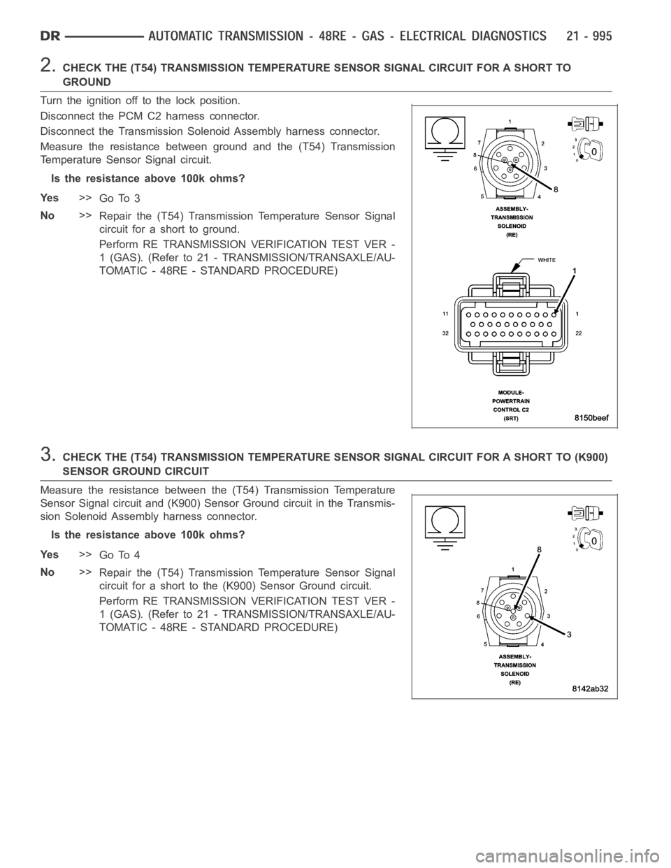
2.CHECK THE (T54) TRANSMISSION TEMPERATURE SENSOR SIGNAL CIRCUIT FOR A SHORTTO
GROUND
Turn the ignition off to the lock position.
Disconnect the PCM C2 harness connector.
Disconnect the Transmission Solenoid Assembly harness connector.
Measure the resistance between ground and the (T54) Transmission
Temperature Sensor Signal circuit.
Is the resistance above 100k ohms?
Ye s>>
Go To 3
No>>
Repair the (T54) Transmission Temperature Sensor Signal
circuit for a short to ground.
Perform RE TRANSMISSION VERIFICATION TEST VER -
1 (GAS). (Refer to 21 - TRANSMISSION/TRANSAXLE/AU-
TOMATIC - 48RE - STANDARD PROCEDURE)
3.CHECK THE (T54) TRANSMISSION TEMPERATURE SENSOR SIGNAL CIRCUIT FOR A SHORT TO (K900)
SENSOR GROUND CIRCUIT
Measure the resistance between the (T54) Transmission Temperature
Sensor Signal circuit and (K900) Sensor Ground circuit in the Transmis-
sion Solenoid Assembly harness connector.
Is the resistance above 100k ohms?
Ye s>>
Go To 4
No>>
Repair the (T54) Transmission Temperature Sensor Signal
circuit for a short to the (K900) Sensor Ground circuit.
Perform RE TRANSMISSION VERIFICATION TEST VER -
1 (GAS). (Refer to 21 - TRANSMISSION/TRANSAXLE/AU-
TOMATIC - 48RE - STANDARD PROCEDURE)
Page 3518 of 5267
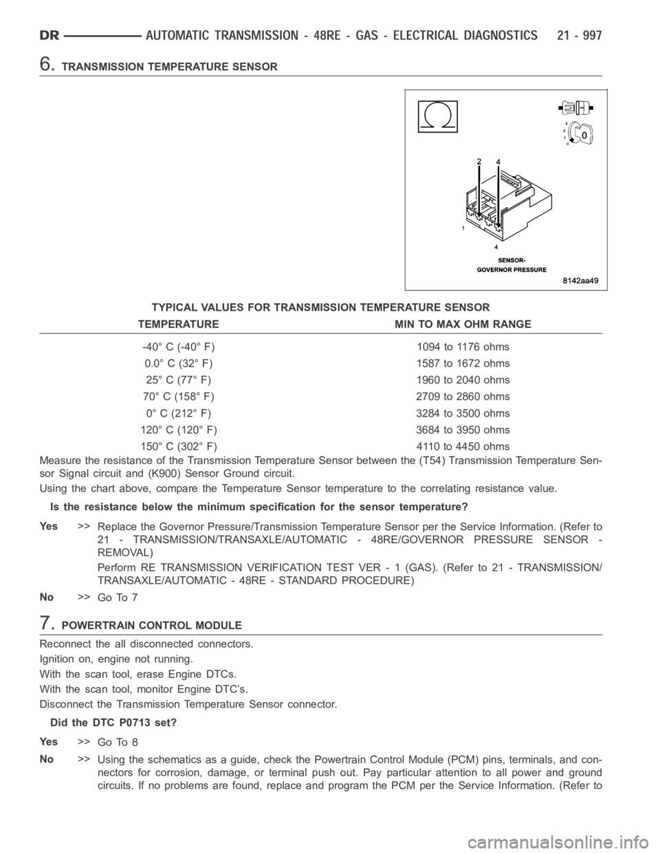
6.TRANSMISSION TEMPERATURE SENSOR
TYPICAL VALUES FOR TRANSMISSION TEMPERATURE SENSOR
TEMPERATURE MIN TO MAX OHM RANGE
-40° C (-40° F) 1094 to 1176 ohms
0.0° C (32° F) 1587 to 1672 ohms
25° C (77° F) 1960 to 2040 ohms
70° C (158° F) 2709 to 2860 ohms
0° C (212° F) 3284 to 3500 ohms
120° C (120° F) 3684 to 3950 ohms
150° C (302° F) 4110 to 4450 ohms
Measure the resistance of the Transmission Temperature Sensor between the (T54) Transmission Temperature Sen-
sor Signal circuit and (K900) Sensor Ground circuit.
Using the chart above, compare the Temperature Sensor temperature to the correlating resistance value.
Is the resistance below the minimum specification for the sensor temperature?
Ye s>>
Replace the Governor Pressure/Transmission Temperature Sensor per the Service Information. (Refer to
21 - TRANSMISSION/TRANSAXLE/AUTOMATIC - 48RE/GOVERNOR PRESSURE SENSOR-
REMOVAL)
Perform RE TRANSMISSION VERIFICATION TEST VER - 1 (GAS). (Refer to 21 - TRANSMISSION/
TRANSAXLE/AUTOMATIC - 48RE - STANDARD PROCEDURE)
No>>
Go To 7
7.POWERTRAIN CONTROL MODULE
Reconnect the all disconnected connectors.
Ignition on, engine not running.
With the scan tool, erase Engine DTCs.
With the scan tool, monitor Engine DTC’s.
Disconnect the Transmission Temperature Sensor connector.
Did the DTC P0713 set?
Ye s>>
Go To 8
No>>
Using the schematics as a guide, check the Powertrain Control Module (PCM)pins, terminals, and con-
nectors for corrosion, damage, or terminal push out. Pay particular attention to all power and ground
circuits. If no problems are found, replace and program the PCM per the Service Information. (Refer to