Page 1639 of 5267
19. Install A/C compressor (2) (Refer to 24 - HEAT-
ING & AIR CONDITIONING/PLUMBING/A/C
COMPRESSOR - INSTALLATION).
20. Install both breathers (1). Connect tube to both
crankcase breathers.
21. Connect throttle and speed control cables.
22. Install throttle body resonator assembly and air
inlet hose. Tighten clamps 4 Nꞏm (35 in. lbs.).
23. Raise vehicle.
24. Install transmission to engine mounting bolts.
Tighten the bolts to 41 Nꞏm (30 ft. lbs.).
25. Install torque converter bolts (Automatic Transmis-
sion Only).
26. Connect crankshaft position sensor (1).
27.4X4 vehiclesPosition and install the axle isolator
bracket onto the axle, transmission and engine
block. Tighten bolts to specification (Refer to 9 -
ENGINE - SPECIFICATIONS).
Page 1642 of 5267

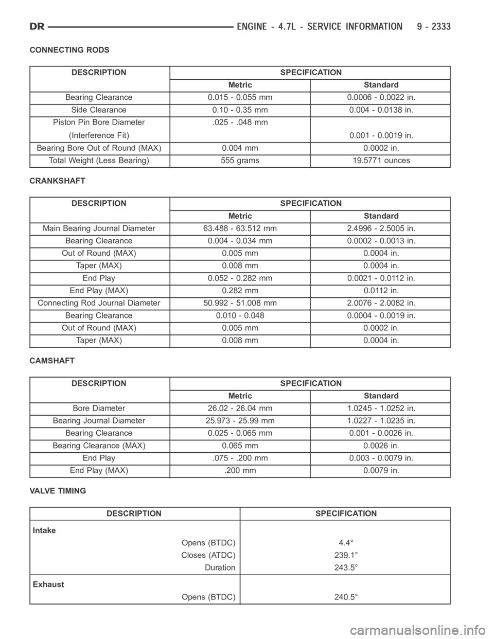
CONNECTING RODS
DESCRIPTION SPECIFICATION
Metric Standard
Bearing Clearance 0.015 - 0.055 mm 0.0006 - 0.0022 in.
Side Clearance 0.10 - 0.35 mm 0.004 - 0.0138 in.
Piston Pin Bore Diameter .025 - .048 mm
(Interference Fit) 0.001 - 0.0019 in.
Bearing Bore Out of Round (MAX) 0.004 mm 0.0002 in.
Total Weight (Less Bearing) 555 grams 19.5771 ounces
CRANKSHAFT
DESCRIPTION SPECIFICATION
Metric Standard
Main Bearing Journal Diameter 63.488 - 63.512 mm 2.4996 - 2.5005 in.
Bearing Clearance 0.004 - 0.034 mm 0.0002 - 0.0013 in.
Out of Round (MAX) 0.005 mm 0.0004 in.
Taper (MAX) 0.008 mm 0.0004 in.
End Play 0.052 - 0.282 mm 0.0021 - 0.0112 in.
End Play (MAX) 0.282 mm 0.0112 in.
Connecting Rod Journal Diameter 50.992 - 51.008 mm 2.0076 - 2.0082 in.
Bearing Clearance 0.010 - 0.048 0.0004 - 0.0019 in.
Out of Round (MAX) 0.005 mm 0.0002 in.
Taper (MAX) 0.008 mm 0.0004 in.
CAMSHAFT
DESCRIPTION SPECIFICATION
Metric Standard
Bore Diameter 26.02 - 26.04 mm 1.0245 - 1.0252 in.
Bearing Journal Diameter 25.973 - 25.99 mm 1.0227 - 1.0235 in.
Bearing Clearance 0.025 - 0.065 mm 0.001 - 0.0026 in.
BearingClearance(MAX) 0.065mm 0.0026in.
End Play .075 - .200 mm 0.003 - 0.0079 in.
End Play (MAX) .200 mm 0.0079 in.
VALVE TIMING
DESCRIPTION SPECIFICATION
Intake
Opens (BTDC) 4.4°
Closes (ATDC) 239.1°
Duration 243.5°
Exhaust
Opens (BTDC) 240.5°
Page 1645 of 5267

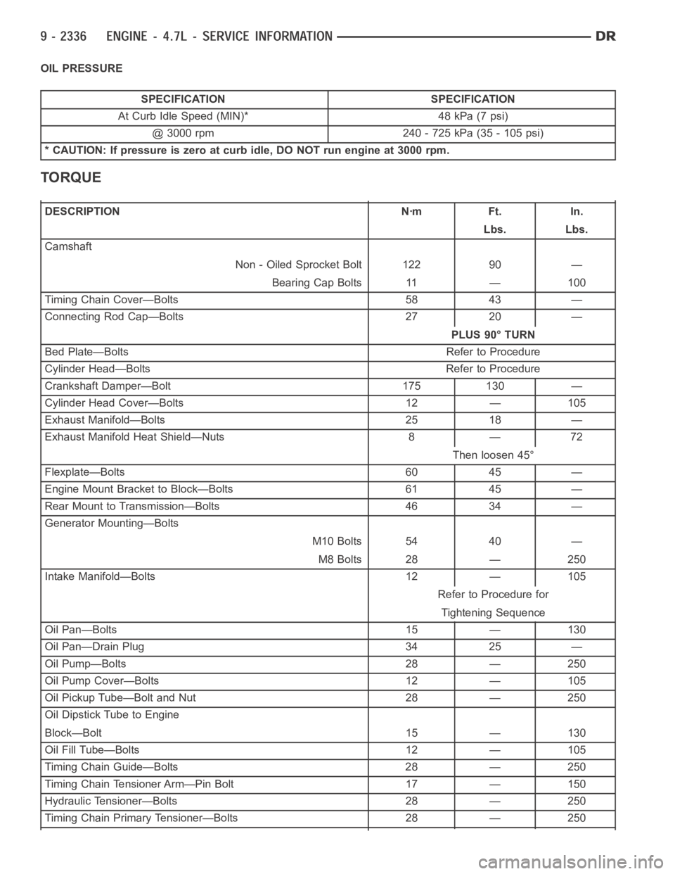
OIL PRESSURE
SPECIFICATION SPECIFICATION
At Curb Idle Speed (MIN)* 48 kPa (7 psi)
@ 3000 rpm 240 - 725 kPa (35 - 105 psi)
* CAUTION: If pressure is zero at curb idle, DO NOT run engine at 3000 rpm.
TORQUE
DESCRIPTION Nꞏm Ft. In.
Lbs. Lbs.
Camshaft
Non - Oiled Sprocket Bolt 122 90 —
Bearing Cap Bolts 11 — 100
Timing Chain Cover—Bolts 58 43 —
Connecting Rod Cap—Bolts 27 20 —
PLUS 90° TURN
Bed Plate—Bolts Refer to Procedure
Cylinder Head—Bolts Refer to Procedure
Crankshaft Damper—Bolt 175 130 —
Cylinder Head Cover—Bolts 12 — 105
Exhaust Manifold—Bolts 25 18 —
Exhaust Manifold Heat Shield—Nuts 8 — 72
Then loosen 45°
Flexplate—Bolts 60 45 —
Engine Mount Bracket to Block—Bolts 61 45 —
Rear Mount to Transmission—Bolts 46 34 —
Generator Mounting—Bolts
M10 Bolts 54 40 —
M8 Bolts 28 — 250
Intake Manifold—Bolts 12 — 105
Refer to Procedure for
Tightening Sequence
Oil Pan—Bolts 15 — 130
Oil Pan—Drain Plug 34 25 —
Oil Pump—Bolts 28 — 250
Oil Pump Cover—Bolts 12 — 105
Oil Pickup Tube—Bolt and Nut 28 — 250
Oil Dipstick Tube to Engine
Block—Bolt 15 — 130
Oil Fill Tube—Bolts 12 — 105
Timing Chain Guide—Bolts 28 — 250
Timing Chain Tensioner Arm—Pin Bolt 17 — 150
Hydraulic Tensioner—Bolts 28 — 250
Timing Chain Primary Tensioner—Bolts 28 — 250
Page 1647 of 5267
SPECIAL TOOLS
4.7L ENGINE
Spanner Wrench 6958
Adapter Pins 8346
Engine Lifting Studs 8400
Engine Lift Fixture 8347
Front Crankshaft Seal Remover 8511
Front Crankshaft Seal Installer 8348
Handle C-4171
Rear Crankshaft Seal Installer 8349
Page 1648 of 5267
Rear Crankshaft Seal Remover 8506
Connecting Rod Guides 8507
Crankshaft Damper Installer 8512
Puller 1026
Crankshaft Damper Removal Insert 8513
Chain Tensioner Wedge 8379
Chain Tensioner Pins 8514
Secondary Chain Holder 8515
Remover, Rocker Arm 8516
Page 1654 of 5267

Install Cooling System Tester Special Tool # 7700 or equivalent to pressure cap neck. Start the engine and observe
the tester’s pressure gauge. If gauge pulsates with every power stroke of acylinder a combustion pressure leak is
evident.
CHEMICAL TEST METHOD
Combustion leaks into the cooling system can also be checked by using Bloc-Chek Kit Special Tool # C-3685-A or
equivalent. Perform test following the procedures supplied with the toolkit.
REMOVAL
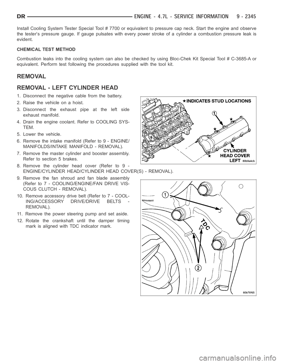
REMOVAL - LEFT CYLINDER HEAD
1. Disconnect the negative cable from the battery.
2. Raise the vehicle on a hoist.
3. Disconnect the exhaust pipe at the left side
exhaust manifold.
4. Drain the engine coolant. Refer to COOLING SYS-
TEM.
5. Lower the vehicle.
6. Remove the intake manifold (Refer to 9 - ENGINE/
MANIFOLDS/INTAKE MANIFOLD - REMOVAL).
7. Remove the master cylinder and booster assembly.
Refer to section 5 brakes.
8. Remove the cylinder head cover (Refer to 9 -
ENGINE/CYLINDER HEAD/CYLINDER HEAD COVER(S) - REMOVAL).
9. Remove the fan shroud and fan blade assembly
(Refer to 7 - COOLING/ENGINE/FAN DRIVE VIS-
COUS CLUTCH - REMOVAL).
10. Remove accessory drive belt (Refer to 7 - COOL-
ING/ACCESSORY DRIVE/DRIVE BELTS -
REMOVAL).
11. Remove the power steering pump and set aside.
12. Rotate the crankshaft until the damper timing
mark is aligned with TDC indicator mark.
Page 1655 of 5267
13. Verify the V8 mark on the camshaft sprocket is at the 12 o’clock position. Rotate the crankshaft one turn if
necessary.
14. Remove the crankshaft damper (Refer to 9 - ENGINE/ENGINE BLOCK/VIBRATION DAMPER - REMOVAL).
15. Remove the timing chain cover (Refer to 9 - ENGINE/VALVE TIMING/TIMINGBELT / CHAIN COVER(S) -
REMOVAL).
16. Lock the secondary timing chains to the idler
sprocket using Special Tool 8515.
Page 1657 of 5267

CAUTION: Do not lay the cylinder head on its gasket sealing surface, due to the design of the cylinder head
gasket any distortion to the cylinder head sealing surface may prevent thegasket from properly sealing
resulting in leaks.
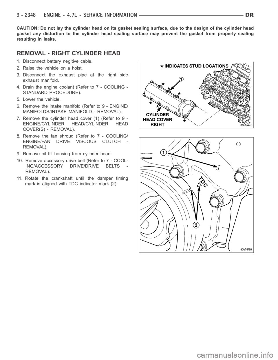
REMOVAL - RIGHT CYLINDER HEAD
1. Disconnect battery negitive cable.
2. Raise the vehicle on a hoist.
3. Disconnect the exhaust pipe at the right side
exhaust manifold.
4. Drain the engine coolant (Refer to 7 - COOLING -
STANDARD PROCEDURE).
5. Lower the vehicle.
6. Remove the intake manifold (Refer to 9 - ENGINE/
MANIFOLDS/INTAKE MANIFOLD - REMOVAL).
7. Remove the cylinder head cover (1) (Refer to 9 -
ENGINE/CYLINDER HEAD/CYLINDER HEAD
COVER(S) - REMOVAL).
8. Remove the fan shroud (Refer to 7 - COOLING/
ENGINE/FAN DRIVE VISCOUS CLUTCH -
REMOVAL).
9. Remove oil fill housing from cylinder head.
10. Remove accessory drive belt (Refer to 7 - COOL-
ING/ACCESSORY DRIVE/DRIVE BELTS -
REMOVAL).
11. Rotate the crankshaft until the damper timing
mark is aligned with TDC indicator mark (2).