Page 1596 of 5267
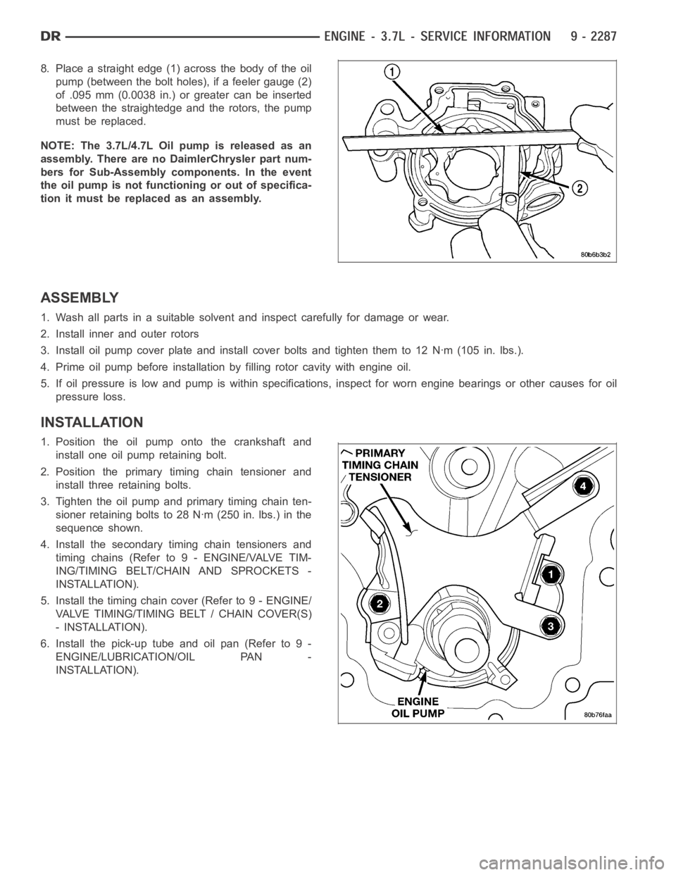
8. Place a straight edge (1) across the body of the oil
pump (between the bolt holes), if a feeler gauge (2)
of .095 mm (0.0038 in.) or greater can be inserted
between the straightedge and the rotors, the pump
must be replaced.
NOTE: The 3.7L/4.7L Oil pump is released as an
assembly. There are no DaimlerChrysler part num-
bers for Sub-Assembly components. In the event
the oil pump is not functioning or out of specifica-
tion it must be replaced as an assembly.
ASSEMBLY
1. Wash all parts in a suitable solvent and inspect carefully for damage or wear.
2. Install inner and outer rotors
3. Install oil pump cover plate and install cover bolts and tighten them to 12Nꞏm(105in.lbs.).
4. Prime oil pump before installation by filling rotor cavity with engine oil.
5. If oil pressure is low and pump is within specifications, inspect for worn engine bearings or other causes for oil
pressure loss.
INSTALLATION
1. Position the oil pump onto the crankshaft and
install one oil pump retaining bolt.
2. Position the primary timing chain tensioner and
install three retaining bolts.
3. Tighten the oil pump and primary timing chain ten-
sioner retaining bolts to 28 Nꞏm (250 in. lbs.) in the
sequence shown.
4. Install the secondary timing chain tensioners and
timing chains (Refer to 9 - ENGINE/VALVE TIM-
ING/TIMING BELT/CHAIN AND SPROCKETS -
INSTALLATION).
5. Install the timing chain cover (Refer to 9 - ENGINE/
VALVE TIMING/TIMING BELT / CHAIN COVER(S)
- INSTALLATION).
6. Install the pick-up tube and oil pan (Refer to 9 -
ENGINE/LUBRICATION/OIL PAN -
INSTALLATION).
Page 1606 of 5267
VALVE TIMING
DESCRIPTION
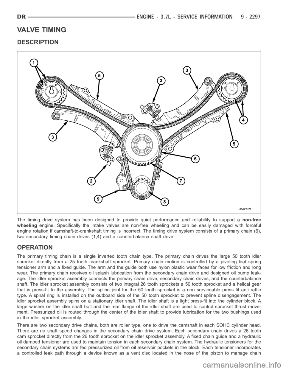
The timing drive system has been designed to provide quiet performance andreliability to support anon-free
wheelingengine. Specifically the intake valves are non-free wheeling and can be easily damaged with forceful
engine rotation if camshaft-to-crankshaft timing is incorrect. The timing drive system consists of a primary chain (6),
two secondary timing chain drives (1,4) and a counterbalance shaft drive.
OPERATION
The primary timing chain is a single inverted tooth chain type. The primarychaindrivesthelarge50toothidler
sprocket directly from a 25 tooth crankshaft sprocket. Primary chain motion is controlled by a pivoting leaf spring
tensioner arm and a fixed guide. The arm and the guide both use nylon plasticwear faces for low friction and long
wear. The primary chain receives oil splash lubrication from the secondary chain drive and designed oil pump leak-
age. The idler sprocket assembly connects the primary chain drive, secondary chain drives, and the counterbalance
shaft. The idler sprocket assembly consists of two integral 26 tooth sprockets a 50 tooth sprocket and a helical gear
that is press-fit to the assembly. Thespline joint for the 50 tooth sprocket is a non serviceable press fit anti rattle
type. A spiral ring is installed on the outboard side of the 50 tooth sprocket to prevent spline disengagement. The
idler sprocket assembly spins on a stationary idler shaft. The idler shaftis a light press-fit into the cylinder block. A
large washer on the idler shaft bolt and the rear flange of the idler shaft are used to control sprocket thrust move-
ment. Pressurized oil is routed through the center of the idler shaft to provide lubrication for the two bushings used
in the idler sprocket assembly.
There are two secondary drive chains, both are roller type, one to drive thecamshaft in each SOHC cylinder head.
There are no shaft speed changes in the secondary chain drive system. Each secondary chain drives a 26 tooth
cam sprocket directly from the 26 tooth sprocket on the idler sprocket assembly. A fixed chain guide and a hydraulic
oil damped tensioner are used to maintain tension in each secondary chain system. The hydraulic tensioners for the
secondary chain systems are fed pressurized oil from oil reservoir pockets in the block. Each tensioner incorporates
a controlled leak path through a device known as a vent disc located in the nose of the piston to manage chain
Page 1608 of 5267
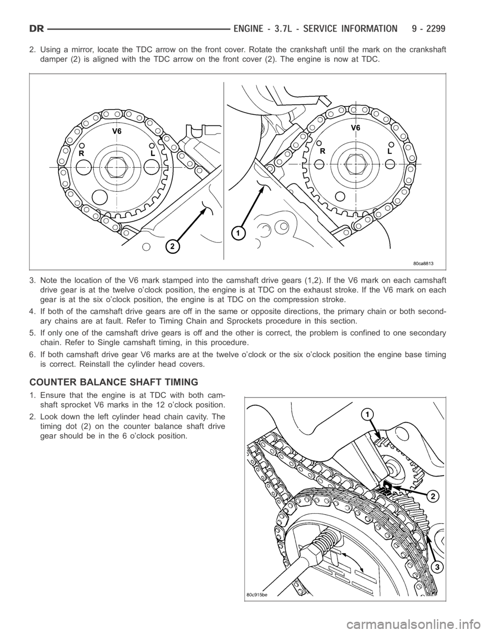
2. Using a mirror, locate the TDC arrow on the front cover. Rotate the crankshaft until the mark on the crankshaft
damper (2) is aligned with the TDC arrow on the front cover (2). The engine isnow at TDC.
3. Note the location of the V6 mark stamped into the camshaft drive gears (1,2). If the V6 mark on each camshaft
drive gear is at the twelve o’clock position, the engine is at TDC on the exhaust stroke. If the V6 mark on each
gear is at the six o’clock position, the engine is at TDC on the compression stroke.
4. If both of the camshaft drive gears are off in the same or opposite directions, the primary chain or both second-
ary chains are at fault. Refer to Timing Chain and Sprockets procedure in this section.
5. If only one of the camshaft drive gears is off and the other is correct, theproblem is confined to one secondary
chain. Refer to Single camshaft timing, in this procedure.
6. If both camshaft drive gear V6 marks are at the twelve o’clock or the six o’clock position the engine base timing
is correct. Reinstall the cylinder head covers.
COUNTER BALANCE SHAFT TIMING
1. Ensure that the engine is at TDC with both cam-
shaft sprocket V6 marks in the 12 o’clock position.
2. Look down the left cylinder head chain cavity. The
timing dot (2) on the counter balance shaft drive
gear should be in the 6 o’clock position.
Page 1610 of 5267
4. Re-index the camshaft drive gear in the chain until the V6 mark is at the same position as the V6 mark on the
opposite camshaft drive gear (1,2).
5. Using Special Tool 8428 Camshaft Wrench, rotate the camshaft until the alignment dowel on the camshaft is
aligned with the slot in the camshaft drive gear.
CAUTION: Remove excess oil from camshaft sprocket retaining bolt before reinstalling bolt. Failure to do so
may cause over-torqueing of bolt resulting in bolt failure.
6. Position the camshaft drive gear onto the camshaft, remove oil from boltthen install the retaining bolt. Using
Special Tools, Spanner Wrench 6958 with Adapter Pins 8346 and a suitable torque wrench, Tighten retaining bolt
to 122 Nꞏm (90 ft. Lbs.).
7. Remove Special Tool 8379.
8. Rotate the crankshaft two full revolutions, then verify that the camshaftdrivegearV6marksareinfactaligned.
9. Install the cylinder head covers. Refer to Cylinder Head Cover in this section.
Page 1614 of 5267
COVER-TIMING
REMOVAL
1. Disconnect the battery negative cable.
2. Drain cooling system (Refer to 7 - COOLING -
STANDARD PROCEDURE).
3. Remove electric cooling fan and fan shroud assem-
bly.
4. Remove fan and fan drive assembly (Refer to 7 -
COOLING/ENGINE/FAN DRIVE VISCOUS
CLUTCH - REMOVAL).
5. Disconnect both heater hoses at timing cover.
6. Disconnect lower radiator hose at engine.
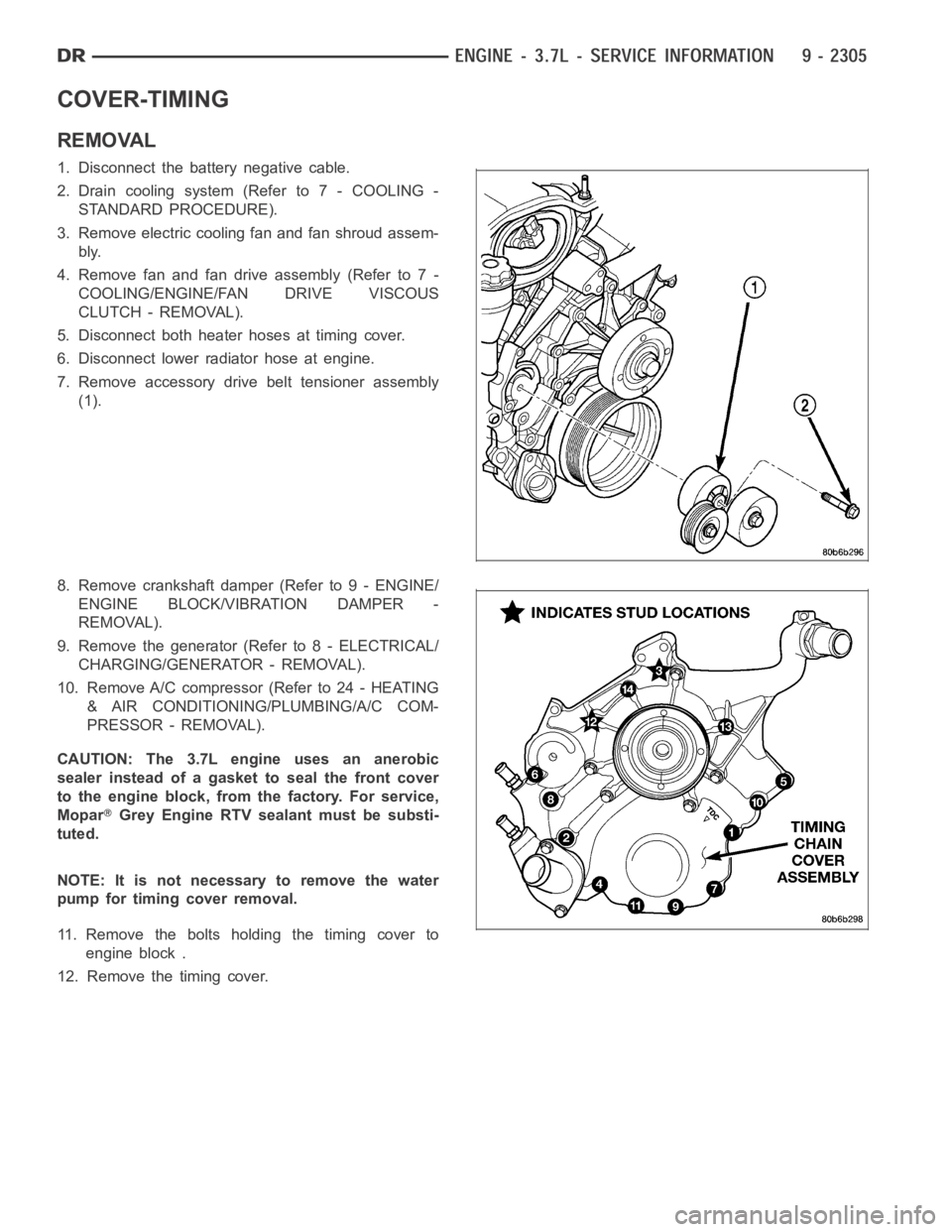
7. Remove accessory drive belt tensioner assembly
(1).
8. Remove crankshaft damper (Refer to 9 - ENGINE/
ENGINE BLOCK/VIBRATION DAMPER -
REMOVAL).
9. Remove the generator (Refer to 8 - ELECTRICAL/
CHARGING/GENERATOR - REMOVAL).
10. Remove A/C compressor (Refer to 24 - HEATING
& AIR CONDITIONING/PLUMBING/A/C COM-
PRESSOR - REMOVAL).
CAUTION: The 3.7L engine uses an anerobic
sealer instead of a gasket to seal the front cover
to the engine block, from the factory. For service,
Mopar
Grey Engine RTV sealant must be substi-
tuted.
NOTE: It is not necessary to remove the water
pump for timing cover removal.
11. Remove the bolts holding the timing cover to
engine block .
12. Remove the timing cover.
Page 1615 of 5267
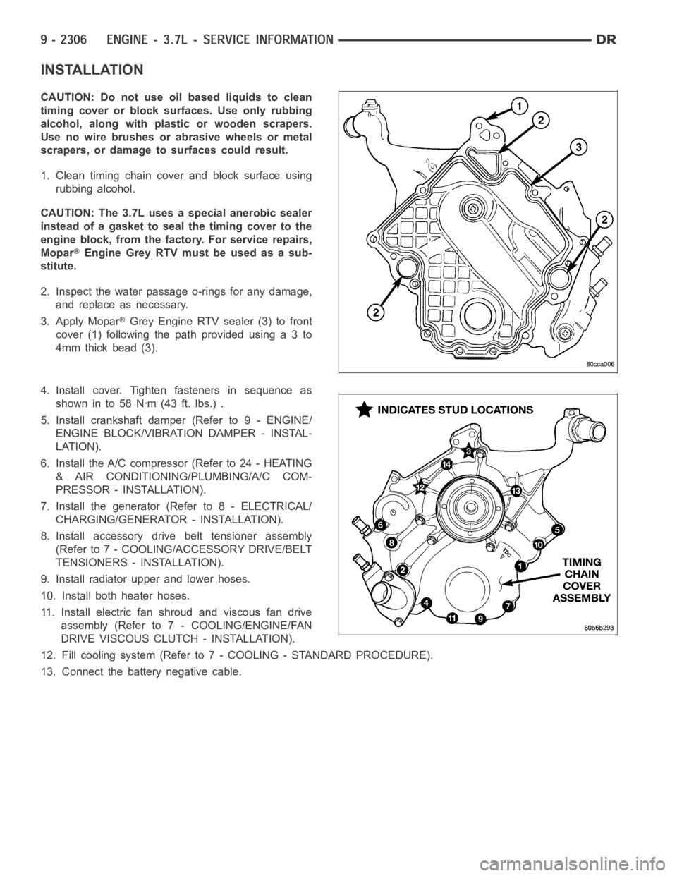
INSTALLATION
CAUTION: Do not use oil based liquids to clean
timing cover or block surfaces. Use only rubbing
alcohol, along with plastic or wooden scrapers.
Use no wire brushes or abrasive wheels or metal
scrapers, or damage to surfaces could result.
1. Clean timing chain cover and block surface using
rubbing alcohol.
CAUTION: The 3.7L uses a special anerobic sealer
instead of a gasket to seal the timing cover to the
engine block, from the factory. For service repairs,
Mopar
Engine Grey RTV must be used as a sub-
stitute.
2. Inspect the water passage o-rings for any damage,
and replace as necessary.
3. Apply Mopar
Grey Engine RTV sealer (3) to front
cover(1)followingthepathprovidedusinga3to
4mm thick bead (3).
4. Install cover. Tighten fasteners in sequence as
showninto58Nꞏm(43ft.lbs.).
5. Install crankshaft damper (Refer to 9 - ENGINE/
ENGINE BLOCK/VIBRATION DAMPER - INSTAL-
LATION).
6. Install the A/C compressor (Refer to 24 - HEATING
& AIR CONDITIONING/PLUMBING/A/C COM-
PRESSOR - INSTALLATION).
7. Install the generator (Refer to 8 - ELECTRICAL/
CHARGING/GENERATOR - INSTALLATION).
8. Install accessory drive belt tensioner assembly
(Refer to 7 - COOLING/ACCESSORY DRIVE/BELT
TENSIONERS - INSTALLATION).
9. Install radiator upper and lower hoses.
10. Install both heater hoses.
11. Install electric fan shroud and viscous fan drive
assembly (Refer to 7 - COOLING/ENGINE/FAN
DRIVE VISCOUS CLUTCH - INSTALLATION).
12. Fill cooling system (Refer to 7 - COOLING - STANDARD PROCEDURE).
13. Connect the battery negative cable.
Page 1616 of 5267
CHAIN AND SPROCKETS-TIMING
REMOVAL
1. Disconnect negative cable from battery.
2. Drain cooling system (Refer to 7 - COOLING -
STANDARD PROCEDURE).
3. Remove right and left cylinder head covers (Refer
to 9 - ENGINE/CYLINDER HEAD/CYLINDER
HEAD COVER(S) - REMOVAL).
4. Remove radiator fan shroud (Refer to 7 - COOL-
ING/ENGINE/RADIATOR FAN - REMOVAL).
5. Rotate engine until timing mark on crankshaft
damper (2) aligns with TDC mark on timing chain
cover (2) and the camshaft sprocket “V6” marks
are at the 12 o’clock position (No. 1 TDC exhaust
stroke).
Page 1617 of 5267
6. Remove power steering pump (Refer to 19 -
STEERING/PUMP - REMOVAL).
7. Remove access plug from left and right cylinder
heads for access to chain guide fasteners.
8. Remove the oil fill housing to gain access to the
right side tensioner arm fastener.
9. Remove crankshaft damper (Refer to 9 - ENGINE/
ENGINE BLOCK/VIBRATION DAMPER -
REMOVAL) and timing chain cover (Refer to 9 -
ENGINE/VALVE TIMING/TIMING BELT / CHAIN
COVER(S) - REMOVAL).
10. Collapse and pin primary chain tensioner.
CAUTION: Plate behind left secondary chain ten-
sioner could fall into oil pan. Therefore, cover pan
opening.
11. Remove secondary chain tensioners.
12. Remove camshaft position sensor (2).