2006 DODGE RAM SRT-10 sensor
[x] Cancel search: sensorPage 3614 of 5267
10.ENGINE CONTROL MODULE
Turn the ignition off to the lock position.
Reconnect the PCM harness connector.
Reconnect the Transmission Solenoid Assembly harness connector.
Ignition on, engine not running.
With the scan tool, erase DTCs.
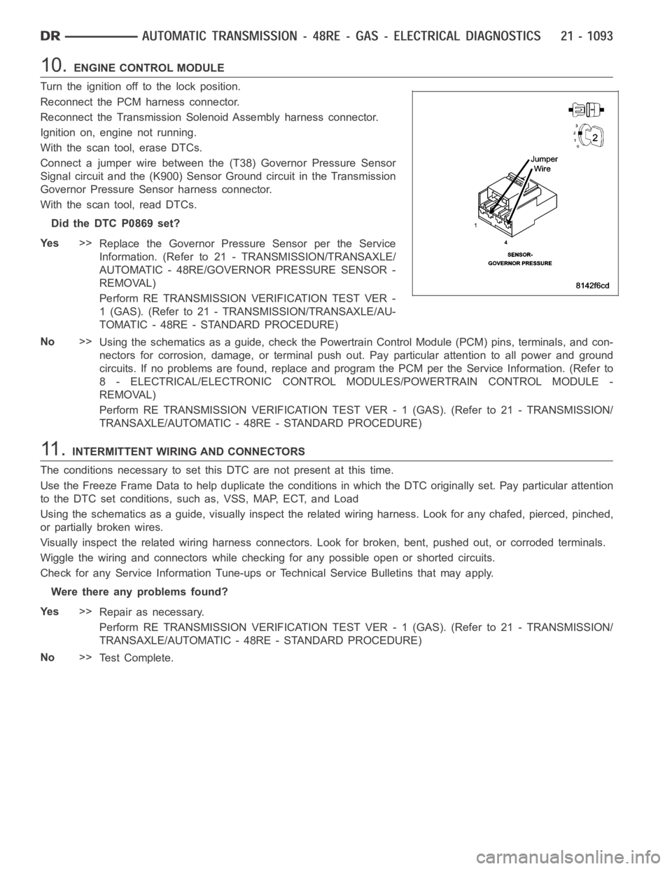
Connect a jumper wire between the (T38) Governor Pressure Sensor
Signal circuit and the (K900) Sensor Ground circuit in the Transmission
Governor Pressure Sensor harness connector.
With the scan tool, read DTCs.
Did the DTC P0869 set?
Ye s>>
Replace the Governor Pressure Sensor per the Service
Information. (Refer to 21 - TRANSMISSION/TRANSAXLE/
AUTOMATIC - 48RE/GOVERNOR PRESSURE SENSOR -
REMOVAL)
Perform RE TRANSMISSION VERIFICATION TEST VER -
1 (GAS). (Refer to 21 - TRANSMISSION/TRANSAXLE/AU-
TOMATIC - 48RE - STANDARD PROCEDURE)
No>>
Using the schematics as a guide, check the Powertrain Control Module (PCM)pins, terminals, and con-
nectors for corrosion, damage, or terminal push out. Pay particular attention to all power and ground
circuits. If no problems are found, replace and program the PCM per the Service Information. (Refer to
8 - ELECTRICAL/ELECTRONIC CONTROL MODULES/POWERTRAIN CONTROL MODULE -
REMOVAL)
Perform RE TRANSMISSION VERIFICATION TEST VER - 1 (GAS). (Refer to 21 - TRANSMISSION/
TRANSAXLE/AUTOMATIC - 48RE - STANDARD PROCEDURE)
11 .INTERMITTENT WIRING AND CONNECTORS
The conditions necessary to set this DTC are not present at this time.
Use the Freeze Frame Data to help duplicate the conditions in which the DTC originally set. Pay particular attention
to the DTC set conditions, such as, VSS, MAP, ECT, and Load
Using the schematics as a guide, visually inspect the related wiring harness. Look for any chafed, pierced, pinched,
or partially broken wires.
Visually inspect the related wiring harness connectors. Look for broken,bent, pushed out, or corroded terminals.
Wiggle the wiring and connectors while checking for any possible open or shorted circuits.
Check for any Service Information Tune-ups or Technical Service Bulletins that may apply.
Were there any problems found?
Ye s>>
Repair as necessary.
Perform RE TRANSMISSION VERIFICATION TEST VER - 1 (GAS). (Refer to 21 - TRANSMISSION/
TRANSAXLE/AUTOMATIC - 48RE - STANDARD PROCEDURE)
No>>
Te s t C o m p l e t e .
Page 3615 of 5267

P1764-GOVERNOR PRESSURE SENSOR VOLTS TOO LOW (GAS)
For a complete wiring diagramRefer to Section 8W
Page 3616 of 5267
Theory of Operation
The Governor Pressure Sensor is used by the PCM to adjust the Governor Pressure to a desired level for shifts in
first, second, and third gear. If the PCM detects the monitored sense voltage is greater than or less than a prede-
termined specification, the PCM will set the desired DTC.
When Monitored:
Continuously with the ignition on and the engine running.
Set Condition:
This DTC will set if the monitored voltage from the Governor Pressure Sensor drops below 0.12 volts for the
period of 8.5 seconds.
Possible Causes
PARK NEUTRAL DTC PRESENT OR OTHER TRANSMISSION DTC’S PRESENT
(T38) GOVERNOR PRESSURE SENSOR SIGNAL CIRCUIT SHORT TO GROUND
(T38) GOVERNOR PRESSURE SENSOR SIGNAL CIRCUIT SHORT TO OTHER CIRCUITS
TRANSMISSION SOLENOID ASSEMBLY
GOVERNOR PRESSURE SENSOR
POWERTRAIN CONTROL MODULE
Always perform the Pre-Diagnostic Troubleshooting procedure before proceeding. (Refer to 21 - TRANSMIS-
SION/TRANSAXLE/AUTOMATIC - 48RE - STANDARD PROCEDURE)
Diagnostic Test
1.CHECK IF THE DTC IS CURRENT
Ignition on, engine not running.
With the scan tool, read Engine DTCs.
Record the Freeze Frame data for the reported DTC.
With the scan tool, erase DTCs.
Turn the ignition off to the lock position.
Using the Freeze Frame data recorded earlier, try to duplicate the conditions in which the DTC originally set.
NOTE: It may be necessary to road test the vehicle to duplicate the originalset conditions.
With the scan tool, read Engine DTCs.
Did the DTC reset?
Ye s>>
Go To 2
No>>
Go To 7
2.CHECK FOR OTHER TRANSMISSION DTC’S PRESENT
Are there any Park/Neutral or other Transmission DTCs present?
Ye s>>
Refer to the Transmission category and perform the appropriate symptom(s). If a Park/Neutral DTC is
present, perform its respective test first. (Refer to 21 - TRANSMISSION/TRANSAXLE/AUTOMATIC -
48RE - DIAGNOSIS AND TESTING)
No>>
Go To 3
Page 3617 of 5267
3.CHECK THE (T38) GOVERNOR PRESSURESENSOR SIGNAL CIRCUIT FOR A SHORT TO GROUND
Turn the ignition off to the lock position.
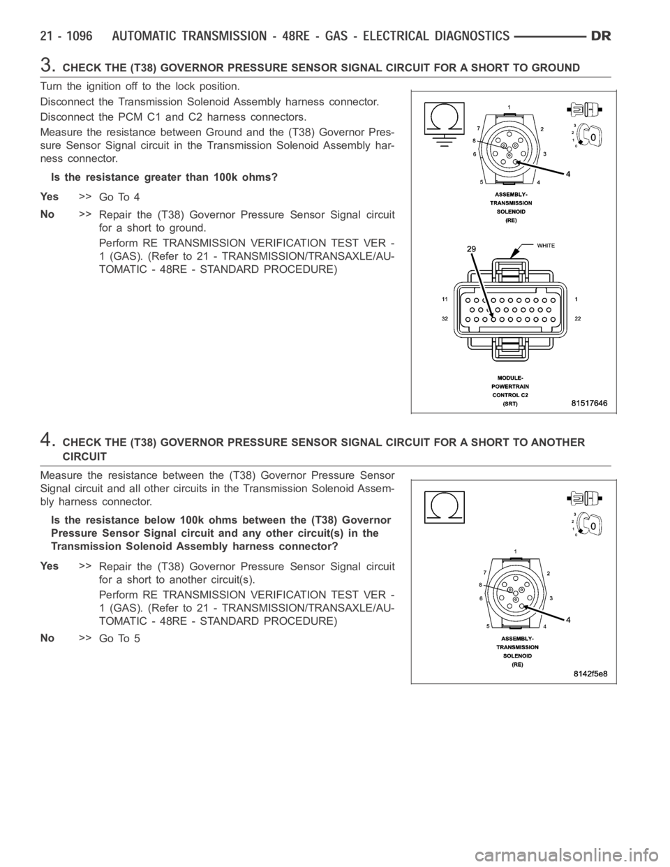
Disconnect the Transmission Solenoid Assembly harness connector.
Disconnect the PCM C1 and C2 harness connectors.
Measure the resistance between Ground and the (T38) Governor Pres-
sure Sensor Signal circuit in the Transmission Solenoid Assembly har-
ness connector.
Is the resistance greater than 100k ohms?
Ye s>>
Go To 4
No>>
Repair the (T38) Governor Pressure Sensor Signal circuit
for a short to ground.
Perform RE TRANSMISSION VERIFICATION TEST VER -
1 (GAS). (Refer to 21 - TRANSMISSION/TRANSAXLE/AU-
TOMATIC - 48RE - STANDARD PROCEDURE)
4.CHECK THE (T38) GOVERNOR PRESSURE SENSOR SIGNAL CIRCUIT FOR A SHORT TO ANOTHER
CIRCUIT
Measure the resistance between the (T38) Governor Pressure Sensor
Signal circuit and all other circuits in the Transmission Solenoid Assem-
bly harness connector.
Is the resistance below 100k ohms between the (T38) Governor
Pressure Sensor Signal circuit and any other circuit(s) in the
Transmission Solenoid Assembly harness connector?
Ye s>>
Repair the (T38) Governor Pressure Sensor Signal circuit
for a short to another circuit(s).
Perform RE TRANSMISSION VERIFICATION TEST VER -
1 (GAS). (Refer to 21 - TRANSMISSION/TRANSAXLE/AU-
TOMATIC - 48RE - STANDARD PROCEDURE)
No>>
Go To 5
Page 3618 of 5267
5.CHECK THE TRANSMISSION SOLENOID ASSEMBLY
Reconnect the Transmission Solenoid Assembly harness connector.
Remove the Transmission Oil Pan perthe Service Information. (Refer to
21 - TRANSMISSION/TRANSAXLE/AUTOMATIC - 48RE/FLUID -
STANDARD PROCEDURE)
Disconnect the Governor Pressure/Transmission Temperature Sensor
connector (inside transmission).
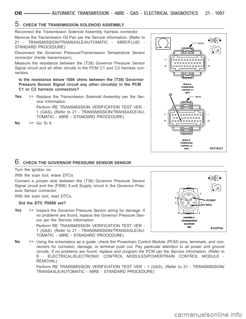
Measure the resistance between the (T38) Governor Pressure Sensor
Signal circuit and all other circuits in the PCM C1 and C2 harness con-
nectors.
Is the resistance below 100k ohms between the (T38) Governor
Pressure Sensor Signal circuit any other circuit(s) in the PCM
C1 or C2 harness connectors?
Ye s>>
Replace the Transmission Solenoid Assembly per the Ser-
vice Information.
Perform RE TRANSMISSION VERIFICATION TEST VER -
1 (GAS). (Refer to 21 - TRANSMISSION/TRANSAXLE/AU-
TOMATIC - 48RE - STANDARD PROCEDURE)
No>>
Go To 6
6.CHECK THE GOVERNOR PRESSURE SENSOR SENSOR
Turn the ignition on.
With the scan tool, erase DTCs.
Connect a jumper wire between the (T38) Governor Pressure Sensor
Signal circuit and the (F856) 5-volt Supply circuit in the Governor Pres-
sure Sensor connector.
With the scan tool, read DTCs.
Did the DTC P0868 set?
Ye s>>
Inspect the Governor Pressure Sensor wiring for damage. If
no problems are found, replace the Governor Pressure Sen-
sor per the Service Information.
Perform RE TRANSMISSION VERIFICATION TEST VER -
1 (GAS). (Refer to 21 - TRANSMISSION/TRANSAXLE/AU-
TOMATIC - 48RE - STANDARD PROCEDURE)
No>>
Using the schematics as a guide, check the Powertrain Control Module (PCM)pins, terminals, and con-
nectors for corrosion, damage, or terminal push out. Pay particular attention to all power and ground
circuits. If no problems are found, replace and program the PCM per the Service Information. (Refer to
8 - ELECTRICAL/ELECTRONIC CONTROL MODULES/POWERTRAIN CONTROL MODULE -
REMOVAL)
Perform RE TRANSMISSION VERIFICATION TEST VER - 1 (GAS). (Refer to 21 - TRANSMISSION/
TRANSAXLE/AUTOMATIC - 48RE - STANDARD PROCEDURE)
Page 3626 of 5267
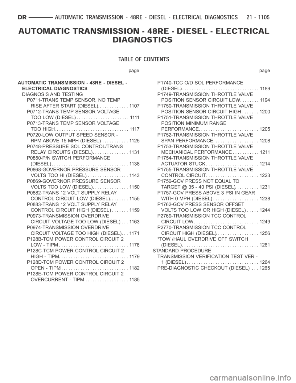
page page
AUTOMATIC TRANSMISSION - 48RE - DIESEL -
ELECTRICAL DIAGNOSTICS
DIAGNOSIS AND TESTING
P0711-TRANS TEMP SENSOR, NO TEMP
RISE AFTER START (DIESEL).............. 1107
P0712-TRANS TEMP SENSOR VOLTAGE
TOO LOW (DIESEL).......................1111
P0713-TRANS TEMP SENSOR VOLTAGE
TOO HIGH................................ 1117
P0720-LOW OUTPUT SPEED SENSOR -
RPM ABOVE 15 MPH (DIESEL)............ 1125
P0748-PRESSURE SOL CONTROL/TRANS
RELAY CIRCUITS (DIESEL)................ 1131
P0850-P/N SWITCH PERFORMANCE
(DIESEL)................................. 1138
P0868-GOVERNOR PRESSURE SENSOR
VOLTS TOO HI (DIESEL).................. 1143
P0869-GOVERNOR PRESSURE SENSOR
VOLTS TOO LOW (DIESEL)................ 1150
P0882-TRANS 12 VOLT SUPPLY RELAY
CONTROL CIRCUIT LOW (DIESEL)......... 1155
P0883-TRANS 12 VOLT SUPPLY RELAY
CONTROL CIRCUIT HIGH (DIESEL)........ 1159
P0973-TRANSMISSION OVERDRIVE
CIRCUIT VOLTAGE TOO LOW (DIESEL).... 1163
P0974-TRANSMISSION OVERDRIVE
CIRCUIT VOLTAGE TOO HIGH (DIESEL).... 1171
P128B-TCM POWER CONTROL CIRCUIT 2
LOW - TIPM.............................. 1176
P128C-TCM POWER CONTROL CIRCUIT 2
HIGH - TIPM.............................. 1179
P128D-TCM POWER CONTROL CIRCUIT 2
OPEN - TIPM............................. 1182
P128E-TCM POWER CONTROL CIRCUIT 2
OVERCURRENT - TIPM................... 1185P1740-TCC O/D SOL PERFORMANCE
(DIESEL)................................. 1189
P1749-TRANSMISSION THROTTLE VALVE
POSITION SENSOR CIRCUIT LOW......... 1194
P1750-TRANSMISSION THROTTLE VALVE
POSITION SENSOR CIRCUIT HIGH........ 1200
P1751-TRANSMISSION THROTTLE VALVE
POSITION MINIMUM RANGE
PERFORMANCE.......................... 1205
P1752-TRANSMISSION THROTTLE VALVE
SPAN PERFORMANCE.................... 1208
P1753-TRANSMISSION THROTTLE VALVE
MECHANICAL PERFORMANCE............ 1211
P1754-TRANSMISSION THROTTLE VALVE
ACTUATOR STUCK....................... 1214
P1755-TRANSMISSION THROTTLE VALVE
CONTROL CIRCUIT....................... 1223
P1756-GOV PRESS NOT EQUAL TO
TARGET @ 35 - 40 PSI (DIESEL)........... 1231
P1757-GOV PRESS ABOVE 3 PSI IN GEAR
WITH 0 MPH (DIESEL).................... 1238
P1762-GOV PRESS SENSOR OFFSET
VOLTS TOO LOW OR HIGH (DIESEL)...... 1244
P2769-TRANSMISSION TCC CONTROL
CIRCUIT LOW............................ 1249
P2770-TRANSMISSION TCC CONTROL
CIRCUIT HIGH (DIESEL).................. 1256
*TOW /HAUL OVERDRIVE OFF SWITCH
(DIESEL)................................. 1261
STANDARD PROCEDURE
TRANSMISSION VERIFICATION TEST VER -
1 (DIESEL)............................... 1264
PRE-DIAGNOSTIC CHECKOUT (DIESEL) . . . 1265
Page 3628 of 5267

P0711-TRANS TEMP SENSOR, NO TEMP RISE AFTER START (DIESEL)
For a complete wiring diagramRefer to Section 8W.
Page 3629 of 5267
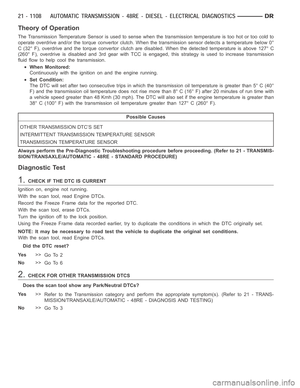
Theory of Operation
The Transmission Temperature Sensor is used to sense when the transmissiontemperatureistoohotortoocoldto
operate overdrive and/or the torque convertor clutch. When the transmission sensor detects a temperature below 0°
C (32° F), overdrive and the torque convertor clutch are disabled. When thedetected temperature is above 127° C
(260° F), overdrive is disabled and 3rd gear with TCC is engaged, this strategy is used to increase transmission
fluid flow to help cool the transmission.
When Monitored:
Continuously with the ignition on and the engine running.
Set Condition:
The DTC will set after two consecutive trips in which the transmission oil temperature is greater than 5° C (40°
F) and the transmission oil temperature does not rise more than 8° C (16° F) after 20 minutes of run time with
a vehicle speed greater than 48 Kmh (30 mph). The DTC will also set if the engine temperature is greater than
38° C (100° F) with the transmission oil temperature greater than 127° C (260° F).
Possible Causes
OTHER TRANSMISSION DTC’S SET
INTERMITTENT TRANSMISSION TEMPERATURE SENSOR
TRANSMISSION TEMPERATURE SENSOR
Always perform the Pre-Diagnostic Troubleshooting procedure before proceeding. (Refer to 21 - TRANSMIS-
SION/TRANSAXLE/AUTOMATIC - 48RE - STANDARD PROCEDURE)
Diagnostic Test
1.CHECK IF THE DTC IS CURRENT
Ignition on, engine not running.
With the scan tool, read Engine DTCs.
Record the Freeze Frame data for the reported DTC.
With the scan tool, erase DTCs.
Turn the ignition off to the lock position.
Using the Freeze Frame data recorded earlier, try to duplicate the conditions in which the DTC originally set.
NOTE: It may be necessary to road test the vehicle to duplicate the originalset conditions.
With the scan tool, read Engine DTCs.
Did the DTC reset?
Ye s>>
Go To 2
No>>
Go To 6
2.CHECK FOR OTHER TRANSMISSION DTCS
Does the scan tool show any Park/Neutral DTCs?
Ye s>>
Refer to the Transmission category and perform the appropriate symptom(s). (Refer to 21 - TRANS-
MISSION/TRANSAXLE/AUTOMATIC - 48RE - DIAGNOSIS AND TESTING)
No>>
Go To 3