Page 3630 of 5267
3.COMPARE THE TRANSMISSION TEMPERATURE TO ENGINE COOLANT TEMPERATURE
NOTE: To test the transmission temperature sensor, the engine and transmission temperature must be at or
below 29.4° C (85° F).
With the scan tool, read the Transmission and Engine temperatures.
Is the transmission temperature within 5° C (9° F) of the engine coolant temperature?
Ye s>>
Go To 4
No>>
Go To 5
4.CHECK IF THE TRANSMISSION TEMPERATURE INCREASES 15 DEGREES OVER 10 MINUTEPERIOD
NOTE: To test the transmission temperature sensor, the engine and transmission temperature must be at or
below 29.4° C (85° F).
CAUTION: Apply the parking brake.
Start the engine, firmly apply the brakes and allow the engine to idle in Drive.
With the scan tool, monitor the Transmission Temperature.
NOTE: If the transmission temperature sensor is working properly, the transmission temperature should rise
at least 8° C (15° F) within a ten minute period.
Did the transmission temperature increase at a steady rate and rise at least 8° C (15° F) over a 10
minute period?
Ye s>>
Go To 6
No>>
Go To 5
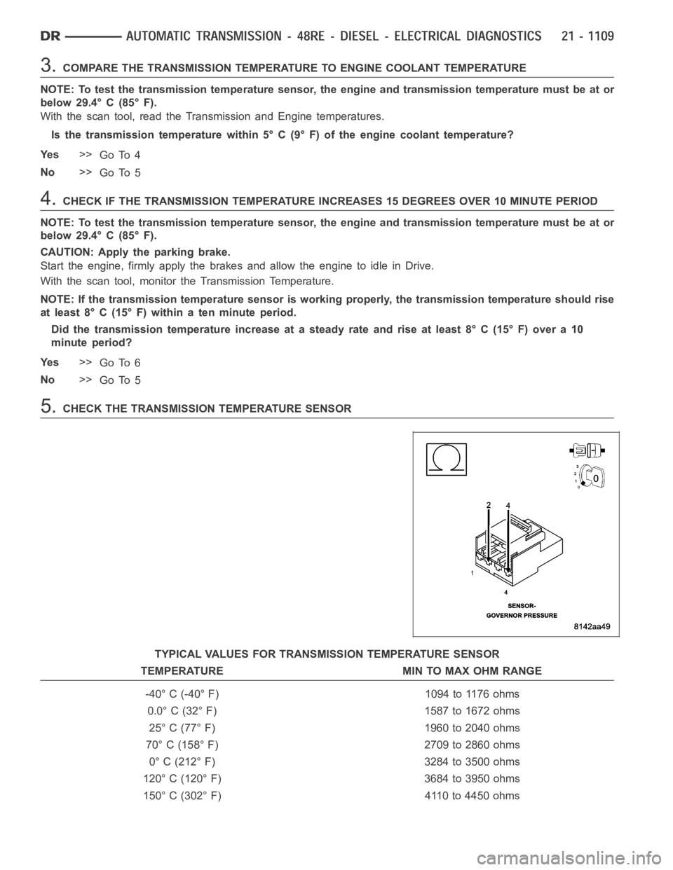
5.CHECK THE TRANSMISSION TEMPERATURE SENSOR
TYPICAL VALUES FOR TRANSMISSION TEMPERATURE SENSOR
TEMPERATURE MIN TO MAX OHM RANGE
-40° C (-40° F) 1094 to 1176 ohms
0.0° C (32° F) 1587 to 1672 ohms
25° C (77° F) 1960 to 2040 ohms
70° C (158° F) 2709 to 2860 ohms
0° C (212° F) 3284 to 3500 ohms
120° C (120° F) 3684 to 3950 ohms
150° C (302° F) 4110 to 4450 ohms
Page 3631 of 5267
Turn the ignition off to the lock position.
Remove the Transmission Oil Pan per the Service Information. (Refer to 21 -TRANSMISSION/TRANSAXLE/AU-
TOMATIC - 48RE/FLUID - STANDARD PROCEDURE)
Disconnect the Governor Pressure Sensor harness connector internal to the transmission.
NOTE: Check connectors - Clean/repair as necessary
Measure the resistance of the Transmission Temperature Sensor between the (T54) Transmission Temperature Sen-
sor Signal circuit and the (K900) Sensor Ground circuit.
Using the chart at the chart above, compare the Temperature Sensor temperature to the correlating resistance
value.
Is the resistance within the specified range when the sensor is at the giventemperature?
Ye s>>
Te s t C o m p l e t e .
No>>
Replace the Governor Pressure/Transmission Temperature Sensor per the Service Information. (Refer to
21 - TRANSMISSION/TRANSAXLE/AUTOMATIC - 48RE/GOVERNOR PRESSURE SENSOR-
REMOVAL)
Perform RE TRANSMISSION VERIFICATION TEST VER - 1 (DIESEL). (Refer to 21 - TRANSMISSION/
TRANSAXLE/AUTOMATIC - 48RE - STANDARD PROCEDURE)
6.INTERMITTENT WIRING AND CONNECTORS
The conditions necessary to set this DTC are not present at this time.
Use the Freeze Frame Data to help duplicate the conditions in which the DTC originally set. Pay particular attention
to the DTC set conditions, such as, VSS, MAP, ECT, and Load.
Using the schematics as a guide, visually inspect the related wiring harness. Look for any chafed, pierced, pinched,
or partially broken wires.
Visually inspect the related wiring harness connectors. Look for broken,bent, pushed out, or corroded terminals.
Wiggle the wiring and connectors while checking for any possible open or shorted circuits.
Check for any Service Information Tune-ups or Technical Service Bulletins that may apply.
Were there any problems found?
Ye s>>
Repair as necessary.
Perform RE TRANSMISSION VERIFICATION TEST VER - 1 (DIESEL). (Refer to 21 - TRANSMISSION/
TRANSAXLE/AUTOMATIC - 48RE - STANDARD PROCEDURE)
No>>
Te s t C o m p l e t e .
Page 3632 of 5267
P0712-TRANS TEMP SENSOR VOLTAGE TOO LOW (DIESEL)
For a complete wiring diagramRefer to Section 8W
Page 3633 of 5267
Theory of Operation
The Transmission Temperature Sensor is used to sense when the transmissiontemperatureistoohotortoocoldto
operate overdrive and/or the torque convertor clutch. When the transmission sensor detects a temperature below 0°
C (32° F), overdrive and the torque convertor clutch are disabled. When thedetected temperature is above 127° C
(260° F), overdrive is disabled and 3rd gear with TCC is engaged, this strategy is used to increase transmission
fluid flow to help cool the transmission.
When Monitored:
Continuously with the ignition on and the engine running.
Set Condition:
The DTC will set if the monitored Transmission Temperature Sensor Signal circuit drops below 1.55 volts for
the period of 2.25 seconds.
Possible Causes
(T54) TRANSMISSION TEMPERATURE SENSOR SIGNAL CIRCUIT SHORT TO GROUND
(T54) TRANSMISSION TEMPERATURE SENSOR SIGNAL CIRCUIT SHORT TO (K900) SENSOR GROUND
CIRCUIT
(T54) TRANSMISSION TEMPERATURE SENSOR SIGNAL CIRCUIT SHORT TO GROUND INSIDE
TRANSMISSION
(T54) TRANSMISSION TEMPERATURE SENSOR SIGNAL CIRCUIT SHORT TO THE (K900)SENSOR GROUND
CIRCUIT INSIDE TRANSMISSION
TRANSMISSION TEMPERATURE SENSOR
ENGINE CONTROL MODULE
Always perform the Pre-Diagnostic Troubleshooting procedure before proceeding. (Refer to 21 - TRANSMIS-
SION/TRANSAXLE/AUTOMATIC - 48RE - STANDARD PROCEDURE)
Diagnostic Test
1.CHECK IF THE DTC IS CURRENT
Ignition on, engine not running.
With the scan tool, read Engine DTCs.
Record the Freeze Frame data for the reported DTC.
With the scan tool, erase DTCs.
Turn the ignition off to the lock position.
Using the Freeze Frame data recorded earlier, try to duplicate the conditions in which the DTC originally set.
NOTE: It may be necessary to road test the vehicle to duplicate the originalset conditions.
With the scan tool, read Engine DTCs.
Did the DTC reset?
Ye s>>
Go To 2
No>>
Go To 8
Page 3634 of 5267
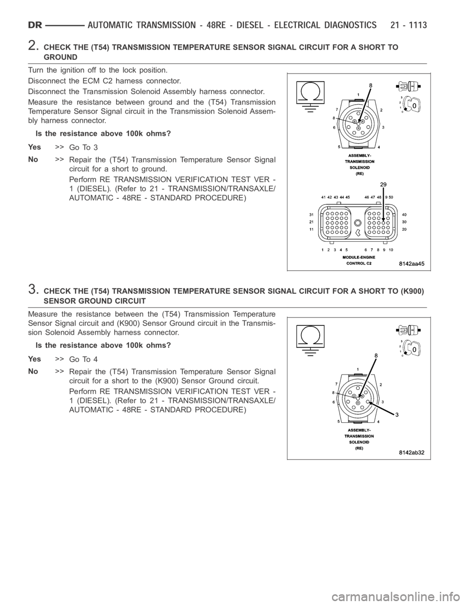
2.CHECK THE (T54) TRANSMISSION TEMPERATURE SENSOR SIGNAL CIRCUIT FOR A SHORTTO
GROUND
Turn the ignition off to the lock position.
Disconnect the ECM C2 harness connector.
Disconnect the Transmission Solenoid Assembly harness connector.
Measure the resistance between ground and the (T54) Transmission
Temperature Sensor Signal circuit in the Transmission Solenoid Assem-
bly harness connector.
Is the resistance above 100k ohms?
Ye s>>
Go To 3
No>>
Repair the (T54) Transmission Temperature Sensor Signal
circuit for a short to ground.
Perform RE TRANSMISSION VERIFICATION TEST VER -
1 (DIESEL). (Refer to 21 - TRANSMISSION/TRANSAXLE/
AUTOMATIC - 48RE - STANDARD PROCEDURE)
3.CHECK THE (T54) TRANSMISSION TEMPERATURE SENSOR SIGNAL CIRCUIT FOR A SHORT TO (K900)
SENSOR GROUND CIRCUIT
Measure the resistance between the (T54) Transmission Temperature
Sensor Signal circuit and (K900) Sensor Ground circuit in the Transmis-
sion Solenoid Assembly harness connector.
Is the resistance above 100k ohms?
Ye s>>
Go To 4
No>>
Repair the (T54) Transmission Temperature Sensor Signal
circuit for a short to the (K900) Sensor Ground circuit.
Perform RE TRANSMISSION VERIFICATION TEST VER -
1 (DIESEL). (Refer to 21 - TRANSMISSION/TRANSAXLE/
AUTOMATIC - 48RE - STANDARD PROCEDURE)
Page 3635 of 5267
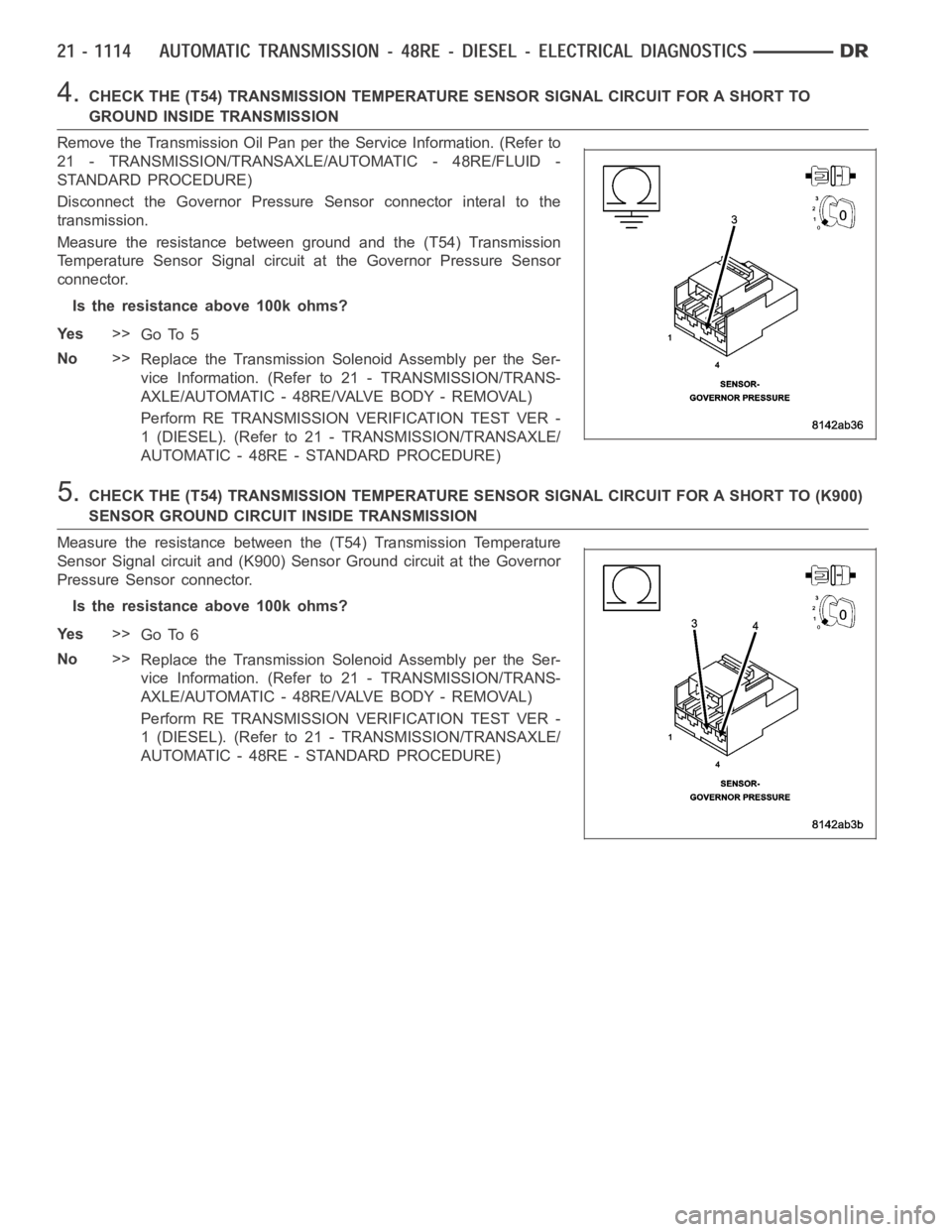
4.CHECK THE (T54) TRANSMISSION TEMPERATURE SENSOR SIGNAL CIRCUIT FOR A SHORTTO
GROUND INSIDE TRANSMISSION
Remove the Transmission Oil Pan perthe Service Information. (Refer to
21 - TRANSMISSION/TRANSAXLE/AUTOMATIC - 48RE/FLUID -
STANDARD PROCEDURE)
Disconnect the Governor Pressure Sensor connector interal to the
transmission.
Measure the resistance between ground and the (T54) Transmission
Temperature Sensor Signal circuit at the Governor Pressure Sensor
connector.
Is the resistance above 100k ohms?
Ye s>>
Go To 5
No>>
Replace the Transmission Solenoid Assembly per the Ser-
vice Information. (Refer to 21 - TRANSMISSION/TRANS-
AXLE/AUTOMATIC - 48RE/VALVE BODY - REMOVAL)
Perform RE TRANSMISSION VERIFICATION TEST VER -
1 (DIESEL). (Refer to 21 - TRANSMISSION/TRANSAXLE/
AUTOMATIC - 48RE - STANDARD PROCEDURE)
5.CHECK THE (T54) TRANSMISSION TEMPERATURE SENSOR SIGNAL CIRCUIT FOR A SHORT TO (K900)
SENSOR GROUND CIRCUIT INSIDE TRANSMISSION
Measure the resistance between the (T54) Transmission Temperature
Sensor Signal circuit and (K900) Sensor Ground circuit at the Governor
Pressure Sensor connector.
Is the resistance above 100k ohms?
Ye s>>
Go To 6
No>>
Replace the Transmission Solenoid Assembly per the Ser-
vice Information. (Refer to 21 - TRANSMISSION/TRANS-
AXLE/AUTOMATIC - 48RE/VALVE BODY - REMOVAL)
Perform RE TRANSMISSION VERIFICATION TEST VER -
1 (DIESEL). (Refer to 21 - TRANSMISSION/TRANSAXLE/
AUTOMATIC - 48RE - STANDARD PROCEDURE)
Page 3636 of 5267
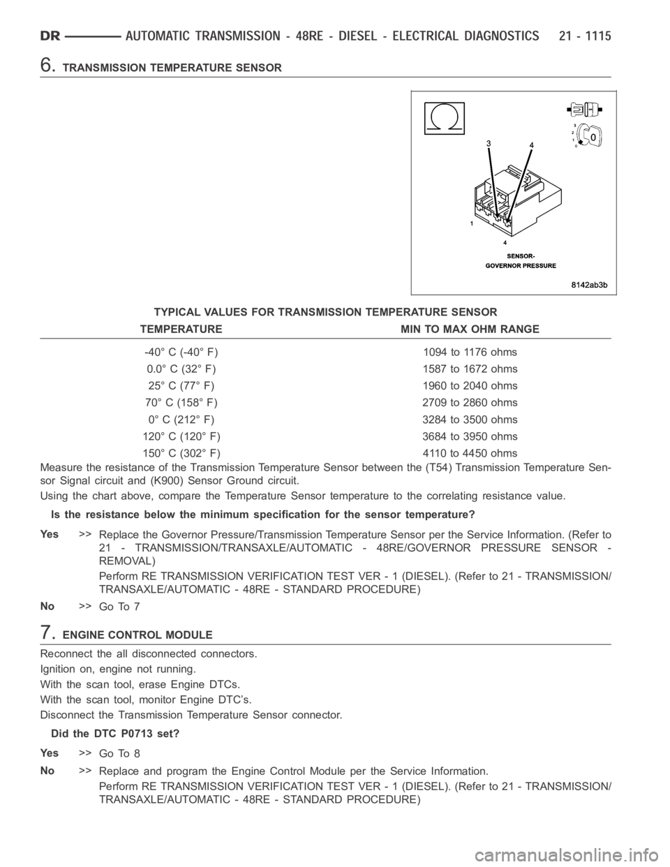
6.TRANSMISSION TEMPERATURE SENSOR
TYPICAL VALUES FOR TRANSMISSION TEMPERATURE SENSOR
TEMPERATURE MIN TO MAX OHM RANGE
-40° C (-40° F) 1094 to 1176 ohms
0.0° C (32° F) 1587 to 1672 ohms
25° C (77° F) 1960 to 2040 ohms
70° C (158° F) 2709 to 2860 ohms
0° C (212° F) 3284 to 3500 ohms
120° C (120° F) 3684 to 3950 ohms
150° C (302° F) 4110 to 4450 ohms
Measure the resistance of the Transmission Temperature Sensor between the (T54) Transmission Temperature Sen-
sor Signal circuit and (K900) Sensor Ground circuit.
Using the chart above, compare the Temperature Sensor temperature to the correlating resistance value.
Is the resistance below the minimum specification for the sensor temperature?
Ye s>>
Replace the Governor Pressure/Transmission Temperature Sensor per the Service Information. (Refer to
21 - TRANSMISSION/TRANSAXLE/AUTOMATIC - 48RE/GOVERNOR PRESSURE SENSOR-
REMOVAL)
Perform RE TRANSMISSION VERIFICATION TEST VER - 1 (DIESEL). (Refer to 21 - TRANSMISSION/
TRANSAXLE/AUTOMATIC - 48RE - STANDARD PROCEDURE)
No>>
Go To 7
7.ENGINE CONTROL MODULE
Reconnect the all disconnected connectors.
Ignition on, engine not running.
With the scan tool, erase Engine DTCs.
With the scan tool, monitor Engine DTC’s.
Disconnect the Transmission Temperature Sensor connector.
Did the DTC P0713 set?
Ye s>>
Go To 8
No>>
Replace and program the Engine Control Module per the Service Information.
Perform RE TRANSMISSION VERIFICATION TEST VER - 1 (DIESEL). (Refer to 21 - TRANSMISSION/
TRANSAXLE/AUTOMATIC - 48RE - STANDARD PROCEDURE)
Page 3638 of 5267
P0713-TRANS TEMP SENSOR VOLTAGE TOO HIGH
For a complete wiring diagramRefer to Section 8W