2006 DODGE RAM SRT-10 ignition
[x] Cancel search: ignitionPage 2894 of 5267
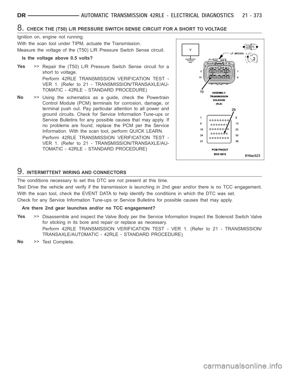
8.CHECK THE (T50) L/R PRESSURE SWITCH SENSE CIRCUIT FOR A SHORT TO VOLTAGE
Ignition on, engine not running.
With the scan tool under TIPM, actuate the Transmission.
Measure the voltage of the (T50) L/R Pressure Switch Sense circuit.
Is the voltage above 0.5 volts?
Ye s>>
Repair the (T50) L/R PressureSwitch Sense circuit for a
short to voltage.
Perform 42RLE TRANSMISSION VERIFICATION TEST -
VER 1. (Refer to 21 - TRANSMISSION/TRANSAXLE/AU-
TOMATIC - 42RLE - STANDARD PROCEDURE)
No>>
Using the schematics as a guide, check the Powertrain
Control Module (PCM) terminals for corrosion, damage, or
terminal push out. Pay particular attention to all power and
ground circuits. Check for Service Information Tune-ups or
Service Bulletins for any possible causes that may apply. If
no problems are found, replace the PCM per the Service
Information. With the scan tool, perform QUICK LEARN.
Perform 42RLE TRANSMISSION VERIFICATION TEST -
VER 1. (Refer to 21 - TRANSMISSION/TRANSAXLE/AU-
TOMATIC - 42RLE - STANDARD PROCEDURE)
9.INTERMITTENT WIRING AND CONNECTORS
The conditions necessary to set this DTC are not present at this time.
Test Drive the vehicle and verify if the transmission is launching in 2nd gear and/or there is no TCC engagement.
With the scan tool, check the EVENT DATAto help identify the conditions in which the DTC was set.
Check for any Service Information Tune-ups or Service Bulletins for possible causes that may apply.
Are there 2nd gear launches and/or no TCC engagement?
Ye s>>
Disassemble and inspect the Valve Body per the Service Information Inspect the Solenoid Switch Valve
for sticking in its bore and repair or replace as necessary.
Perform 42RLE TRANSMISSION VERIFICATION TEST - VER 1. (Refer to 21 - TRANSMISSION/
TRANSAXLE/AUTOMATIC - 42RLE - STANDARD PROCEDURE)
No>>
Te s t C o m p l e t e .
Page 2897 of 5267
When Monitored:
Every 7msec after a controller reset with transmission in neutral.
Set Condition:
After a PCM reset in neutral and Input and Output sensor ratio equals 2.50 to1.0 ± 50.0 RPM.
Possible Causes
SPEED SENSOR GROUND CIRCUIT OPEN
POWERTRAIN CONTROL MODULE
Always perform the 42RLE Pre-Diagnostic Troubleshooting procedure before proceeding. (Refer to 21 -
TRANSMISSION/TRANSAXLE/AUTOMATIC - 42RLE - STANDARD PROCEDURE)
Theory of Operation
The input and output speed sensors use a common ground circuit. The loss of this common ground results in the
input signal being sensed for both. After a reset in neutral, and after observing a specific ratio, the Speed Check
Fault Counter will increment. Because the speed sensors and the thermistor share the same ground circuit, this
DTC may indicate a loss of the common speed sensor ground. In some cases thisfault will cause a Gear Ratio
Error DTC to be set.
Diagnostic Test
1.PCM AND WIRING
Turn the ignition off to the lock position.
Remove the Ignition Switch Feed fuse from the TIPM.
CAUTION: Removal of the Ignition Switch Feed fuse from the TIPM will prevent the vehicle from being
startedingear.
WARNING: The Ignition Switch Feed fuse must be removed from the TIPM. Failure to do so can result in
personal injury or death.
Install the Transmission Simulator,Miller tool #8333 and the ElectronicTransmission Adapter kit 8333-1A.
Ignition on, engine not running.
With the Transmission Simulator, set the
Input/Output Speedswitch toONand the rotary switch to the3000/
1250
position.
With the scan tool, monitor the Input and Output Speed Sensor readings.
Does the Input Speed read 3000 RPM and the Output Speed read 1250 RPM, ± 50 RPM?
Ye s>>
Go To 2
No>>
Go To 3
Page 2898 of 5267

2.(T13) SPEED SENSOR GROUND CIRCUIT OPEN
Turn the ignition off to the lock position.
Disconnect the PCM C4 harness connector.
Disconnect the Input and Output Speed Sensor harness connectors.
CAUTION: Do not probe the PCM harness connectors. Probing the
PCM harness connectors will damage the PCM terminals resulting
in poor terminal to pin connection. Install Miller tool #8815 to per-
form diagnosis.
Measure the resistance of both of the (T13) Speed Sensor Ground cir-
cuits from the appropriate terminal of special tool #8815 to the Input
and Output Speed Sensor harness connectors.
Is the resistance above 5.0 ohms on either circuit?
Ye s>>
Repair the (T13) Speed Sensor Ground circuit for an open.
Perform 42RLE TRANSMISSION VERIFICATION TEST -
VER 1. (Refer to 21 - TRANSMISSION/TRANSAXLE/AU-
TOMATIC - 42RLE - STANDARD PROCEDURE)
No>>
Using the schematics as a guide, check the Powertrain
Control Module (PCM) terminals for corrosion, damage, or
terminal push out. Pay particular attention to all power and
ground circuits. If no problems are found, replace the PCM
per the Service Information.With the scan tool, perform
QUICK LEARN
Perform 42RLE TRANSMISSION VERIFICATION TEST - VER 1. (Refer to 21 - TRANSMISSION/
TRANSAXLE/AUTOMATIC - 42RLE - STANDARD PROCEDURE)
3.INTERMITTENT WIRING AND CONNECTORS
The conditions necessary to set the DTC are not present at this time.
Using the schematics as a guide, inspect the wiring and connectors specifictothiscircuit.
Wiggle the wires while checking for shorted and open circuits.
With the scan tool, check the DTC EVENT DATA to help identify the conditionsin which the DTC was set.
Were there any problems found?
Ye s>>
Repair as necessary.
Perform 42RLE TRANSMISSION VERIFICATION TEST - VER 1. (Refer to 21 - TRANSMISSION/
TRANSAXLE/AUTOMATIC - 42RLE - STANDARD PROCEDURE)
No>>
Te s t C o m p l e t e .
Page 2908 of 5267
STANDARD PROCEDURE
PRE-DIAGNOSTIC TROUBLESHOOTING PROCEDURE - 42RLE
For a complete wiring diagramRefer to Section 8W.
1.
Perform the following steps prior to any diagnostic procedure:
Many transmission symptoms can be caused by a low fluid level. If the fluid level is low, locate and repair any
leaks and fill the transmission to the proper fluid level. Refer to the Service Information for the proper repair
and fluid fill procedures.
Testing should only be performed with the battery fully charged to avoid false diagnosis.
With the scan tool, read Engine (PCM) DTCs. If Engine DTCs are present, refer to the Driveability Category
and perform to the appropriate diagnostic procedure(s) before proceeding.
With the scan tool, read Transmission (TCM) DTCs. Record all Stored, Active, and Pending DTC information.
Diagnose any Pending DTC as a matured DTC.
With the scan tool, read DTC EVENT DATA.Use this data to identify the conditions in which the DTC was set.
Note: Performing a Battery Disconnect will clear all DTC EVENT DATA and reset all learned Transmis-
sion values to the controllers default values, which may temporarily result in erratic shift schedules.
With the scan tool, perform the Shift Lever Position Test. If the test does not pass, refer to the diagnostic
procedure for P0706-Check Shifter Signal.
For Gear Ratio Error DTCs, use the scan tool to read and record the Clutch Volume Index (CVI) information.
Use the wiring diagram as a guide, inspect the wiring and connectors related to this circuit and repair as nec-
essary.
Refer to the When Monitored and Set Conditions for this DTC. DTCs can set at ignition on, at start up, driving
under specific conditions, and after controller diagnostic monitors haverun.
Refer to applicable Technical Service Bulletins (TSBs) for controller software update information. Some condi-
tions can be corrected by upgrading the Engine (PCM) or Transmission (TCM)controller software.
Check for any Service Information Tune-ups or Service Bulletins for any possible causes that may apply.
Were there any repairs made that fixed the vehicle?
Ye s>>
Testing complete.
Perform 42RLE VERIFICATION TEST - VER1(Referto21-TRANSMISSION/TRANSAXLE/AUTO-
MATIC - 42RLE - STANDARD PROCEDURE)
No>>
Refer to the Transmission category and perform the appropriate diagnostic procedure(s). (Refer to 21 -
TRANSMISSION/TRANSAXLE/AUTOMATIC - 42RLE - DIAGNOSIS AND TESTING)
Page 3010 of 5267
MECHANISM-BRAKE TRANSMISSION SHIFT INTERLOCK
DESCRIPTION
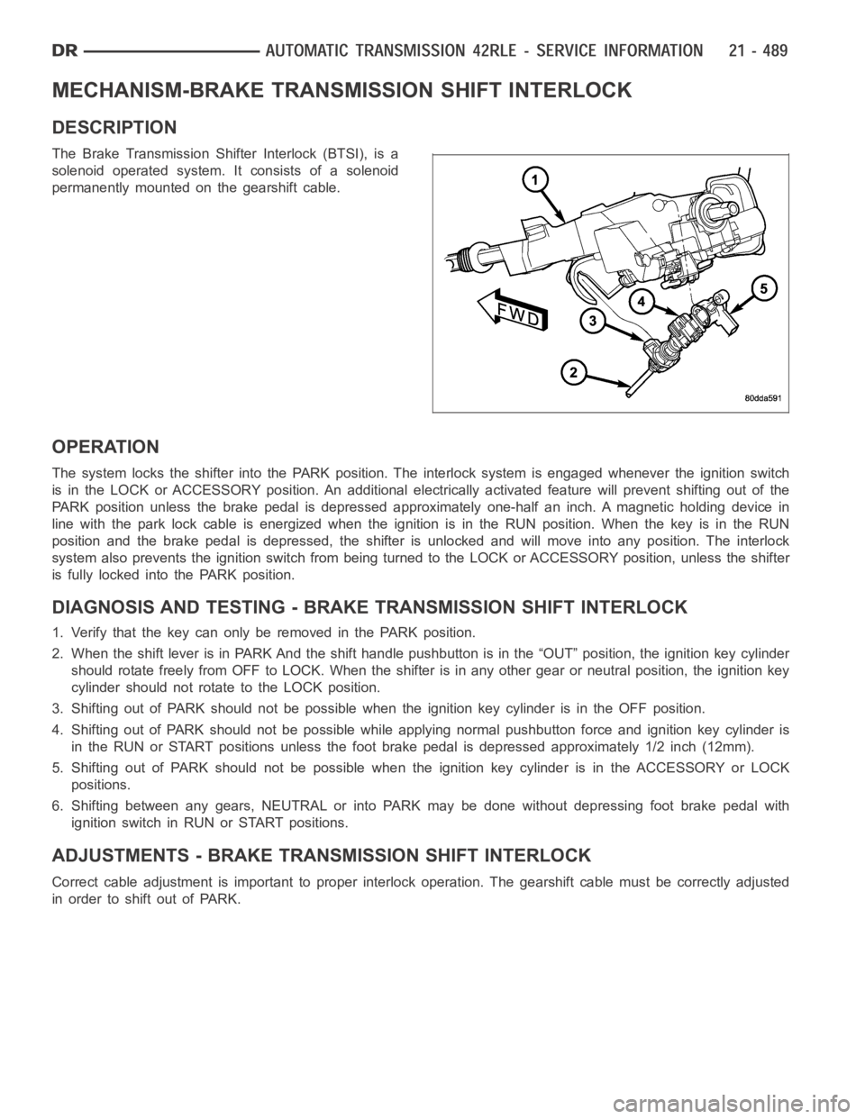
The Brake Transmission Shifter Interlock (BTSI), is a
solenoid operated system. It consists of a solenoid
permanently mounted on the gearshift cable.
OPERATION
The system locks the shifter into the PARK position. The interlock system is engaged whenever the ignition switch
is in the LOCK or ACCESSORY position. An additional electrically activated feature will prevent shifting out of the
PARK position unless the brake pedal is depressed approximately one-halfan inch. A magnetic holding device in
line with the park lock cable is energized when the ignition is in the RUN position. When the key is in the RUN
position and the brake pedal is depressed, the shifter is unlocked and willmove into any position. The interlock
system also prevents the ignition switch from being turned to the LOCK or ACCESSORY position, unless the shifter
is fully locked into the PARK position.
DIAGNOSIS AND TESTING - BRAKE TRANSMISSION SHIFT INTERLOCK
1. Verify that the key can only be removed in the PARK position.
2. When the shift lever is in PARK And the shift handle pushbutton is in the “OUT” position, the ignition key cylinder
should rotate freely from OFF to LOCK. When the shifter is in any other gear or neutral position, the ignition key
cylinder should not rotate to the LOCK position.
3. Shifting out of PARK should not be possible when the ignition key cylinder is in the OFF position.
4. Shifting out of PARK should not be possible while applying normal pushbutton force and ignition key cylinder is
in the RUN or START positions unless the foot brake pedal is depressed approximately 1/2 inch (12mm).
5. Shifting out of PARK should not be possible when the ignition key cylinderisintheACCESSORYorLOCK
positions.
6. Shifting between any gears, NEUTRAL or into PARK may be done without depressing foot brake pedal with
ignition switch in RUN or START positions.
ADJUSTMENTS - BRAKE TRANSMISSION SHIFT INTERLOCK
Correct cable adjustment is important to proper interlock operation. Thegearshift cable must be correctly adjusted
in order to shift out of PARK.
Page 3011 of 5267
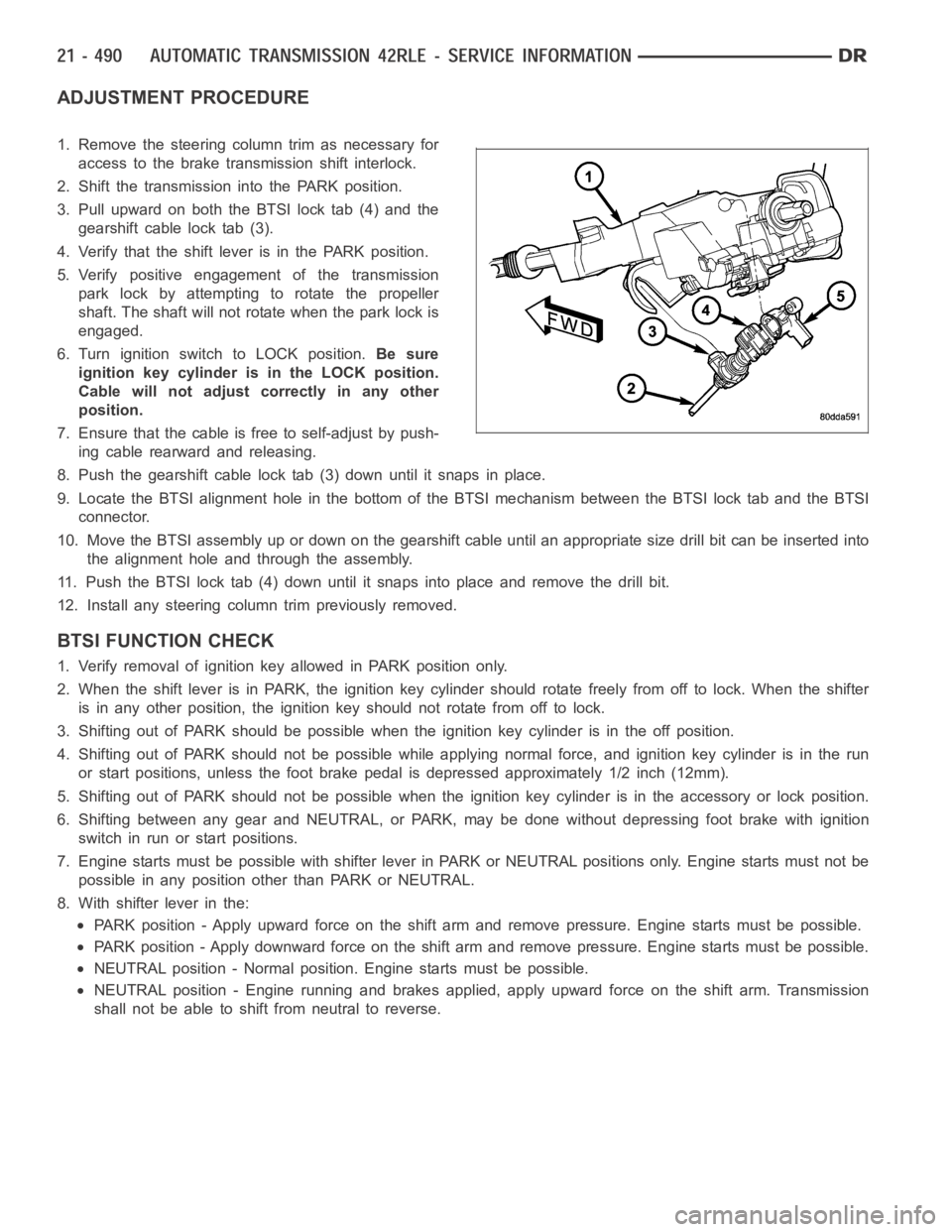
ADJUSTMENT PROCEDURE
1. Remove the steering column trim as necessary for
access to the brake transmission shift interlock.
2. Shift the transmission into the PARK position.
3. Pull upward on both the BTSI lock tab (4) and the
gearshift cable lock tab (3).
4. Verify that the shift lever is in the PARK position.
5. Verify positive engagement of the transmission
park lock by attempting to rotate the propeller
shaft. The shaft will not rotate when the park lock is
engaged.
6. Turn ignition switch to LOCK position.Be sure
ignition key cylinder is in the LOCK position.
Cable will not adjust correctly in any other
position.
7. Ensure that the cable is free to self-adjust by push-
ing cable rearward and releasing.
8. Push the gearshift cable lock tab (3) down until it snaps in place.
9. Locate the BTSI alignment hole in the bottom of the BTSI mechanism betweentheBTSIlocktabandtheBTSI
connector.
10. Move the BTSI assembly up or down on the gearshift cable until an appropriate size drill bit can be inserted into
the alignment hole and through the assembly.
11. Push the BTSI lock tab (4) down until it snaps into place and remove the drill bit.
12. Install any steering column trim previously removed.
BTSI FUNCTION CHECK
1. Verify removal of ignition key allowed in PARK position only.
2. When the shift lever is in PARK, the ignition key cylinder should rotate freely from off to lock. When the shifter
is in any other position, the ignition key should not rotate from off to lock.
3. Shifting out of PARK should be possible when the ignition key cylinder isin the off position.
4. Shifting out of PARK should not be possible while applying normal force,and ignition key cylinder is in the run
or start positions, unless the foot brake pedal is depressed approximately1/2inch(12mm).
5. Shifting out of PARK should not be possible when the ignition key cylinder is in the accessory or lock position.
6. Shifting between any gear and NEUTRAL, or PARK, may be done without depressing foot brake with ignition
switch in run or start positions.
7. Engine starts must be possible with shifter lever in PARK or NEUTRAL positions only. Engine starts must not be
possible in any position other than PARK or NEUTRAL.
8. With shifter lever in the:
PARK position - Apply upward force on the shift arm and remove pressure. Enginestartsmustbepossible.
PARK position - Apply downward force on the shift arm and remove pressure. Engine starts must be possible.
NEUTRAL position - Normal position. Engine starts must be possible.
NEUTRAL position - Engine running and brakes applied, apply upward force on the shift arm. Transmission
shall not be able to shift from neutral to reverse.
Page 3071 of 5267
SWITCH-TOW/HAUL OVERDRIVE
DESCRIPTION
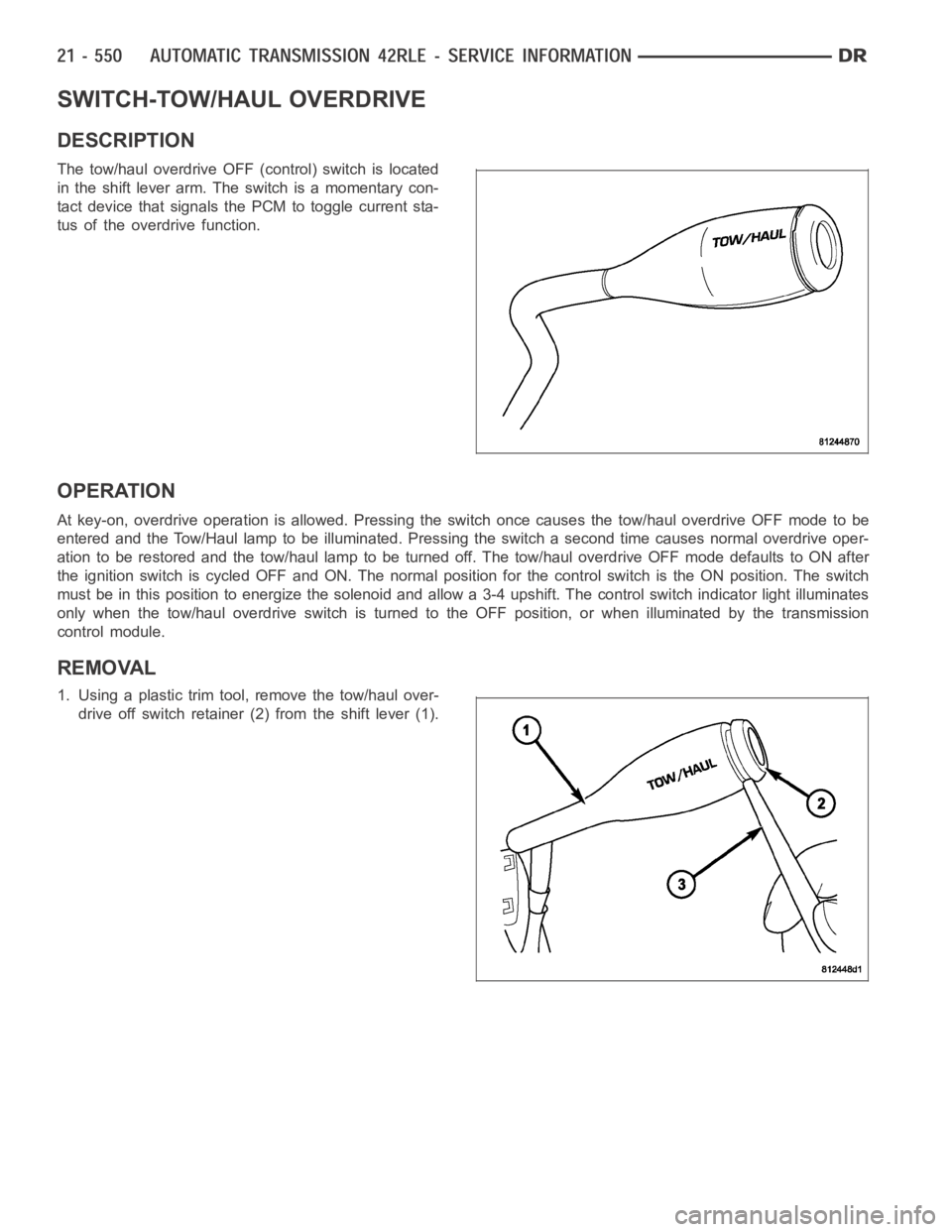
The tow/haul overdrive OFF (control) switch is located
in the shift lever arm. The switch is a momentary con-
tact device that signals the PCM to toggle current sta-
tus of the overdrive function.
OPERATION
At key-on, overdrive operation is allowed. Pressing the switch once causes the tow/haul overdrive OFF mode to be
entered and the Tow/Haul lamp to be illuminated. Pressing the switch a second time causes normal overdrive oper-
ationtoberestoredandthetow/haullamptobeturnedoff.Thetow/hauloverdrive OFF mode defaults to ON after
the ignition switch is cycled OFF and ON. The normal position for the control switch is the ON position. The switch
must be in this position to energize the solenoid and allow a 3-4 upshift. The control switch indicator light illuminates
only when the tow/haul overdrive switch is turned to the OFF position, or when illuminated by the transmission
control module.
REMOVAL
1. Using a plastic trim tool, remove the tow/haul over-
drive off switch retainer (2) from the shift lever (1).
Page 3103 of 5267
P0122-TPS/APP CIRCUIT LOW
For a complete wiring diagramRefer to Section 8W.
Theory of Operation
Due to the integration of the Powertrain and Transmission Control Modulesthe New Generation Control Module III
will be referred to as the Powertrain Control Module (PCM). The 3–wire TPS (4.7L V-8 Engine) provides the PCM
with an input signal voltage that represents the throttle blade position of the throttle body. The Throttle Position
Sensor (TPS) is connected to the throttle blade shaft. As the position of the throttle blade changes, the output volt-
age of the TPS changes.
The PCM supplies approximately 5.0 volts to the TPS. The TPS output voltage(input signal to the PCM) represents
the throttle blade position. The PCM receives an input signal voltage fromthe TPS. This will vary in an approximate
range from 0.26 volts at minimum throttle opening (idle), to 4.49 volts at maximum opening (wide open throttle).
The Accelerator Pedal Position Sensor (APPS) is currently used only with the 5.7L V-8 engine. The APPS is a linear
potentiometer. It provides the PCM with a voltage signal proportional to the angle, or position of the accelerator
pedal. The APPS signal along with inputs from other sensors is used by the PCM to calculate the throttle plate
position.
A mechanical cable is used between the accelerator pedal and the APPS assembly. Although a cable is used
between the accelerator pedal and the APPS assembly, a mechanical cable isnot used between the accelerator
pedal and the throttle body. The throttle plate position is electronically controlled by the PCM.
When Monitored:
Continuously with the ignition on and engine running.
Set Condition:
This DTC will set if the monitored TPS voltage drops below .078 volts for theperiod of 0.48 seconds.
Possible Causes
RELATED ENGINE TPS/APPS DTC’S PRESENT
POWERTRAIN CONTROL MODULE
Always perform the Pre-Diagnostic Troubleshooting procedure before proceeding. (Refer to 21 - TRANSMIS-
SION/TRANSAXLE/AUTOMATIC - 45RFE/545RFE - STANDARD PROCEDURE)
Diagnostic Test
1.CHECK IF RELATED ENGINE TPS/APPS DTC’S ARE PRESENT
With the scan tool, check Engine DTC’s.
Are there any Engine TPS/APPS DTCs present?
Ye s>>
Refer to the Driveability Category and perform the appropriate Symptom.
No>>
Go To 2
2.CHECK TO SEE IF DTC IS CURRENT
With the scan tool, record the DTC EVENT DATA to help identify the conditionsinwhichtheDTCwasset.
With the scan tool, erase Transmission DTCs.
NOTE: To erase DTC EVENT DATA information, a BATTERY DISCONNECT must be performed. Performing a
BATTERY DISCONNECT may reset learned Transmission values to controller defaults which may lead to
erratic shift schedules.
Drive the vehicle and try to duplicate the conditions in which the DTC was reported by the DTC EVENT DATA.