Page 4356 of 5267
INSTALLATION
1. Position the tailgate check cable (2) onto the left
and right side of the tailgate (3) as necessary.
2. Install the bolt (1) that secures the small end of the
tailgate check cable(s) to the tailgate. Tighten the
bolt(s) to 23 Nꞏm (17 ft. lbs.).
3. Position the tailgate check cable (3) to the left and
right side of the cargo box below the tailgate striker
(1) as necessary.
4. Install the large end of the tailgate check cable(s)
onto the cargo box. Make sure that the cable lock
tab(s) (4) fully engage.
Page 4365 of 5267

page page
DOOR
REMOVAL .................................... 29
INSTALLATION ............................... 29
ADJUSTMENTS ............................... 29
DOOR GLASS
REMOVAL .................................... 34
INSTALLATION ............................... 35
EXTERIOR HANDLE
REMOVAL .................................... 36
INSTALLATION ............................... 36
GLASS RUN CHANNEL
REMOVAL
FRONT-ALL MODELS ....................... 37
REAR-QUAD CAB ........................... 37
REAR-STANDARD CAB ..................... 38
INSTALLATION
FRONT-ALL MODELS ....................... 38
REAR-QUAD CAB ........................... 39
REAR-STANDARD CAB ..................... 39
HINGE
REMOVAL .................................... 40
INSTALLATION ............................... 40
INTERIOR HANDLE ACTUATOR
REMOVAL .................................... 41
INSTALLATION ............................... 41
LATCH
REMOVAL .................................... 42INSTALLATION ............................... 43
ADJUSTMENTS ............................... 44
LATCH STRIKER
REMOVAL .................................... 45
INSTALLATION ............................... 45
ADJUSTMENTS ............................... 46
LOCK CYLINDER
REMOVAL .................................... 47
INSTALLATION ............................... 47
TRIM PANEL
REMOVAL .................................... 48
INSTALLATION ............................... 49
WATERDAM
REMOVAL .................................... 50
INSTALLATION ............................... 50
WINDOW REGULATOR - POWER
REMOVAL .................................... 51
INSTALLATION ............................... 52
WINDOW REGULATOR - MANUAL
REMOVAL .................................... 53
INSTALLATION ............................... 54
SIDE VIEW MIRROR FLAG
REMOVAL .................................... 55
INSTALLATION ............................... 55
Page 4384 of 5267
LOCK CYLINDER
REMOVAL
1. Remove the exterior door handle (1) (Refer to 23 -
BODY/DOOR - FRONT/EXTERIOR HANDLE -
REMOVAL).
2. Remove the clip (3) that secures the lock cylinder
lever (5) and the electric lock switch (4), if
equipped, to the door lock cylinder (6).
3. Remove the screw (2) that secures the door lock
cylinder to the exterior handle and remove the lock
cylinder.
INSTALLATION
1. Position the door lock cylinder (6) into the exterior
door handle (1).
2. Install the screw (2) that secures the door lock cyl-
inder to the exterior door handle. Tighten the screw
securely.
3. Install the electric lock switch (4), if equipped, and
the lock cylinder lever (5) to the door lock cylinder.
4. Install the clip (3) that secures the lock cylinder
lever and the electric lock switch, if equipped, to
the door lock cylinder.
5. Install the exterior door handle (Refer to 23 -
BODY/DOOR - FRONT/EXTERIOR HANDLE -
INSTALLATION).
Page 4424 of 5267

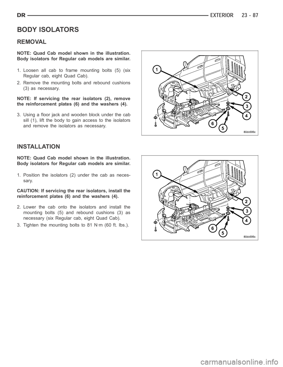
BODY ISOLATORS
REMOVAL
NOTE: Quad Cab model shown in the illustration.
Body isolators for Regular cab models are similar.
1. Loosen all cab to frame mounting bolts (5) (six
Regular cab, eight Quad Cab).
2. Remove the mounting bolts and rebound cushions
(3) as necessary.
NOTE: If servicing the rear isolators (2), remove
the reinforcement plates (6) and the washers (4).
3. Using a floor jack and wooden block under the cab
sill (1), lift the body to gain access to the isolators
and remove the isolators as necessary.
INSTALLATION
NOTE: Quad Cab model shown in the illustration.
Body isolators for Regular cab models are similar.
1. Position the isolators (2) under the cab as neces-
sary.
CAUTION: If servicing the rear isolators, install the
reinforcement plates (6) and the washers (4).
2. Lower the cab onto the isolators and install the
mounting bolts (5) and rebound cushions (3) as
necessary (six Regular cab, eight Quad Cab).
3. Tighten the mounting bolts to 81 Nꞏm (60 ft. lbs.).
Page 4508 of 5267
4. Remove the screws and remove the knee blocker.
INSTALLATION
1. Install the knee blocker (2) and install the screws
(1).
Page 4564 of 5267
INSTALLATION
NOTE: Free pivot hinge cover is installed with the
free pivot hinge (Refer to 23 - BODY/SEATS/CEN-
TER SEAT BACK HINGE - INSTALLATION).
1. Position the hinge cover (1) over the hinge (2) and
close over the lock tabs (3).
2. Install the pivot bolt (5) and tighten to 10 Nꞏm (89
in. lbs.).
3. Reposition the storage bin/cushion cover (4).
4. Connect the zip strip (1).
Page 4601 of 5267

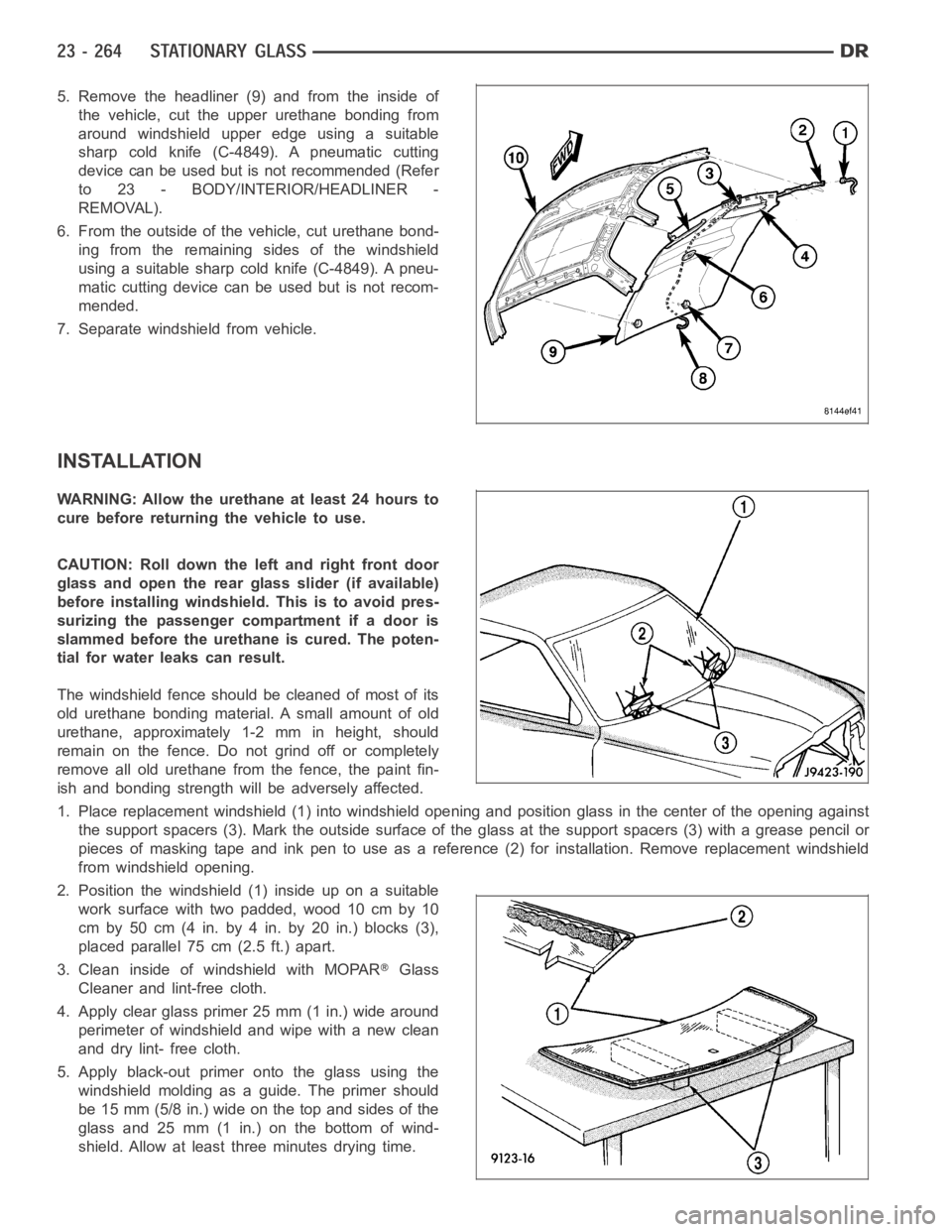
5. Remove the headliner (9) and from the inside of
the vehicle, cut the upper urethane bonding from
around windshield upper edge using a suitable
sharp cold knife (C-4849). A pneumatic cutting
device can be used but is not recommended (Refer
to 23 - BODY/INTERIOR/HEADLINER -
REMOVAL).
6. From the outside of the vehicle, cut urethane bond-
ing from the remaining sides of the windshield
using a suitable sharp cold knife (C-4849). A pneu-
matic cutting device can be used but is not recom-
mended.
7. Separate windshield from vehicle.
INSTALLATION
WARNING: Allow the urethane at least 24 hours to
cure before returning the vehicle to use.
CAUTION: Roll down the left and right front door
glass and open the rear glass slider (if available)
before installing windshield. This is to avoid pres-
surizing the passenger compartment if a door is
slammed before the urethane is cured. The poten-
tial for water leaks can result.
The windshield fence should be cleaned of most of its
old urethane bonding material. A small amount of old
urethane, approximately 1-2 mm in height, should
remain on the fence. Do not grind off or completely
remove all old urethane from the fence, the paint fin-
ish and bonding strength will be adversely affected.
1. Place replacement windshield (1) into windshield opening and positionglass in the center of the opening against
the support spacers (3). Mark the outside surface of the glass at the support spacers (3) with a grease pencil or
pieces of masking tape and ink pen to use as a reference (2) for installation. Remove replacement windshield
from windshield opening.
2. Position the windshield (1) inside up on a suitable
work surface with two padded, wood 10 cm by 10
cm by 50 cm (4 in. by 4 in. by 20 in.) blocks (3),
placed parallel 75 cm (2.5 ft.) apart.
3. Clean inside of windshield with MOPAR
Glass
Cleaner and lint-free cloth.
4. Apply clear glass primer 25 mm (1 in.) wide around
perimeter of windshield and wipe with a new clean
and dry lint- free cloth.
5. Apply black-out primer onto the glass using the
windshield molding as a guide. The primer should
be 15 mm (5/8 in.) wide on the top and sides of the
glass and 25 mm (1 in.) on the bottom of wind-
shield. Allow at least three minutes drying time.
Page 4610 of 5267

The motor/module is programmed to learn the speed required to drive the panel based on position and recalibrates
itself as needed. If the sunroof becomes uncalibrated, it will only respond to the vent switch. If the vent switch is
pressed, the glass will move toward vent; if the switch is released, all motion stops. In the event that the sunroof
system becomes uncalibrated performthe sunroof position calibration procedure, (Refer to 8 - ELECTRICAL/
POWER TOP/MOTOR - STANDARD PROCEDURE -SUNROOF POSITION CALIBRATION).
DIAGNOSIS AND TESTING
POWER TOP - SUNROOF
Any diagnosis of the power sunroof system should begin with the use of a scantool and the proper Diagnostic
Procedures Information. The scan tool can provide confirmation that the Controller Area Network (CAN) Data Bus is
functional, that all of the electronic modules are sending and receiving the proper messages on the CAN Data Bus,
and that the power sunroof motor is being sent the proper hard wired output by the sunroof switch.
For complete circuit diagrams, refer to the appropriate wiring information. The wiring information includes wiring dia-
grams, proper wire and connector repair procedures, details of wire harness routing and retention, connector pin-out
information and location views for the various wire harness connectors, splices and grounds.
Refer to the appropriate diagnostic information.
SUNROOF
Refer to SUNROOF DIAGNOSIS CHART for possible causes. Before beginning sunroof diagnostics verify that all
other power accessories are in proper operating condition. If not, a common electrical problem may exist. Refer to
Wiring Diagrams, in this publication for circuit, splice and component descriptions. Check the condition of the circuit
protection (20 amp circuit breaker in the Junction Block). Inspect all wiring connector pins for proper engagement
and continuity. Check for battery voltage at the power sunroof controller, refer to Wiring Diagrams, for circuit infor-
mation. If battery voltage of more than 10 volts is detected at the controller, proceed with the following tests (the
controller will not operate at less than 10 volts).
Before beginning diagnosis for wind noise or water leaks, verify that the problem was not caused by releasing the
control switch before the sunroof was fully closed. The sunroof module hasa water-management system. If how-
ever, the sunroof glass is in a partial closed position, high pressure water may be forced beyond the water man-
agement system boundariesand onto the headlining.
Every time the sunroof module loses power it must be initialized. This is done by connecting power to the sunroof
and moving the sunroof toward the closed position. When initialization occurs a slight “kick” in the sunroof module
will be seen and heard. This is the indication that the sunroof module is initialized
SUNROOF DIAGNOSIS CHART
SYMPTOM POSSIBLE CAUSE
Sunroof motor inoperative. Faulty control switch.
Faulty circuit ground between sunroof module, control switch,
and body harness.
Faulty power circuit between sunroof module, control switch,
and body harness.
Faulty sunroof drive motor.
Faulty sunroof module.
Audible whine when switch is depressed,
sunroof does not operate.Faulty sunroof drive motor.
Binding cable.
Audible clicking or ratcheting when switch is
pressed, sunroof does not operate.Broken or worn drive cable.
Worn drive motor gear.
Mechanisms not synchronized.