Page 4080 of 5267
3.(G304) FRONT AXLE LOCK CONTROL CIRCUIT
Using a 12-volt test light, jump across from the (A880) Fused B+ circuit
and the G304 Front Axle Lock Control circuit in the FAD harness con-
nector.
With the scan tool, actuate the Front Axle Lock in the TIPM.
Does the test light illuminate brightly and flash on and off?
Ye s>>
Go To 4
No>>
Go To 6
4.(G303) FRONT AXLE LOCK SIGNAL CIRCUIT
Turn the ignition off to the lock position.
Connect the FAD harness connector.
Using a 12-volt test light connected to ground, backprobe the (G303)
Front Axle Lock Signal circuit in the TIPM C4 harness connector.
Ignition on, engine not running.
With the scan tool, actuate the Front Axle Lock in the TIPM.
Does the test light illuminate brightly?
Ye s>>
Go To 8
No>>
Go To 5
Page 4081 of 5267
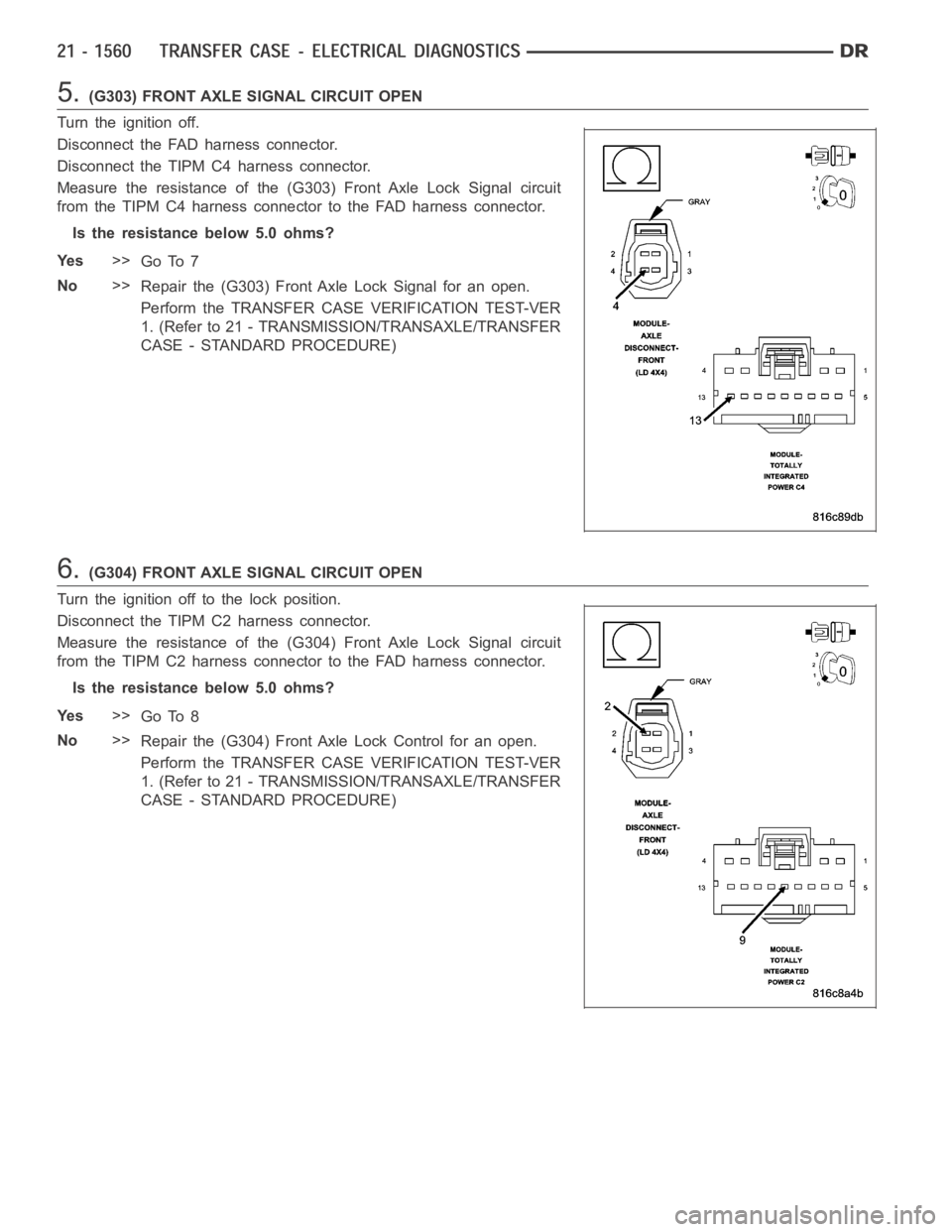
5.(G303) FRONT AXLE SIGNAL CIRCUIT OPEN
Turn the ignition off.
Disconnect the FAD harness connector.
Disconnect the TIPM C4 harness connector.
Measure the resistance of the (G303) Front Axle Lock Signal circuit
from the TIPM C4 harness connector to the FAD harness connector.
Is the resistance below 5.0 ohms?
Ye s>>
Go To 7
No>>
Repair the (G303) Front Axle Lock Signal for an open.
Perform the TRANSFER CASE VERIFICATION TEST-VER
1. (Refer to 21 - TRANSMISSION/TRANSAXLE/TRANSFER
CASE - STANDARD PROCEDURE)
6.(G304) FRONT AXLE SIGNAL CIRCUIT OPEN
Turn the ignition off to the lock position.
Disconnect the TIPM C2 harness connector.
Measure the resistance of the (G304) Front Axle Lock Signal circuit
from the TIPM C2 harness connector to the FAD harness connector.
Is the resistance below 5.0 ohms?
Ye s>>
Go To 8
No>>
Repair the (G304) Front Axle Lock Control for an open.
Perform the TRANSFER CASE VERIFICATION TEST-VER
1. (Refer to 21 - TRANSMISSION/TRANSAXLE/TRANSFER
CASE - STANDARD PROCEDURE)
Page 4087 of 5267
Condition Possible Cause Correction
Lubricant leaking from output shaft
seal or vent.1) Transfer case overfilled. 1) Drain lubricant to the correct
level.
2) Vent closed or restricted. 2) Clear or replace vent as
necessary.
3) Output shaft seals damaged or
installed incorrectly.3) Replace seal as necessary.
Check to ensure that another
component, the propeller shaft slip
yoke for example, is not causing
damage to seal.
Abnormal tire wear. 1) Extended operation on hard, dry
surfaces in the 4H position.1) Operate vehicle in the 2H
position on hard, dry surfaces.
REMOVAL
1. Raise and support vehicle.
2. Remove skid plate, if equipped. (Refer to 13 - FRAMES & BUMPERS/FRAME/TRANSFER CASE SKID PLATE
- REMOVAL)
3. Position drain oil container under transfer case.
4. Remove transfer case drain plug and drain lubricant into container.
5. Disconnect vent hose and transfer case position sensor connector.
6. Disconnect shift rod from grommet in transfer case shift lever, or from floor shift arm whichever provides easy
access. Use channel lock style pliers to press rod out of lever grommet.
7. Support transmission with jack stand.
8. Mark front and rear propeller shafts for assembly reference.
9. Remove front and rear propeller shafts. (Refer to 3 - DIFFERENTIAL & DRIVELINE/PROPELLER SHAFT/PRO-
PELLER SHAFT - REMOVAL)
10. Support transfer case with suitable jack. Secure transfer case to jackwith safety chains.
11. Remove nuts attaching transfer case to transmission.
12. Move transfer case assembly rearward until free of transmission outputshaft.
13. Lower jack and move transfer case from under vehicle.
DISASSEMBLY
Position transfer case in a shallow drain pan. Remove drain plug and drain any remaining lubricant remaining in
case.
SHIFT LEVER AND FRONT OUTPUT SHAFT SEAL
1. Shift transfer case into NEUTRAL.
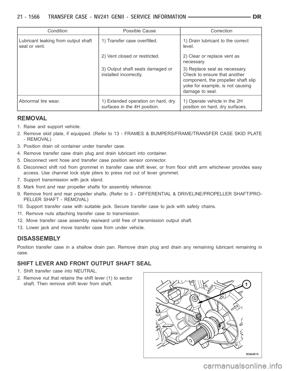
2. Remove nut that retains the shift lever (1) to sector
shaft. Then remove shift lever from shaft.
Page 4100 of 5267
INSPECTION
MAINSHAFT/SPROCKET/HUB
Inspect the splines on the hub and shaft and the teeth on the sprocket. Minornicks and scratches can be smoothed
with an oilstone, however, replace any part that is damaged.
Check the contact surfaces in the sprocket bore and on the mainshaft. Minornicks and scratches can be smoothed
with 320-400 grit emery cloth but do not try to salvage the shaft if nicks or wear is severe.
INPUT GEAR AND PLANETARY CARRIER
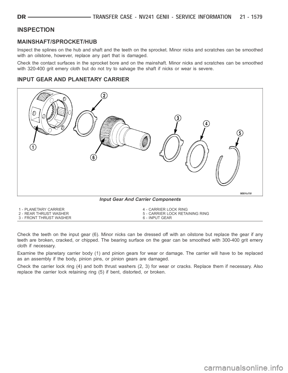
Check the teeth on the input gear (6). Minor nicks can be dressed off with an oilstone but replace the gear if any
teeth are broken, cracked, or chipped. The bearing surface on the gear can besmoothedwith300-400gritemery
cloth if necessary.
Examine the planetary carrier body (1) and pinion gears for wear or damage.The carrier will have to be replaced
as an assembly if the body, pinion pins, or pinion gears are damaged.
Check the carrier lock ring (4) and both thrust washers (2, 3) for wear or cracks. Replace them if necessary. Also
replace the carrier lock retaining ring (5) if bent, distorted, or broken.
Input Gear And Carrier Components
1 - PLANETARY CARRIER 4 - CARRIER LOCK RING
2 - REAR THRUST WASHER 5 - CARRIER LOCK RETAINING RING
3 - FRONT THRUST WASHER 6 - INPUT GEAR
Page 4111 of 5267
17. Install the transfer case position sensor or switch
(2). Tighten the sensor or switch to 20-34 Nꞏm
(16-25 ft. lbs.) torque.
18. Install range lever (1) on sector shaft.
19. Install washer and nut on sector shaft to secure
shift lever. Apply 1-2 drops Mopar
Lock N’ Seal,
or equivalent, to nut threads before installation.
Then tighten nut to 27-34 Nꞏm (20-25 ft. lbs.)
torque.
20. Install new o-ring on detent plug (2).
Page 4115 of 5267
SEAL BOOT
1. Install the front output shaft seal slinger with Oil Slinger Installer 8840. Install the slinger onto the shaft until the
tool contacts the rear of the output shaft.
2. Install a new seal boot clamp onto the seal boot.
3. Install the seal boot and clamp onto the slinger hub and tighten the clampwith Crimp Tool C-4975-A.
REAR EXTENSION
1. Install new seal in rear extension housing seal with
Seal Installer D-163 and universal Handle C-4171..
2. Apply bead of Mopar
Gasket Maker, or equivalent,
to mating surface of rear extension housing. Keep
sealer bead width to maximum of 3/16 inch. Do not
use excessive amount of sealer as excess could
be displaced into output bearing.
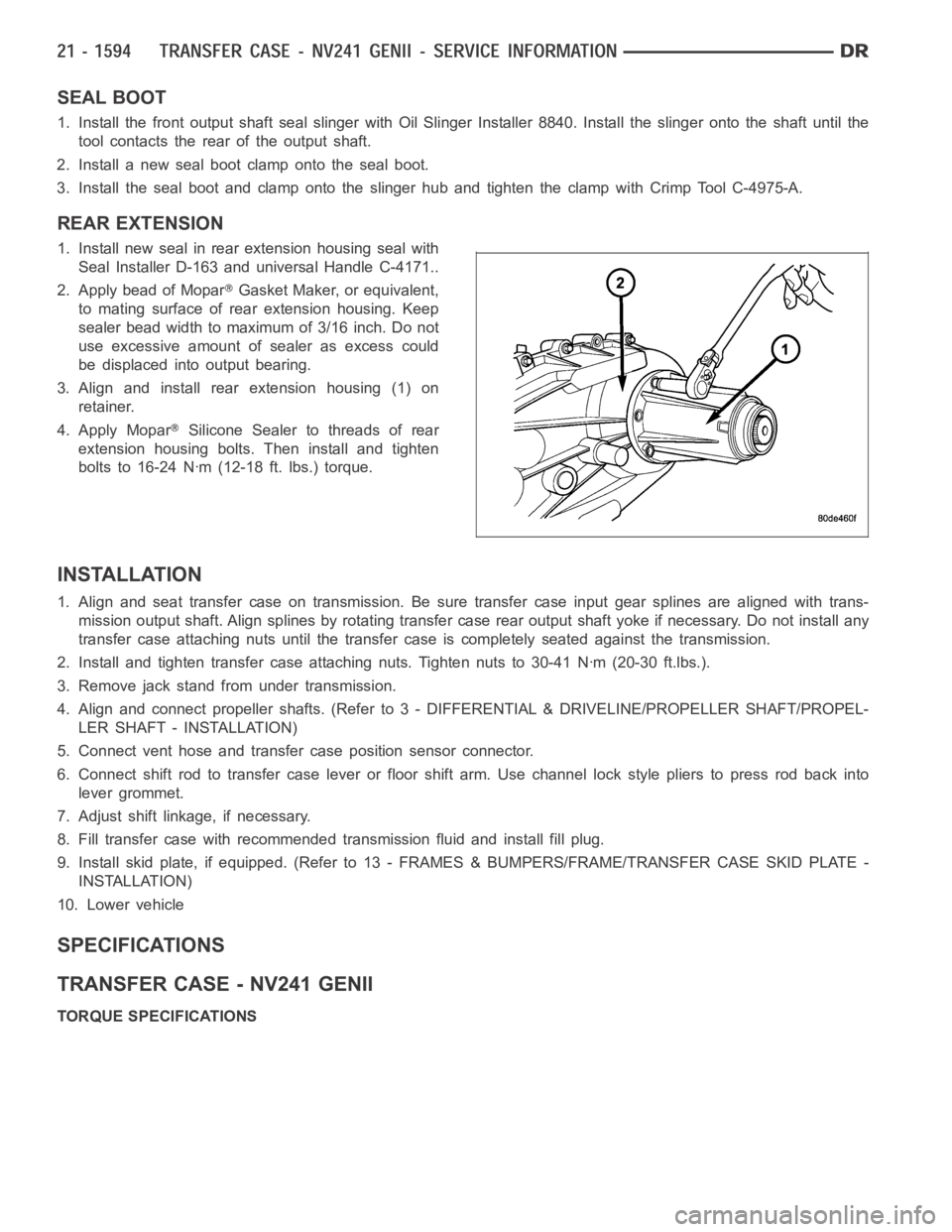
3. Align and install rear extension housing (1) on
retainer.
4. Apply Mopar
Silicone Sealer to threads of rear
extension housing bolts. Then install and tighten
bolts to 16-24 Nꞏm (12-18 ft. lbs.) torque.
INSTALLATION
1. Align and seat transfer case on transmission. Be sure transfer case input gear splines are aligned with trans-
mission output shaft. Align splines by rotating transfer case rear outputshaft yoke if necessary. Do not install any
transfer case attaching nuts until the transfer case is completely seatedagainst the transmission.
2. Install and tighten transfer case attaching nuts. Tighten nuts to 30-41Nꞏm (20-30 ft.lbs.).
3. Remove jack stand from under transmission.
4. Align and connect propeller shafts. (Refer to 3 - DIFFERENTIAL & DRIVELINE/PROPELLER SHAFT/PROPEL-
LER SHAFT - INSTALLATION)
5. Connect vent hose and transfer case position sensor connector.
6. Connect shift rod to transfer case lever or floor shift arm. Use channel lock style pliers to press rod back into
lever grommet.
7. Adjust shift linkage, if necessary.
8. Fill transfer case with recommended transmission fluid and install fillplug.
9. Install skid plate, if equipped. (Refer to 13 - FRAMES & BUMPERS/FRAME/TRANSFER CASE SKID PLATE -
INSTALLATION)
10. Lower vehicle
SPECIFICATIONS
TRANSFER CASE - NV241 GENII
TORQUE SPECIFICATIONS
Page 4123 of 5267
LEVER-SHIFT
REMOVAL
1. Shift transfer case into 2H.
2. Raise and support the vehicle.
3. Loosen adjusting trunnion lock bolt and slide shift rod out of trunnion.If rod lacks enough travel to come out of
trunnion, push trunnion out of shift lever.
4. Lower vehicle.
5. Remove transfer case shifter knob cap.
6. Remove nut holding shifter knob (2) to shift lever.
7. Remove shifter knob.
8. Remove the shift boot from the shifter console.
9. Remove the bolts securing the shifter mechanism to the floor pan.
10. Separate shift lever mechanism from the vehicle.
Transfer Case Shifter
1 - SHIFTER BOOT 4 - SHIFTER MECHANISM
2-SHIFTERKNOB 5-ALIGNMENTPIN
3 - SHIFTER CONSOLE 6 - TRANSFER CASE
Page 4124 of 5267
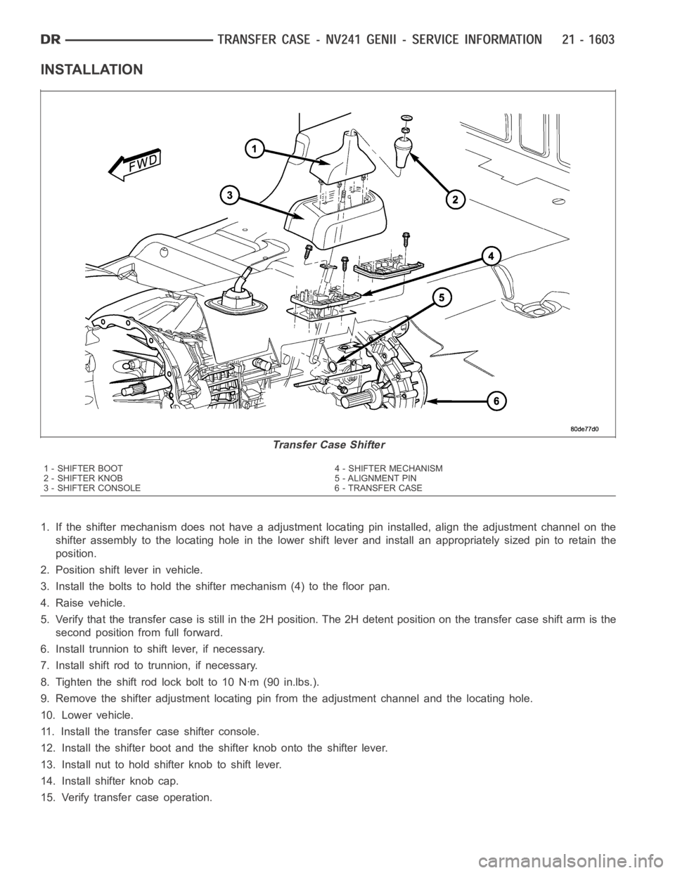
INSTALLATION
1. If the shifter mechanism does not have a adjustment locating pin installed, align the adjustment channel on the
shifter assembly to the locating hole in the lower shift lever and install an appropriately sized pin to retain the
position.
2. Position shift lever in vehicle.
3. Install the bolts to hold the shifter mechanism (4) to the floor pan.
4. Raise vehicle.
5. Verify that the transfer case is still in the 2H position. The 2H detent position on the transfer case shift arm is the
second position from full forward.
6. Install trunnion to shift lever, if necessary.
7. Install shift rod to trunnion, if necessary.
8. Tighten the shift rod lock bolt to 10 Nꞏm (90 in.lbs.).
9. Remove the shifter adjustment locating pin from the adjustment channeland the locating hole.
10. Lower vehicle.
11. Install the transfer case shifter console.
12. Install the shifter boot and the shifter knob onto the shifter lever.
13. Install nut to hold shifter knob to shift lever.
14. Install shifter knob cap.
15. Verify transfer case operation.
Transfer Case Shifter
1 - SHIFTER BOOT 4 - SHIFTER MECHANISM
2-SHIFTERKNOB 5-ALIGNMENTPIN
3 - SHIFTER CONSOLE 6 - TRANSFER CASE