2006 DODGE RAM SRT-10 lock
[x] Cancel search: lockPage 4693 of 5267
INSTALLATION
WARNING: Always keep hands and clothing clear
of the wire rope, hook and fairlead opening during
operation and when spooling. Failure to follow
these instructions may result in personal injury or
death.
CAUTION: Wire rope must spool on the winch
drum in the direction indicated.
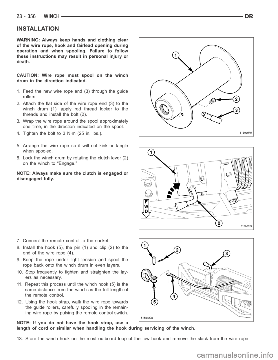
1. Feed the new wire rope end (3) through the guide
rollers.
2. Attach the flat side of the wire rope end (3) to the
winch drum (1), apply red thread locker to the
threads and install the bolt (2).
3. Wrap the wire rope around the spool approximately
one time, in the direction indicated on the spool.
4. Tighten the bolt to 3 Nꞏm (25 in. lbs.).
5. Arrange the wire rope so it will not kink or tangle
when spooled.
6. Lock the winch drum by rotating the clutch lever (2)
on the winch to “Engage.”
NOTE: Always make sure the clutch is engaged or
disengaged fully.
7. Connect the remote control to the socket.
8. Install the hook (5), the pin (1) and clip (2) to the
end of the wire rope (4).
9. Keep the rope under light tension and spool the
rope back onto the winch drum in even layers.
10. Stop frequently to tighten and straighten the lay-
ers as necessary.
11. Repeat this process until the winch hook (5) is the
same distance from the winch as the full length of
theremotecontrol.
12. Using the hook strap, walk the wire rope towards
the guide rollers, carefully spooling in the remain-
ing wire rope by pulsing the remote control switch.
NOTE: If you do not have the hook strap, use a
length of cord or similar when handling the hook during servicing of the winch.
13. Store the winch hook on the most outboard loop of the tow hook and remove the slack from the wire rope.
Page 4887 of 5267
When Monitored:
With the ignition on.
Set Condition:
The Totally Integrated Power Module (TIPM) will set this DTC if it detects an overcurrent condition on the
(F942) Fused Ignition Switch Output (Run-Start) circuit for more than 500ms when blower motor operation is
requested.
Possible Causes
TERMINAL DAMAGE OR CORROSION
HIGH RESISTANCE ON (F942) FUSED IGNITION SWITCH OUTPUT (RUN-START) CIRCUIT
HIGH RESISTANCE ON (C70) BLOWER MOTOR HIGH DRIVER CIRCUIT
HIGH RESISTANCE ON (Z134) GROUND CIRCUIT
BLOCKAGE STALLING BLOWER MOTOR
BLOWER MOTOR
TIPM
A/C HEATER CONTROL
Diagnostic Test
1.CHECK FOR AN ACTIVE OR STORED DTC B10E9 BLOWER MOTOR CONTROL CIRCUIT LOW IN THE
TIPM
Turn the ignition on.
With the scan tool, read TIPM DTCs.
Does the scan tool display active or stored DTC B10E9 BLOWER MOTOR CONTROL CIRCUIT LOW?
Ye s>>
Diagnose and repair the DTC. Refer to the Table of Contents in this section for a complete list of HVAC
related symptoms.
No>>
Go To 2
2.INSPECT THE TIPM & BLOWER MOTOR CONNECTOR TERMINALS & WIRE HARNESS FOR A
CONDITION CAUSING HIGH CIRCUIT RESISTANCE
Turn the ignition off.
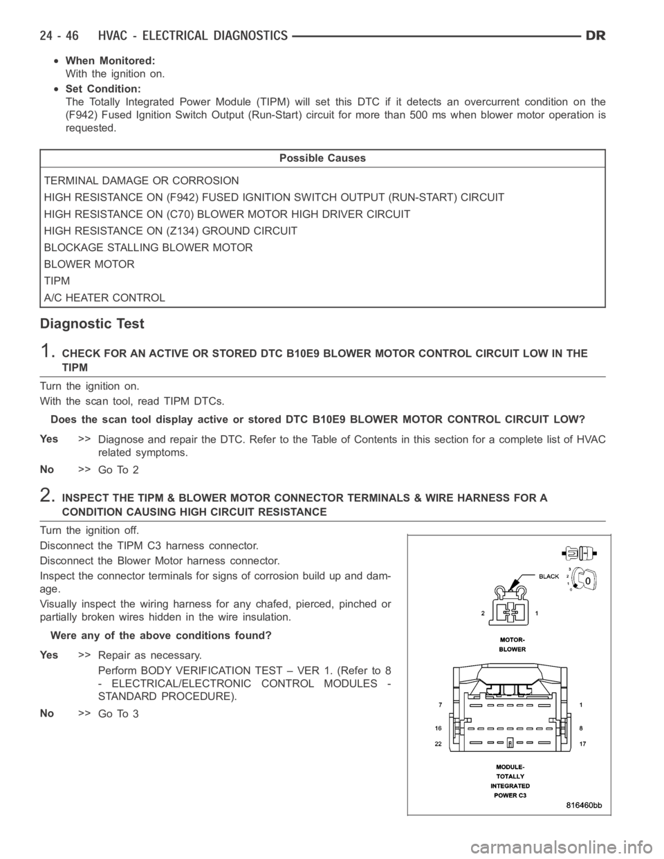
Disconnect the TIPM C3 harness connector.
Disconnect the Blower Motor harness connector.
Inspect the connector terminals for signs of corrosion build up and dam-
age.
Visually inspect the wiring harness for any chafed, pierced, pinched or
partially broken wires hidden in the wire insulation.
Were any of the above conditions found?
Ye s>>
Repair as necessary.
Perform BODY VERIFICATION TEST – VER 1. (Refer to 8
- ELECTRICAL/ELECTRONIC CONTROL MODULES -
STANDARD PROCEDURE).
No>>
Go To 3
Page 4889 of 5267
5.CHECK THE OUTPUT FROM THE TIPM ON THE (F942) FUSED IGNITION SWITCH OUTPUT (RUN-START)
CIRCUIT
Reconnect the TIPM C3 harness connector.
Turn the ignition on.
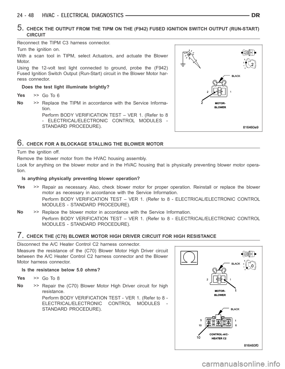
With a scan tool in TIPM, select Actuators, and actuate the Blower
Motor.
Using the 12-volt test light connected to ground, probe the (F942)
Fused Ignition Switch Output (Run-Start) circuit in the Blower Motor har-
ness connector.
Does the test light illuminate brightly?
Ye s>>
Go To 6
No>>
Replace the TIPM in accordance with the Service Informa-
tion.
Perform BODY VERIFICATION TEST – VER 1. (Refer to 8
- ELECTRICAL/ELECTRONIC CONTROL MODULES -
STANDARD PROCEDURE).
6.CHECK FOR A BLOCKAGE STALLING THE BLOWER MOTOR
Turn the ignition off.
Remove the blower motor from the HVAC housing assembly.
Look for anything on the blower motor and in the HVAC housing that is physically preventing blower motor opera-
tion.
Is anything physically preventing blower operation?
Ye s>>
Repair as necessary. Also, check blower motor for proper operation. Reinstall or replace the blower
motor as necessary in accordancewith the Service Information.
Perform BODY VERIFICATION TEST – VER 1. (Refer to 8 - ELECTRICAL/ELECTRONIC CONTROL
MODULES - STANDARD PROCEDURE).
No>>
Replace the blower motor in accordance with the Service Information.
Perform BODY VERIFICATION TEST – VER 1. (Refer to 8 - ELECTRICAL/ELECTRONIC CONTROL
MODULES - STANDARD PROCEDURE).
7.CHECK THE (C70) BLOWER MOTOR HIGH DRIVER CIRCUIT FOR HIGH RESISTANCE
Disconnect the A/C Heater Control C2 harness connector.
Measure the resistance of the (C70) Blower Motor High Driver circuit
between the A/C Heater Control C2 harness connector and the Blower
Motor harness connector.
Is the resistance below 5.0 ohms?
Ye s>>
Go To 8
No>>
Repair the (C70) Blower Motor High Driver circuit for high
resistance.
Perform BODY VERIFICATION TEST - VER 1. (Refer to 8 -
ELECTRICAL/ELECTRONIC CONTROL MODULES -
STANDARD PROCEDURE).
Page 5055 of 5267
Condition Possible Causes Correction
2. Faulty fuse.2. Check the fuse in the junction block. Repair the
shorted circuit or component and replace the fuse,
if required.
3. Faulty A/C compressor
clutch field coil.3. See A/C Compressor Clutch Field Coil in this
group. Test the compressor clutch field coil and
replace, if required.
4. Improperly installed or
faulty Evaporator
Temperature Sensor.4. See Evaporator Temperature Sensor in this
group. Correctly install or replace the sensor as
required.
5. Faulty A/C pressure
transducer.5. See A/C pressure transducer in this group. Test
the transducer and replace, if required.
6. Faulty A/C-heater control,
totally integrated power
module (TIPM), gateway
module or PCM/ECM.6. Refer to the appropriate Electrical Diagnostic
Procedures for testing of the A/C-heater control,
TIPM, gateway module or PCM/ECM. Test the
module and replace, if required.
Normal pressures, but A/C
Performance Test air
temperatures at center panel
outlet are too high.1. Excessive refrigerant oil in
system.1. See Refrigerant Oil Level in this group. Recover
the refrigerant from the refrigerant system and
inspect the refrigerant oil content. Restore the
refrigerant oil to the proper level, if required.
2. Blend door inoperative or
sealing improperly.2. See Blend Door in this group. Inspect the blend
door for proper operation and sealing and correct,
if required.
3. Blend door actuator faulty
or inoperative.3. Perform blend door actuator diagnosis, replace
if faulty.
The low side pressure is
normal or slightly low, and
the high side pressure is too
low.1. Low refrigerant system
charge.1. See Refrigerant System Leaks in this group.
Test the refrigerant system for leaks. Repair,
evacuate and charge the refrigerant system, if
required.
2. Refrigerant flow through
the accumulator is restricted.2. See Accumulator in this group. Replace the
restricted accumulator, if required.
3. Refrigerant flow through
the evaporator coil is
restricted.3. See A/C Evaporator in this group. Replace the
restricted evaporator coil, if required.
4. Faulty compressor.4. See A/C Compressor in this group. Replace the
compressor, if required.
The low side pressure is
normal or slightly high, and
the high side pressure is too
high.1. Condenser air flow
restricted.1. Check the A/C condenser for damaged fins,
foreign objects obstructing air flow through the
condenser fins, and missing or improperly
installed air seals. Refer to Cooling for more
information on air seals. Clean, repair, or replace
components as required.
2. Inoperative cooling fan.2. Refer to Cooling for more information. Test the
cooling fan and replace, if required.
3. Refrigerant system
overcharged.3. See Refrigerant System Charge in this group.
Recover the refrigerant from the refrigerant
system. Charge the refrigerant system to the
proper level, if required.
4. Air in the refrigerant
system.4. See Refrigerant System Leaks in this group.
Test the refrigerant system for leaks. Repair,
evacuate and charge the refrigerant system, if
required.
Page 5077 of 5267
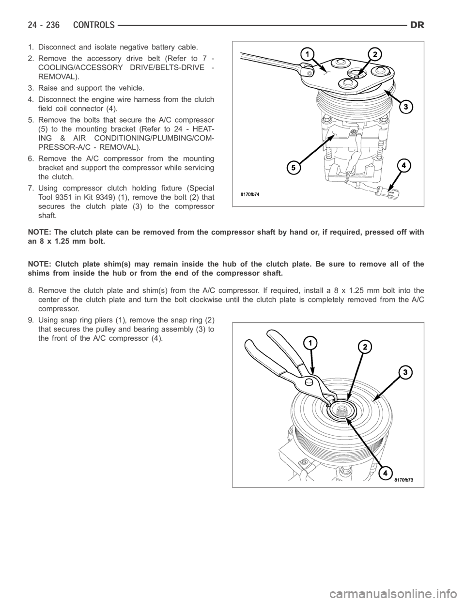
1. Disconnect and isolate negative battery cable.
2. Remove the accessory drive belt (Refer to 7 -
COOLING/ACCESSORY DRIVE/BELTS-DRIVE -
REMOVAL).
3. Raise and support the vehicle.
4. Disconnect the engine wire harness from the clutch
field coil connector (4).
5. Remove the bolts that secure the A/C compressor
(5)tothemountingbracket(Referto24-HEAT-
ING & AIR CONDITIONING/PLUMBING/COM-
PRESSOR-A/C - REMOVAL).
6. Remove the A/C compressor from the mounting
bracket and support the compressor while servicing
the clutch.
7. Using compressor clutch holding fixture (Special
Tool 9351 in Kit 9349) (1), remove the bolt (2) that
secures the clutch plate (3) to the compressor
shaft.
NOTE: The clutch plate can be removed from the compressor shaft by hand or, if required, pressed off with
an 8 x 1.25 mm bolt.
NOTE: Clutch plate shim(s) may remain inside the hub of the clutch plate. Besure to remove all of the
shims from inside the hub or from the end of the compressor shaft.
8. Remove the clutch plate and shim(s) from the A/C compressor. If required, install a 8 x 1.25 mm bolt into the
centeroftheclutchplateandturntheboltclockwiseuntiltheclutchplate is completely removed from the A/C
compressor.
9. Using snap ring pliers (1), remove the snap ring (2)
that secures the pulley and bearing assembly (3) to
the front of the A/C compressor (4).
Page 5078 of 5267
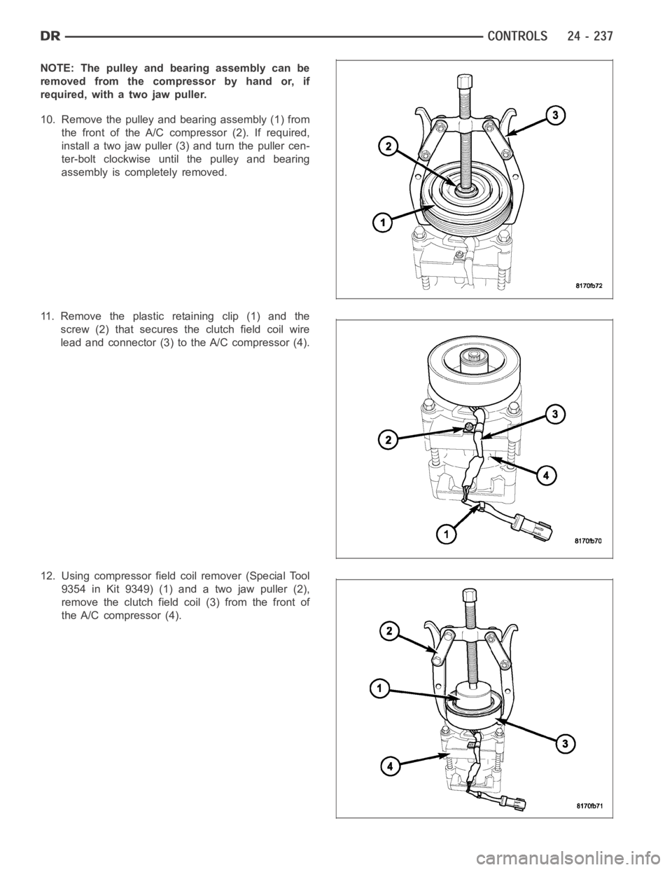
NOTE: The pulley and bearing assembly can be
removed from the compressor by hand or, if
required, with a two jaw puller.
10. Remove the pulley and bearing assembly (1) from
the front of the A/C compressor (2). If required,
install a two jaw puller (3) and turn the puller cen-
ter-bolt clockwise until the pulley and bearing
assembly is completely removed.
11. Remove the plastic retaining clip (1) and the
screw (2) that secures the clutch field coil wire
lead and connector (3) to the A/C compressor (4).
12. Using compressor field coil remover (Special Tool
9354 in Kit 9349) (1) and a two jaw puller (2),
remove the clutch field coil (3) from the front of
the A/C compressor (4).
Page 5079 of 5267
INSTALLATION
DENSO A/C COMPRESSOR
NOTE: Typical A/C compressor shown in illustrations.
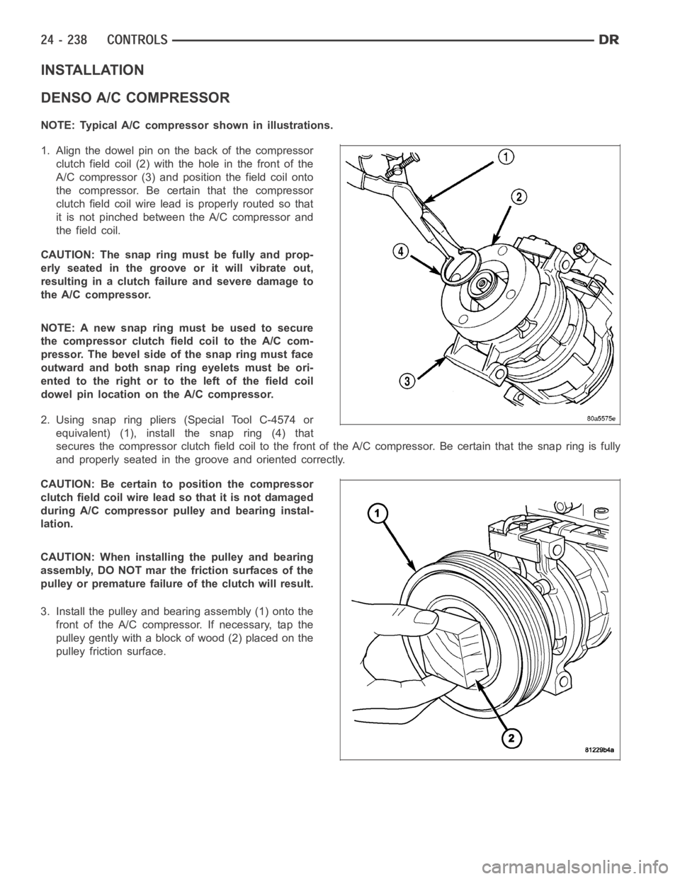
1. Align the dowel pin on the back of the compressor
clutch field coil (2) with the hole in the front of the
A/C compressor (3) and position the field coil onto
the compressor. Be certain that the compressor
clutch field coil wire lead is properly routed so that
it is not pinched between the A/C compressor and
the field coil.
CAUTION:Thesnapringmustbefullyandprop-
erly seated in the groove or it will vibrate out,
resulting in a clutch failure and severe damage to
the A/C compressor.
NOTE:Anewsnapringmustbeusedtosecure
the compressor clutch field coil to the A/C com-
pressor. The bevel side of the snap ring must face
outward and both snap ring eyelets must be ori-
ented to the right or to the left of the field coil
dowel pin location on the A/C compressor.
2. Using snap ring pliers (Special Tool C-4574 or
equivalent) (1), install the snap ring (4) that
secures the compressor clutch field coil to the front of the A/C compressor. Be certain that the snap ring is fully
and properly seated in the groove and oriented correctly.
CAUTION:Becertaintopositionthecompressor
clutch field coil wire lead so that it is not damaged
during A/C compressor pulley and bearing instal-
lation.
CAUTION: When installing the pulley and bearing
assembly, DO NOT mar the friction surfaces of the
pulley or premature failure of the clutch will result.
3. Install the pulley and bearing assembly (1) onto the
front of the A/C compressor. If necessary, tap the
pulley gently with a block of wood (2) placed on the
pulley friction surface.
Page 5121 of 5267
MOTOR-BLOWER
DESCRIPTION
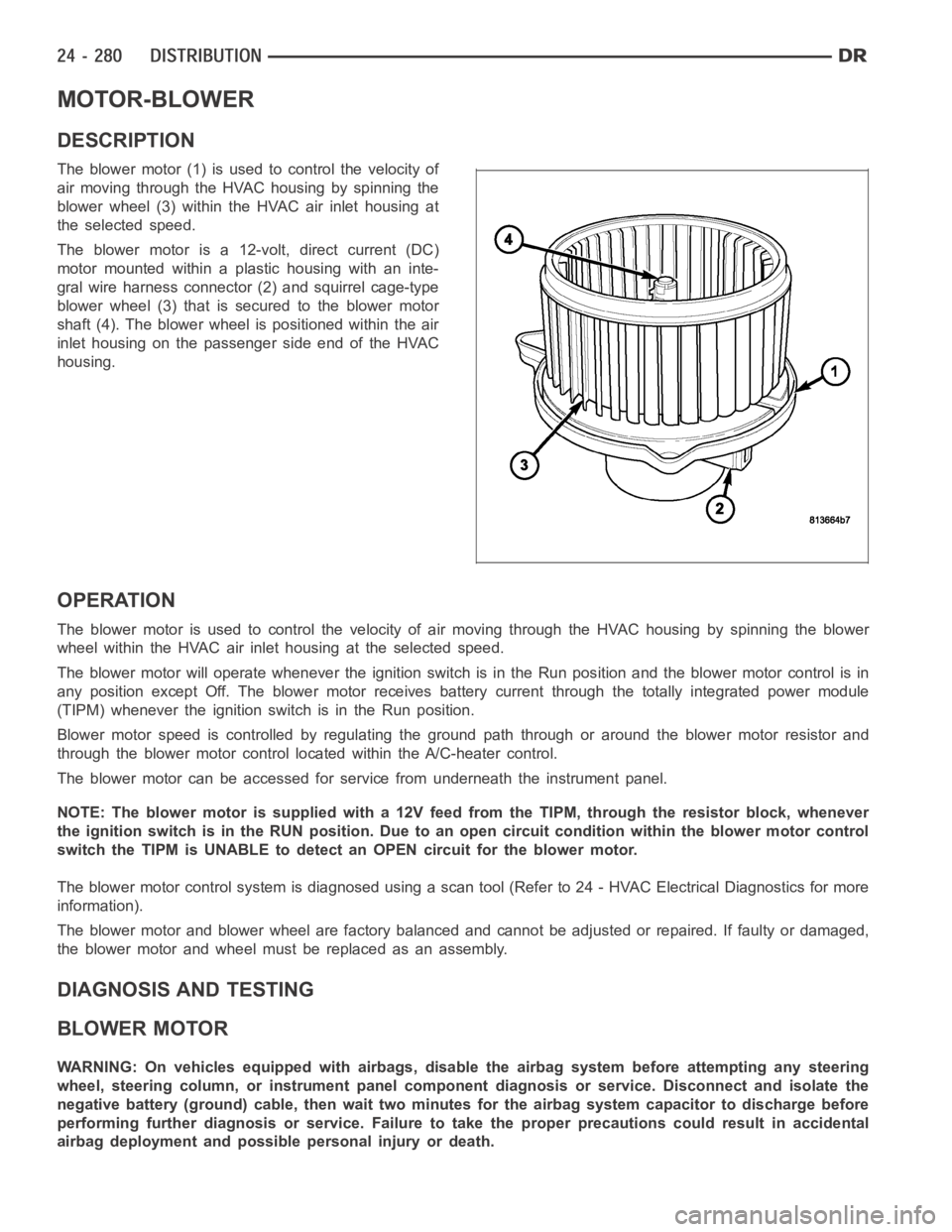
The blower motor (1) is used to control the velocity of
air moving through the HVAC housing by spinning the
blower wheel (3) within the HVAC air inlet housing at
the selected speed.
The blower motor is a 12-volt, direct current (DC)
motormountedwithinaplastichousingwithaninte-
gral wire harness connector (2) and squirrel cage-type
blower wheel (3) that is secured to the blower motor
shaft (4). The blower wheel is positioned within the air
inlet housing on the passenger side end of the HVAC
housing.
OPERATION
The blower motor is used to control the velocity of air moving through the HVAC housing by spinning the blower
wheel within the HVAC air inlet housing at the selected speed.
The blower motor will operate whenever the ignition switch is in the Run position and the blower motor control is in
any position except Off. The blower motor receives battery current through the totally integrated power module
(TIPM) whenever the ignition switch is in the Run position.
Blower motor speed is controlled by regulating the ground path through or around the blower motor resistor and
through the blower motor control located within the A/C-heater control.
The blower motor can be accessed for service from underneath the instrument panel.
NOTE: The blower motor is supplied with a 12V feed from the TIPM, through theresistor block, whenever
the ignition switch is in the RUN position. Due to an open circuit conditionwithin the blower motor control
switch the TIPM is UNABLE to detect an OPEN circuit for the blower motor.
The blower motor control system is diagnosed using a scan tool (Refer to 24 -HVAC Electrical Diagnostics for more
information).
The blower motor and blower wheel are factory balanced and cannot be adjusted or repaired. If faulty or damaged,
the blower motor and wheel must be replaced as an assembly.
DIAGNOSIS AND TESTING
BLOWER MOTOR
WARNING: On vehicles equipped with airbags, disable the airbag system before attempting any steering
wheel, steering column, or instrument panel component diagnosis or service. Disconnect and isolate the
negative battery (ground) cable, then wait two minutes for the airbag system capacitor to discharge before
performing further diagnosis or service. Failure to take the proper precautions could result in accidental
airbag deployment and possible personal injury or death.