2006 DODGE RAM SRT-10 lock
[x] Cancel search: lockPage 5122 of 5267
NOTE: The blower motor is supplied with a 12V feed from the TIPM, through theresistor block, whenever
the ignition switch is in the RUN position. Due to an open circuit conditionwithin the blower motor control
switch the TIPM is UNABLE to detect an OPEN circuit for the blower motor.
To determine if an open condition exists within the blower motor circuit wiring, it is necessary to disconnect the
negative battery cable and check for continuity within the blower motor circuits using an ohmmeter. For circuit
descriptions and diagrams, refer to Air Conditioning/Heater in Group 8W -Wiring Diagrams.
OPERATION
Possible causes of the blower motor not operating include:
Faulty blower motor
Faulty blower motor circuit wiring or wire harness connectors
Faulty blower motor control
Possible causes of the blower motor not operating in one or more speeds include:
Faulty blower motor resistor
Faulty blower motor circuit wiring or wire harness connectors
Faulty blower motor control
VIBRATION
Possible causes of blower motor vibration include:
Improper blower motor mounting
Improper blower wheel mounting
Deformed blower wheel
Out of balance blower wheel due to foreign material in the wheel
Faulty blower motor
NOISE
To determine if the blower motor is the source of the noise, simply switch the blower motor from Off to On. To verify
that the blower motor is the source of the noise, unplug the blower motor wire harness connector and operate the
heating-A/C system. If the noise goes away, possible causes include:
Foreign material in the HVAC air inlet housing
Improper blower motor mounting
Improper blower wheel mounting
Faulty blower motor
Page 5127 of 5267
PLUMBING
DESCRIPTION
The A/C refrigerant lines and hoses are used to carry the refrigerant between the various A/C system components.
The refrigerant lines and hoses for the R-134a system on this vehicle consist of a barrier-hose design with a nylon
tube sandwiched between rubber layers. The nylon tube helps to contain theR-134a refrigerant, which has a
smaller molecular structure than R-12 refrigerant. The ends of the refrigerant lines are made from lightweight alu-
minum or steel, and commonly use braze-less fittings.
Any kinks or sharp bends in the refrigerant lines and hoses will reduce the capacity of the entire A/C system and
can reduce the flow of refrigerant in the system. The radius of all bends in the flexible hose refrigerant lines should
be at least ten times the diameter of the hose and the refrigerant lines should be routed so they are at least 80
millimeters (3 inches) away from the exhaust manifold(s) and exhaust pipe(s).
OPERATION
High pressures are produced in the refrigerant system when the A/C compressor is operating. Extreme care must
be exercised to make sure that each of the refrigerant system connections is pressure-tight and leak free. It is a
good practice to inspect all flexible hose refrigerant lines at least oncea year to make sure they are in good con-
dition and properly routed.
The refrigerant lines and hoses are coupled to other A/C system componentswith block-type fittings. An O-ring seal,
or a flat steel gasket with an integral O-ring (dual plane seal), is used to mate the refrigerant line fittings with A/C
system components to ensure the integrity of the refrigerant system.
The refrigerant lines and hoses cannot be repaired and, if faulty or damaged, they must be replaced.
WARNING
WARNING: The A/C system contains refrigerant under high pressure. Repairs should only be performed by
qualified service personnel. Severe personal injury or death may result from improper service procedures.
WARNING: Avoid breathing the refrigerant and refrigerant oil vapor or mist. Exposure may irritate the eyes,
nose, and/or throat. Wear eye protection when servicing the A/C refrigerant system. Serious eye injury can
result from direct contact with the refrigerant. If eye contact occurs, seek medical attention immediately.
WARNING: Do not expose the refrigerant to open flame. Poisonous gas is createdwhenrefrigerantis
burned. An electronic leak detector is recommended. Severe personal injury or death may result from
improper service procedures.
WARNING: If accidental system discharge occurs, ventilate the work area before resuming service. Large
amounts of refrigerant released in a closed work area will displace the oxygen and cause suffocation and
death.
WARNING: The evaporation rate of R-134a refrigerant at average temperature and altitude is extremely high.
As a result, anything that comes in contact with the refrigerant will freeze. Always protect the skin or del-
icate objects from direct contact with the refrigerant.
WARNING: The R-134a service equipment or the vehicle refrigerant system should not be pressure tested or
leak tested with compressed air. Some mixtures of air and R-134a have been shown to be combustible at
elevated pressures. These mixtures are potentially dangerous, and may result in fire or explosion causing
property damage, personal injury or death.
Page 5128 of 5267
WARNING: The engine cooling system is designed to develop internal pressures up to 145 kilopascals (21
pounds per square inch). Do not remove or loosen the coolant pressure cap, cylinder block drain plugs,
radiator drain, radiator hoses, heater hoses, or hose clamps while the engine cooling system is hot and
under pressure. Allow the vehicle to cool for a minimum of 15 minutes beforeopening the cooling system
for service. Failure to observe this warning can result in serious burns from the heated engine coolant.
CAUTION
CAUTION: Never add R-12 to a refrigerant system designed to use R-134a. Do not use R-12 equipment or
parts on an R-134a A/C system. These refrigerants are not compatible and damage to the A/C system will
result.
CAUTION: Never use R-12 refrigerant oil in a A/C system designed to use R-134a refrigerant oil. These
refrigerant oils are not compatible and damage to the A/C system will result.
CAUTION: The use of A/C system sealers may result in damage to A/C refrigerant recovery/evacuation/re-
charging equipment and/or A/C system. Many federal, state/provincial and local regulations prohibit the
recharge of A/C systems with known leaks. DaimlerChrysler recommends thedetection of A/C system leaks
through the use of approved leak detectors and fluorescent leak detectiondyes. Vehicles found with A/C
system sealers should be treated as contaminated and replacement of the entire A/C refrigerant system is
recommended. A/C systems found to be contaminated with A/C system sealers, A/C stop-leak products or
seal conditioners voids the warranty for the A/C system.
CAUTION: Recover the refrigerant before opening any fitting or connection. Open the fittings with caution,
even after the system has been discharged. Never open or loosen a connection before recovering the refrig-
erant.
CAUTION: If equipped, do not remove the secondary retention clip from any spring-lock coupler connection
while the refrigerant system is under pressure. Recover the refrigerant before removing the secondary
retention clip. Open the fittings with caution, even after the system has been discharged. Never open or
loosen a connection before recovering the refrigerant.
CAUTION: The internal parts of the A/C system will remain stable as long as moisture-free refrigerant and
refrigerant oil is used. Abnormal amounts of dirt, moisture or air can upset the chemical stability. This may
cause operational troubles or even serious damage if present in more than very small quantities. Before
disconnecting a component, clean the outside of the fittings thoroughly to prevent contamination from
entering the refrigerant system. Keep service tools and the work area clean. Do not open the refrigerant
system or uncap a replacement component until you are ready to service the system. Immediately after
disconnecting a component from the refrigerant system, seal the open fittings with a cap or plug. This will
prevent contamination from entering the A/C system.
CAUTION: Refrigerant oil will absorb moisture from the atmosphere if leftuncapped. Do not open a con-
tainer of refrigerant oil until you are ready to use it. Replace the cap on the oil container immediately after
using. Store refrigerant oil only in a clean, airtight, and moisture-freecontainer.
CAUTION: Do not overcharge the refrigerant system. Overcharging will cause excessive compressor head
pressure and can cause compressor noise and A/C system failure.
Page 5130 of 5267
STANDARD PROCEDURE
REFRIGERANT SYSTEM SERVICE EQUIPMENT
WARNING: Eye protection must be worn when servicing an A/C refrigerant system. Turn all valves off
(rotate clockwise) on the equipment being used before connecting or disconnecting service equipment from
the refrigerant system. Failure to observe these warnings may result in personal injury or death.
WARNING: Refer to the applicable warnings and cautions for this system before performing the following
operation (Refer to 24 - HEATING & AIR CONDITIONING/PLUMBING - WARNINGS) and (Refer to 24 - HEAT-
ING & AIR CONDITIONING/PLUMBING - CAUTIONS). Failure to follow the warnings and cautions could result
in possible personal injury or death.
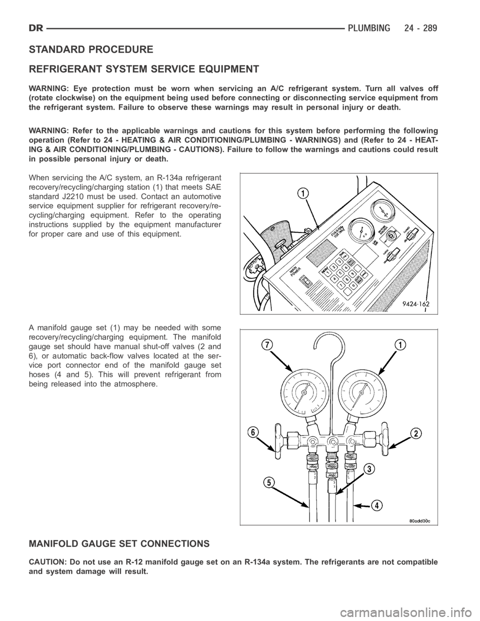
When servicing the A/C system, an R-134a refrigerant
recovery/recycling/charging station (1) that meets SAE
standard J2210 must be used. Contact an automotive
service equipment supplier for refrigerant recovery/re-
cycling/charging equipment. Refer to the operating
instructions supplied by the equipment manufacturer
for proper care and use of this equipment.
A manifold gauge set (1) may be needed with some
recovery/recycling/charging equipment. The manifold
gauge set should have manual shut-off valves (2 and
6), or automatic back-flow valves located at the ser-
vice port connector end of the manifold gauge set
hoses (4 and 5). This will prevent refrigerant from
being released into the atmosphere.
MANIFOLD GAUGE SET CONNECTIONS
CAUTION: Do not use an R-12 manifold gauge set on an R-134a system. The refrigerants are not compatible
and system damage will result.
Page 5134 of 5267
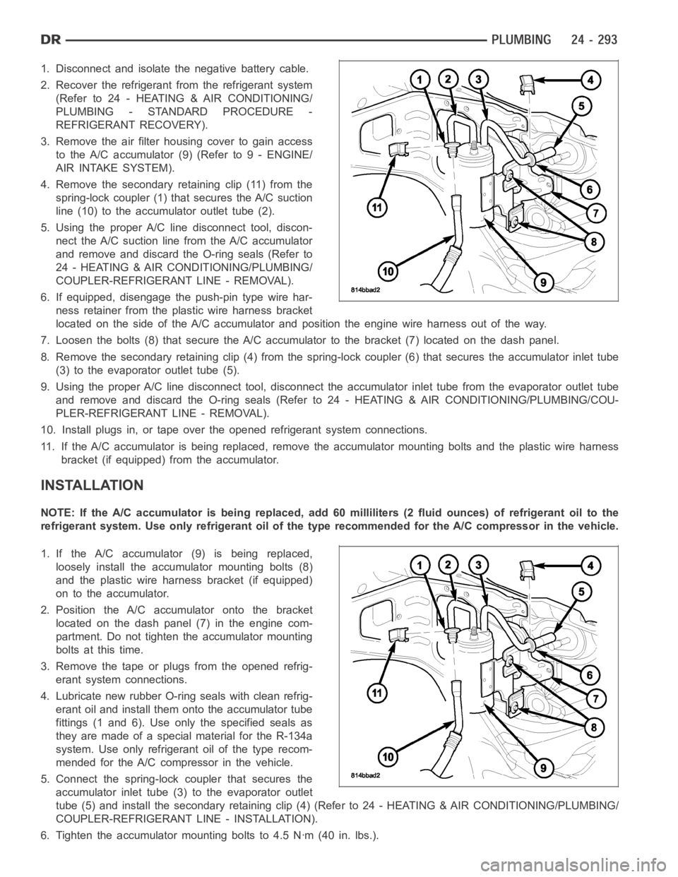
1. Disconnect and isolate the negative battery cable.
2. Recover the refrigerant from the refrigerant system
(Refer to 24 - HEATING & AIR CONDITIONING/
PLUMBING - STANDARD PROCEDURE -
REFRIGERANT RECOVERY).
3. Remove the air filter housing cover to gain access
to the A/C accumulator (9) (Refer to 9 - ENGINE/
AIR INTAKE SYSTEM).
4. Remove the secondary retaining clip (11) from the
spring-lock coupler (1) that secures the A/C suction
line (10) to the accumulator outlet tube (2).
5. Using the proper A/C line disconnect tool, discon-
nect the A/C suction line from the A/C accumulator
and remove and discard the O-ring seals (Refer to
24 - HEATING & AIR CONDITIONING/PLUMBING/
COUPLER-REFRIGERANT LINE - REMOVAL).
6. If equipped, disengage the push-pin type wire har-
ness retainer from the plastic wire harness bracket
located on the side of the A/C accumulator and position the engine wire harness out of the way.
7. Loosen the bolts (8) that secure the A/C accumulator to the bracket (7) located on the dash panel.
8. Remove the secondary retaining clip (4) from the spring-lock coupler (6) that secures the accumulator inlet tube
(3) to the evaporator outlet tube (5).
9. Using the proper A/C line disconnect tool, disconnect the accumulator inlet tube from the evaporator outlet tube
and remove and discard the O-ring seals (Refer to 24 - HEATING & AIR CONDITIONING/PLUMBING/COU-
PLER-REFRIGERANT LINE - REMOVAL).
10. Install plugs in, or tape over the opened refrigerant system connections.
11. If the A/C accumulator is being replaced, remove the accumulator mounting bolts and the plastic wire harness
bracket (if equipped) from the accumulator.
INSTALLATION
NOTE: If the A/C accumulator is being replaced, add 60 milliliters (2 fluidounces) of refrigerant oil to the
refrigerant system. Use only refrigerant oil of the type recommended for the A/C compressor in the vehicle.
1. If the A/C accumulator (9) is being replaced,
loosely install the accumulator mounting bolts (8)
and the plastic wire harness bracket (if equipped)
on to the accumulator.
2. Position the A/C accumulator onto the bracket
located on the dash panel (7) in the engine com-
partment. Do not tighten the accumulator mounting
bolts at this time.
3. Remove the tape or plugs from the opened refrig-
erant system connections.
4. Lubricate new rubber O-ring seals with clean refrig-
erant oil and install them onto the accumulator tube
fittings (1 and 6). Use only the specified seals as
they are made of a special material for the R-134a
system. Use only refrigerant oil of the type recom-
mended for the A/C compressor in the vehicle.
5. Connect the spring-lock coupler that secures the
accumulator inlet tube (3) to the evaporator outlet
tube (5) and install the secondary retaining clip (4) (Refer to 24 - HEATING& AIR CONDITIONING/PLUMBING/
COUPLER-REFRIGERANT LINE - INSTALLATION).
6. Tighten the accumulator mounting bolts to 4.5 Nꞏm (40 in. lbs.).
Page 5140 of 5267
1. Recover the refrigerant from the refrigerant system
(Refer to 24 - HEATING & AIR CONDITIONING/
PLUMBING - STANDARD PROCEDURE -
REFRIGERANT SYSTEM RECOVERY).
2. Disconnect and isolate the negative battery cable.
3. Remove the accessory drive belt (Refer to 7 -
COOLING/ACCESSORY DRIVE/BELTS-DRIVE -
REMOVAL).
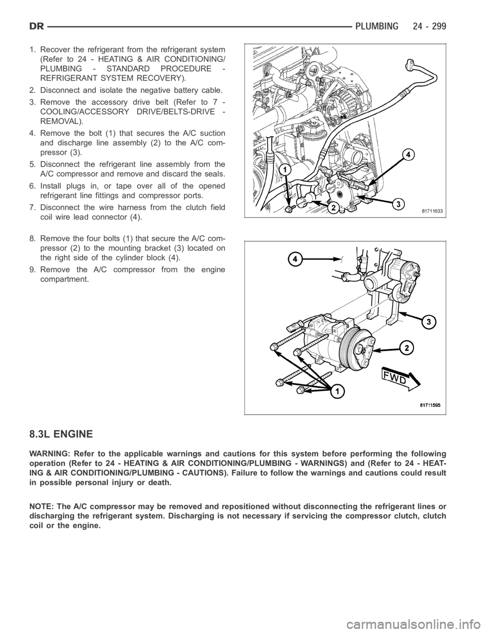
4. Remove the bolt (1) that secures the A/C suction
and discharge line assembly (2) to the A/C com-
pressor (3).
5. Disconnect the refrigerant line assembly from the
A/C compressor and remove and discard the seals.
6. Install plugs in, or tape over all of the opened
refrigerant line fittings and compressor ports.
7. Disconnect the wire harness from the clutch field
coil wire lead connector (4).
8. Remove the four bolts (1) that secure the A/C com-
pressor (2) to the mounting bracket (3) located on
the right side of the cylinder block (4).
9. Remove the A/C compressor from the engine
compartment.
8.3L ENGINE
WARNING: Refer to the applicable warnings and cautions for this system before performing the following
operation (Refer to 24 - HEATING & AIR CONDITIONING/PLUMBING - WARNINGS) and (Refer to 24 - HEAT-
ING & AIR CONDITIONING/PLUMBING - CAUTIONS). Failure to follow the warnings and cautions could result
in possible personal injury or death.
NOTE: The A/C compressor may be removed and repositioned without disconnecting the refrigerant lines or
discharging the refrigerant system. Discharging is not necessary if servicing the compressor clutch, clutch
coil or the engine.
Page 5141 of 5267
1. Recover the refrigerant from the refrigerant system
(Refer to 24 - HEATING & AIR CONDITIONING/
PLUMBING - STANDARD PROCEDURE -
REFRIGERANT SYSTEM RECOVERY).
2. Disconnect and isolate the negative battery cable.
3. Remove the accessory drive belt (Refer to 7 -
COOLING/ACCESSORY DRIVE/BELTS-DRIVE -
REMOVAL).
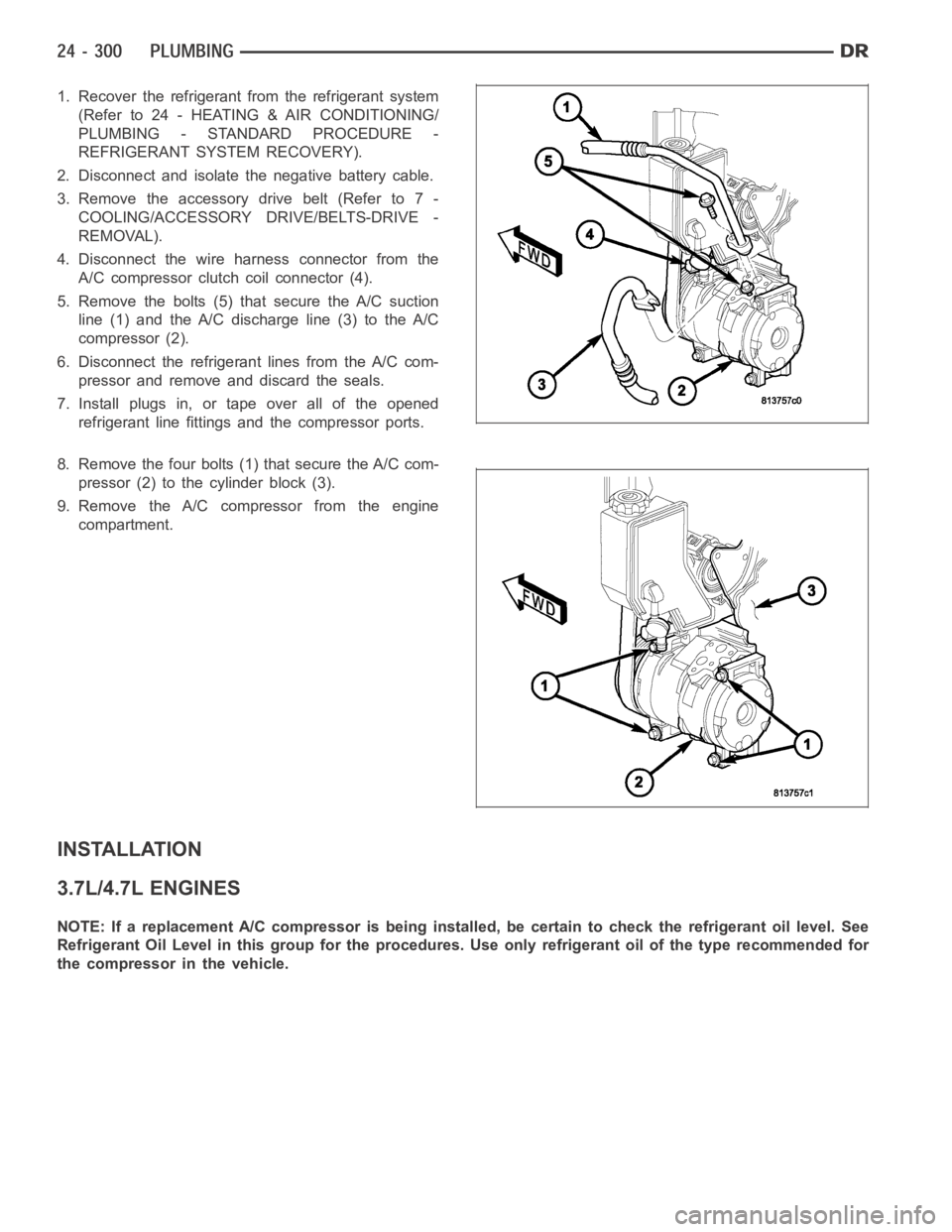
4. Disconnect the wire harness connector from the
A/C compressor clutch coil connector (4).
5. Remove the bolts (5) that secure the A/C suction
line (1) and the A/C discharge line (3) to the A/C
compressor (2).
6. Disconnect the refrigerant lines from the A/C com-
pressor and remove and discard the seals.
7. Install plugs in, or tape over all of the opened
refrigerant line fittings and the compressor ports.
8. Remove the four bolts (1) that secure the A/C com-
pressor (2) to the cylinder block (3).
9. Remove the A/C compressor from the engine
compartment.
INSTALLATION
3.7L/4.7L ENGINES
NOTE: If a replacement A/C compressor is being installed, be certain to check the refrigerant oil level. See
Refrigerant Oil Level in this group for the procedures. Use only refrigerant oil of the type recommended for
the compressor in the vehicle.
Page 5144 of 5267
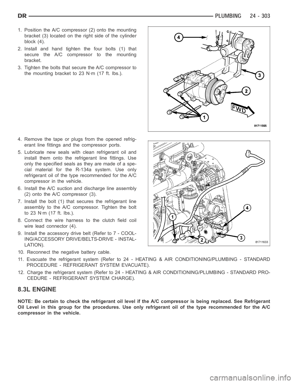
1. Position the A/C compressor (2) onto the mounting
bracket (3) located on the right side of the cylinder
block (4).
2. Install and hand tighten the four bolts (1) that
secure the A/C compressor to the mounting
bracket.
3. Tighten the bolts that secure the A/C compressor to
themountingbracketto23Nꞏm(17ft.lbs.).
4. Remove the tape or plugs from the opened refrig-
erant line fittings and the compressor ports.
5. Lubricate new seals with clean refrigerant oil and
install them onto the refrigerant line fittings. Use
only the specified seals as they are made of a spe-
cial material for the R-134a system. Use only
refrigerant oil of the type recommended for the A/C
compressor in the vehicle.
6. Install the A/C suction and discharge line assembly
(2) onto the A/C compressor (3).
7. Install the bolt (1) that secures the refrigerant line
assembly to the A/C compressor. Tighten the bolt
to 23 Nꞏm (17 ft. lbs.).
8. Connect the wire harness to the clutch field coil
wire lead connector (4).
9. Install the accessory drive belt (Refer to 7 - COOL-
ING/ACCESSORY DRIVE/BELTS-DRIVE - INSTAL-
LATION).
10. Reconnect the negative battery cable.
11. Evacuate the refrigerant system (Refer to 24 - HEATING & AIR CONDITIONING/PLUMBING - STANDARD
PROCEDURE - REFRIGERANT SYSTEM EVACUATE).
12. Charge the refrigerant system (Refer to 24 - HEATING & AIR CONDITIONING/PLUMBING - STANDARD PRO-
CEDURE - REFRIGERANT SYSTEM CHARGE).
8.3L ENGINE
NOTE: Be certain to check the refrigerant oil level if the A/C compressor isbeing replaced. See Refrigerant
Oil Level in this group for the procedures. Use only refrigerant oil of the type recommended for the A/C
compressor in the vehicle.