2006 DODGE RAM SRT-10 air condition
[x] Cancel search: air conditionPage 5083 of 5267
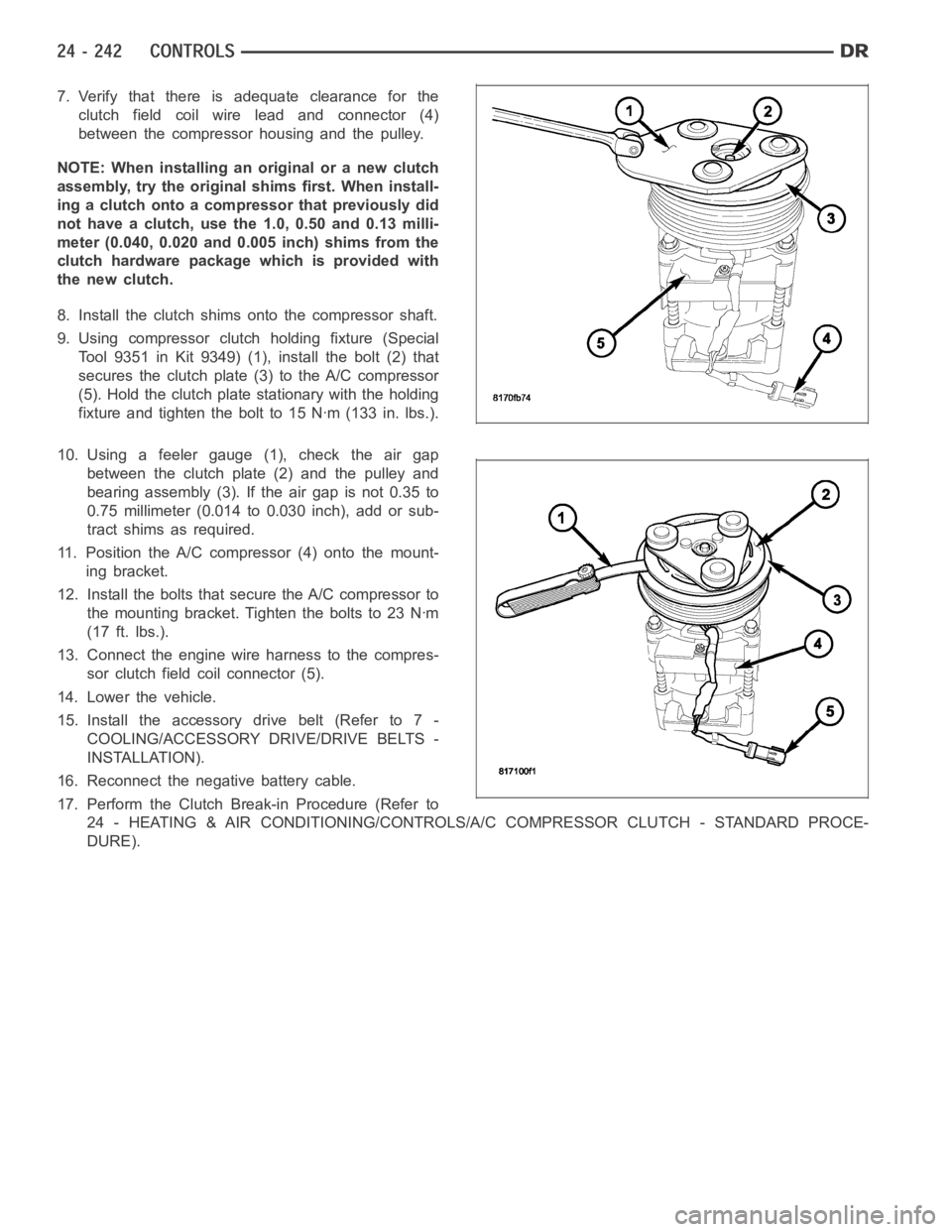
7. Verify that there is adequate clearance for the
clutch field coil wire lead and connector (4)
between the compressor housing and the pulley.
NOTE: When installing an original or a new clutch
assembly, try the original shims first. When install-
ing a clutch onto a compressor that previously did
not have a clutch, use the 1.0, 0.50 and 0.13 milli-
meter (0.040, 0.020 and 0.005 inch) shims from the
clutch hardware package which is provided with
the new clutch.
8. Install the clutch shims onto the compressor shaft.
9. Using compressor clutch holding fixture (Special
Tool 9351 in Kit 9349) (1), install the bolt (2) that
secures the clutch plate (3) to the A/C compressor
(5). Hold the clutch plate stationary with the holding
fixture and tighten the bolt to 15 Nꞏm (133 in. lbs.).
10. Using a feeler gauge (1), check the air gap
between the clutch plate (2) and the pulley and
bearing assembly (3). If the air gap is not 0.35 to
0.75 millimeter (0.014 to 0.030 inch), add or sub-
tract shims as required.
11. Position the A/C compressor (4) onto the mount-
ing bracket.
12. Install the bolts that secure the A/C compressor to
themountingbracket.Tightentheboltsto23Nꞏm
(17 ft. lbs.).
13. Connect the engine wire harness to the compres-
sor clutch field coil connector (5).
14. Lower the vehicle.
15. Install the accessory drive belt (Refer to 7 -
COOLING/ACCESSORY DRIVE/DRIVE BELTS -
INSTALLATION).
16. Reconnect the negative battery cable.
17. Perform the Clutch Break-in Procedure (Refer to
24 - HEATING & AIR CONDITIONING/CONTROLS/A/C COMPRESSOR CLUTCH - STANDARD PROCE-
DURE).
Page 5084 of 5267
CONTROL-A/C HEATER
DESCRIPTION
MANUAL SINGLE ZONE
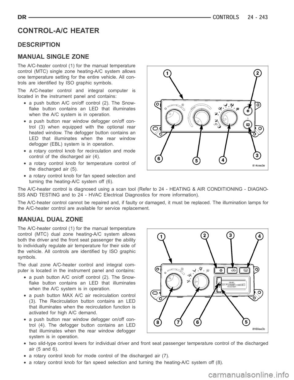
The A/C-heater control (1) for the manual temperature
control (MTC) single zoneheating-A/C system allows
one temperature setting for the entire vehicle. All con-
trols are identified by ISO graphic symbols.
The A/C-heater control and integral computer is
located in the instrument panel and contains:
a push button A/C on/off control (2). The Snow-
flake button contains an LED that illuminates
when the A/C system is in operation.
a push button rear window defogger on/off con-
trol (3) when equipped with the optional rear
heated window. The defogger button contains an
LED that illuminates when the rear window
defogger (EBL) system is in operation.
a rotary control knob for recirculation and mode
control of the discharged air (4).
a rotary control knob for temperature control of
thedischargedair(5).
a rotary control knob for fan speed selection and
turning the heating-A/C system off (6).
The A/C-heater control is diagnosed using a scan tool (Refer to 24 - HEATING& AIR CONDITIONING - DIAGNO-
SIS AND TESTING and to 24 - HVAC Electrical Diagnostics for more information).
The A/C-heater control cannot be repaired and, if faulty or damaged, it must be replaced. The illumination lamps for
the A/C-heater control are available for service replacement.
MANUAL DUAL ZONE
The A/C-heater control (1) for the manual temperature
control (MTC) dual zone heating-A/C system allows
both the driver and the front seat passenger the ability
to individually regulate air temperature for their side of
the vehicle. All controls are identified by ISO graphic
symbols.
The dual zone A/C-heater control and integral com-
puter is located in the instrument panel and contains:
a push button A/C on/off control (2). The Snow-
flake button contains an LED that illuminates
when the A/C system is in operation.
a push button MAX A/C air recirculation control
(3). The Recirculation button contains an LED
that illuminates when the recirculation function is
activated for high A/C demand.
a push button rear window defogger on/off con-
trol (4). The defogger button contains an LED
that illuminates when the rear window defogger
system is in operation.
two slid-type control levers for individual driver and front seat passenger temperature control of the discharged
air (5 and 6).
a rotary control knob for mode control of the discharged air (7).
a rotary control knob for fan speed selection and turning the heating-A/C system off (8).
Page 5085 of 5267
The A/C-heater control is diagnosed using a scan tool (Refer to 24 - HEATING& AIR CONDITIONING - DIAGNO-
SIS AND TESTING and to 24 - HVAC Electrical Diagnostics for more information).
The A/C-heater control cannot be repaired and, if faulty or damaged, it must be replaced. The illumination lamps for
the A/C-heater control are available for service replacement.
REMOVAL
WARNING: On vehicles equipped with airbags, disable the airbag system before attempting any steering
wheel, steering column, or instrument panel component diagnosis or service. Disconnect and isolate the
battery negative (ground) cable, then wait two minutes for the airbag system capacitor to discharge before
performing further diagnosis or service. This is the only sure way to disable the airbag system. Failure to
take the proper precautions could result in an accidental airbag deployment and possible personal injury or
death.
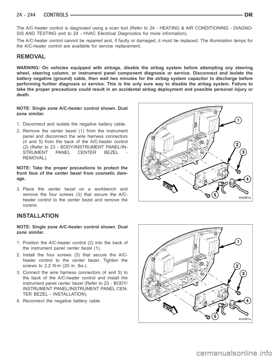
NOTE: Single zone A/C-heater control shown. Dual
zone similar.
1. Disconnect and isolate the negative battery cable.
2. Remove the center bezel (1) from the instrument
panel and disconnect the wire harness connectors
(4 and 5) from the back of the A/C-heater control
(2) (Refer to 23 - BODY/INSTRUMENT PANEL/IN-
STRUMENT PANEL CENTER BEZEL -
REMOVAL).
NOTE: Take the proper precautions to protect the
front face of the center bezel from cosmetic dam-
age.
3. Place the center bezel on a workbench and
remove the four screws (3) that secure the A/C-
heater control to the center bezel and remove the
control.
INSTALLATION
NOTE: Single zone A/C-heater control shown. Dual
zone similar.
1. Position the A/C-heater control (2) into the back of
the instrument panel center bezel (1).
2. Install the four screws (3) that secure the A/C-
heater control to the center bezel. Tighten the
screws to 2.2 Nꞏm (20 in. lbs.).
3. Connect the wire harness connectors (4 and 5) to
the back of the A/C-heater control and install the
instrument panel center bezel (Refer to 23 - BODY/
INSTRUMENT PANEL/INSTRUMENT PANEL CEN-
TER BEZEL - INSTALLATION).
4. Reconnect the negative battery cable.
Page 5089 of 5267
SENSOR-EVAPORATOR TEMPERATURE
DESCRIPTION
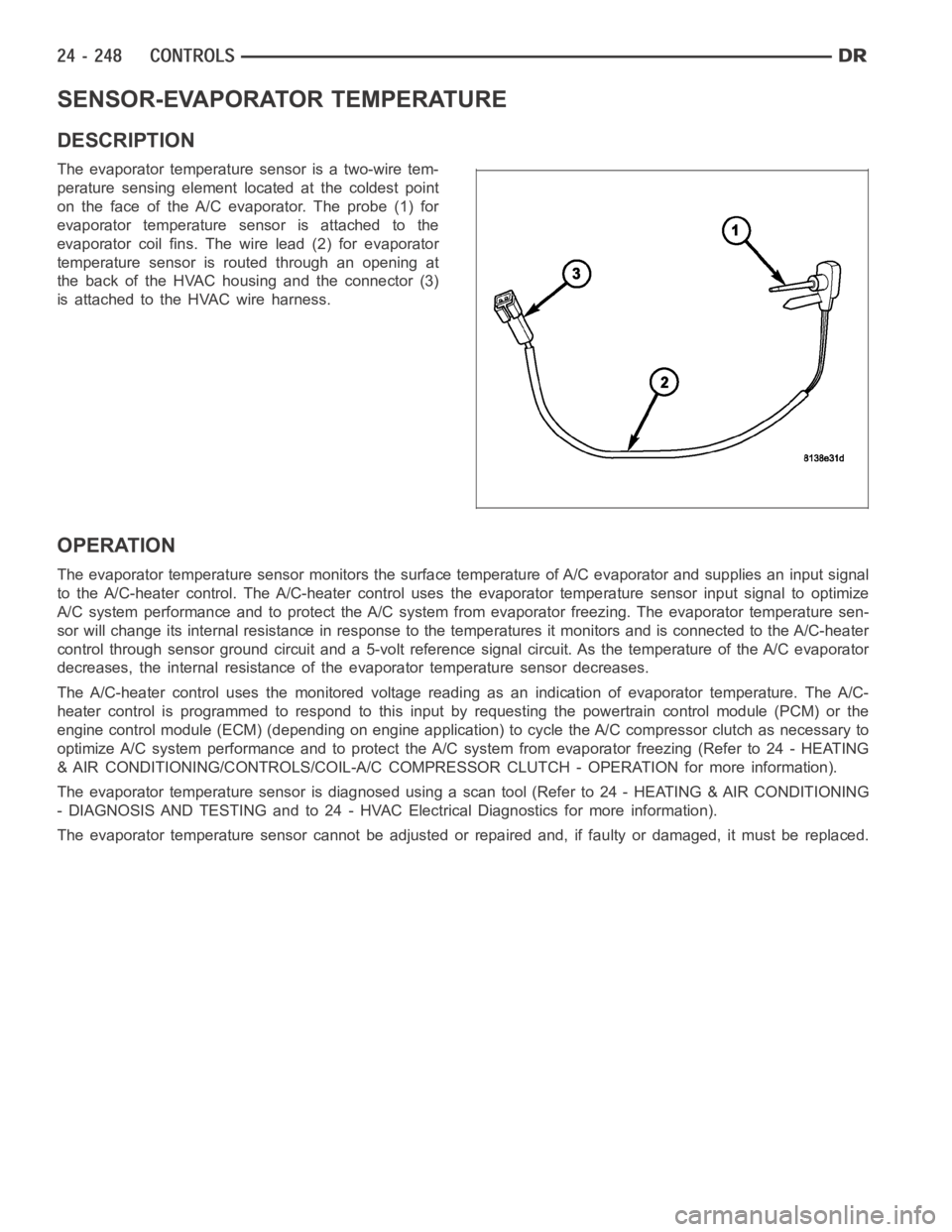
The evaporator temperature sensor is a two-wire tem-
perature sensing element located at the coldest point
on the face of the A/C evaporator. The probe (1) for
evaporator temperature sensor is attached to the
evaporator coil fins. The wire lead (2) for evaporator
temperature sensor is routed through an opening at
the back of the HVAC housing and the connector (3)
is attached to the HVAC wire harness.
OPERATION
The evaporator temperature sensor monitors the surface temperature of A/C evaporator and supplies an input signal
to the A/C-heater control. The A/C-heater control uses the evaporator temperature sensor input signal to optimize
A/C system performance and to protect the A/C system from evaporator freezing. The evaporator temperature sen-
sor will change its internal resistance in response to the temperatures itmonitors and is connected to the A/C-heater
control through sensor ground circuit and a 5-volt reference signal circuit. As the temperature of the A/C evaporator
decreases, the internal resistance of the evaporator temperature sensordecreases.
The A/C-heater control uses the monitored voltage reading as an indication of evaporator temperature. The A/C-
heater control is programmed to respond to this input by requesting the powertrain control module (PCM) or the
engine control module (ECM) (depending on engine application) to cycle the A/C compressor clutch as necessary to
optimize A/C system performance and to protect the A/C system from evaporatorfreezing(Referto24-HEATING
& AIR CONDITIONING/CONTROLS/COIL-A/C COMPRESSOR CLUTCH - OPERATION formore information).
The evaporator temperature sensor is diagnosed using a scan tool (Refer to24 - HEATING & AIR CONDITIONING
- DIAGNOSIS AND TESTING and to 24 - HVAC Electrical Diagnostics for more information).
The evaporator temperature sensor cannot be adjusted or repaired and, if faulty or damaged, it must be replaced.
Page 5090 of 5267
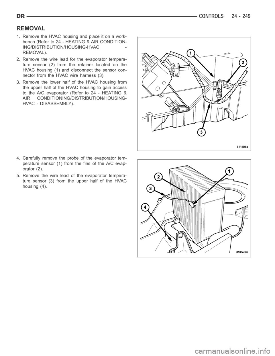
REMOVAL
1. RemovetheHVAChousingandplaceitonawork-
bench (Refer to 24 - HEATING & AIR CONDITION-
ING/DISTRIBUTION/HOUSING-HVAC -
REMOVAL).
2. Remove the wire lead for the evaporator tempera-
ture sensor (2) from the retainer located on the
HVAC housing (1) and disconnect the sensor con-
nector from the HVAC wire harness (3).
3. Remove the lower half of the HVAC housing from
the upper half of the HVAC housing to gain access
to the A/C evaporator (Refer to 24 - HEATING &
AIR CONDITIONING/DISTRIBUTION/HOUSING-
HVAC - DISASSEMBLY).
4. Carefully remove the probe of the evaporator tem-
perature sensor (1) from the fins of the A/C evap-
orator (2).
5. Remove the wire lead of the evaporator tempera-
ture sensor (3) from the upper half of the HVAC
housing (4).
Page 5091 of 5267
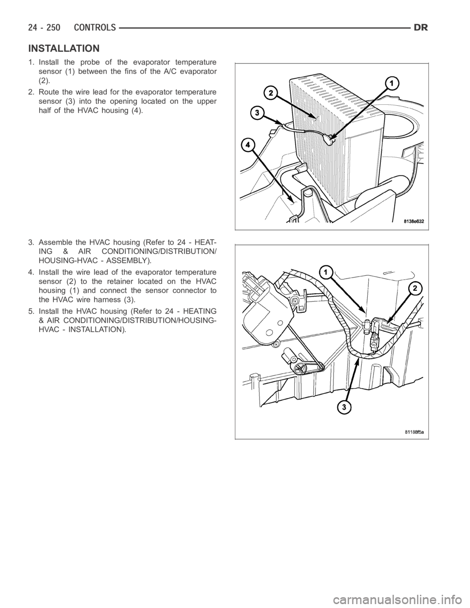
INSTALLATION
1. Install the probe of the evaporator temperature
sensor (1) between the fins of the A/C evaporator
(2).
2. Route the wire lead for the evaporator temperature
sensor (3) into the opening located on the upper
half of the HVAC housing (4).
3. Assemble the HVAC housing (Refer to 24 - HEAT-
ING & AIR CONDITIONING/DISTRIBUTION/
HOUSING-HVAC - ASSEMBLY).
4. Install the wire lead of the evaporator temperature
sensor (2) to the retainer located on the HVAC
housing (1) and connect the sensor connector to
theHVACwireharness(3).
5. Install the HVAC housing (Refer to 24 - HEATING
& AIR CONDITIONING/DISTRIBUTION/HOUSING-
HVAC - INSTALLATION).
Page 5098 of 5267
DUCT-FLOOR DISTRIBUTION
REMOVAL
WARNING: On vehicles equipped with airbags, disable the airbag system before attempting any steering
wheel, steering column, or instrument panel component diagnosis or service. Disconnect and isolate the
battery negative (ground) cable, then wait two minutes for the airbag system capacitor to discharge before
performing further diagnosis or service. This is the only sure way to disable the airbag system. Failure to
take the proper precautions could result in an accidental airbag deployment and possible personal injury or
death.
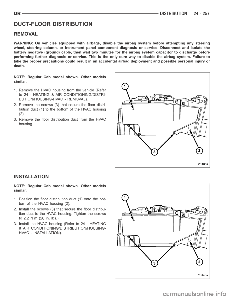
NOTE: Regular Cab model shown. Other models
similar.
1. Remove the HVAC housing from the vehicle (Refer
to 24 - HEATING & AIR CONDITIONING/DISTRI-
BUTION/HOUSING-HVAC - REMOVAL).
2. Remove the screws (3) that secure the floor distri-
bution duct (1) to the bottom of the HVAC housing
(2).
3. Remove the floor distribution duct from the HVAC
housing.
INSTALLATION
NOTE: Regular Cab model shown. Other models
similar.
1. Position the floor distribution duct (1) onto the bot-
tom of the HVAC housing (2).
2. Install the screws (3) that secure the floor distribu-
tion duct to the HVAC housing. Tighten the screws
to 2.2 Nꞏm (20 in. lbs.).
3. Install the HVAC housing (Refer to 24 - HEATING
& AIR CONDITIONING/DISTRIBUTION/HOUSING-
HVAC - INSTALLATION).
Page 5099 of 5267
DUCT-INSTRUMENT PANEL
REMOVAL
WARNING: On vehicles equipped with airbags, disable the airbag system before attempting any steering
wheel, steering column, or instrument panel component diagnosis or service. Disconnect and isolate the
battery negative (ground) cable, then wait two minutes for the airbag system capacitor to discharge before
performing further diagnosis or service. This is the only sure way to disable the airbag system. Failure to
take the proper precautions could result in an accidental airbag deployment and possible personal injury or
death.
NOTE: Take the proper precautions to protect the instrument panel from cosmetic damage.
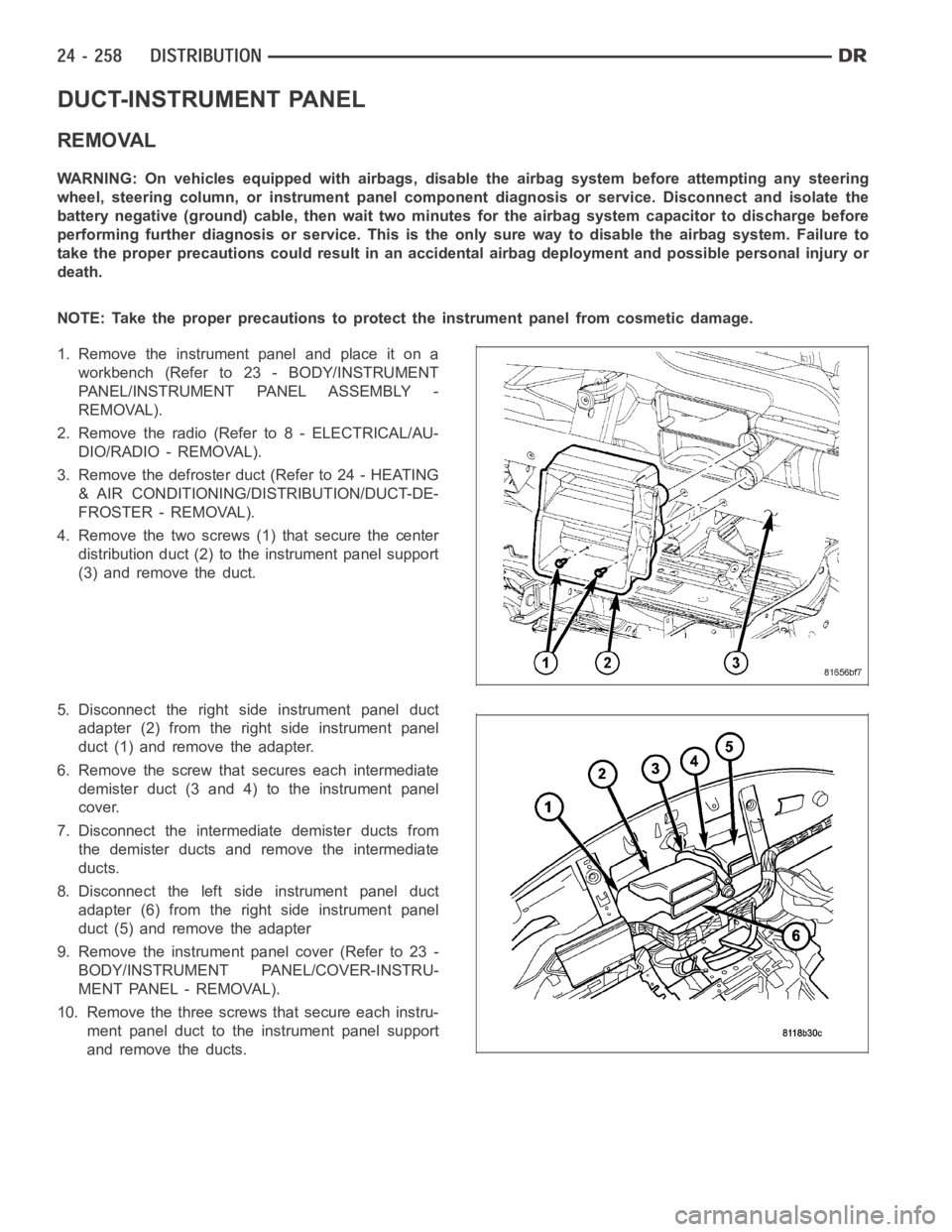
1. Remove the instrument panel and place it on a
workbench (Refer to 23 - BODY/INSTRUMENT
PANEL/INSTRUMENT PANEL ASSEMBLY -
REMOVAL).
2. Remove the radio (Refer to 8 - ELECTRICAL/AU-
DIO/RADIO - REMOVAL).
3. Remove the defroster duct (Refer to 24 - HEATING
& AIR CONDITIONING/DISTRIBUTION/DUCT-DE-
FROSTER - REMOVAL).
4. Remove the two screws (1) that secure the center
distribution duct (2) to the instrument panel support
(3) and remove the duct.
5. Disconnect the right side instrument panel duct
adapter (2) from the right side instrument panel
duct (1) and remove the adapter.
6. Remove the screw that secures each intermediate
demister duct (3 and 4) to the instrument panel
cover.
7. Disconnect the intermediate demister ducts from
the demister ducts and remove the intermediate
ducts.
8. Disconnect the left side instrument panel duct
adapter (6) from the right side instrument panel
duct (5) and remove the adapter
9. Remove the instrument panel cover (Refer to 23 -
BODY/INSTRUMENT PANEL/COVER-INSTRU-
MENT PANEL - REMOVAL).
10. Remove the three screws that secure each instru-
ment panel duct to the instrument panel support
and remove the ducts.