2006 DODGE RAM SRT-10 air condition
[x] Cancel search: air conditionPage 5117 of 5267
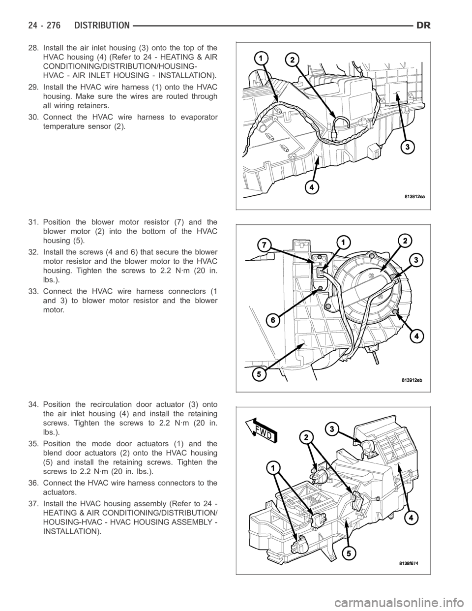
28. Install the air inlet housing (3) onto the top of the
HVAC housing (4) (Refer to 24 - HEATING & AIR
CONDITIONING/DISTRIBUTION/HOUSING-
HVAC - AIR INLET HOUSING - INSTALLATION).
29. Install the HVAC wire harness (1) onto the HVAC
housing. Make sure the wires are routed through
all wiring retainers.
30. Connect the HVAC wire harness to evaporator
temperature sensor (2).
31. Position the blower motor resistor (7) and the
blower motor (2) into the bottom of the HVAC
housing (5).
32. Install the screws (4 and 6) that secure the blower
motor resistor and the blower motor to the HVAC
housing. Tighten the screws to 2.2 Nꞏm (20 in.
lbs.).
33. Connect the HVAC wire harness connectors (1
and 3) to blower motor resistor and the blower
motor.
34. Position the recirculation door actuator (3) onto
the air inlet housing (4) and install the retaining
screws. Tighten the screws to 2.2 Nꞏm (20 in.
lbs.).
35. Position the mode door actuators (1) and the
blend door actuators (2) onto the HVAC housing
(5) and install the retaining screws. Tighten the
screws to 2.2 Nꞏm (20 in. lbs.).
36. Connect the HVAC wire harness connectors to the
actuators.
37. Install the HVAC housing assembly (Refer to 24 -
HEATING & AIR CONDITIONING/DISTRIBUTION/
HOUSING-HVAC - HVAC HOUSING ASSEMBLY -
INSTALLATION).
Page 5118 of 5267

AIR INLET HOUSING
NOTE: The air inlet housing must be removed from HVAC housing and disassembled for service of the
recirculation-air door.
NOTE: If the seals on the air door is deformed or
damaged, the air door must be replaced.
1. Position the recirculation-air door (1) into the air
inlet housing (2).
CAUTION: Make sure that the recirculation-air
door pivot shaft is properly seated in the pivot
seat located in the air inlet housing.
2. Align the actuator coupler (3) with the recirculation-
air door pivot shaft and install the coupler until the
coupler retaining tabs are fully engaged to the air
inlet housing. Be sure to install the coupler with the
coupler arm located between the two stop tabs on
the air inlet housing.
3. Install the two foam insulators (2) into the air inlet
housing (1).
4. Install the air inlet housing onto the HVAC housing
(Refer to 24 - HEATING & AIR CONDITIONING/
DISTRIBUTION/HOUSING-HVAC - AIR INLET
HOUSING - INSTALLATION).
INSTALLATION
HVAC HOUSING ASSEMBLY
NOTE: The HVAC housing must be removedfrom the vehicle and disassembled for service of the A/C evap-
orator, evaporator temperature sensor, mode-air and blend-air doors.
Page 5119 of 5267
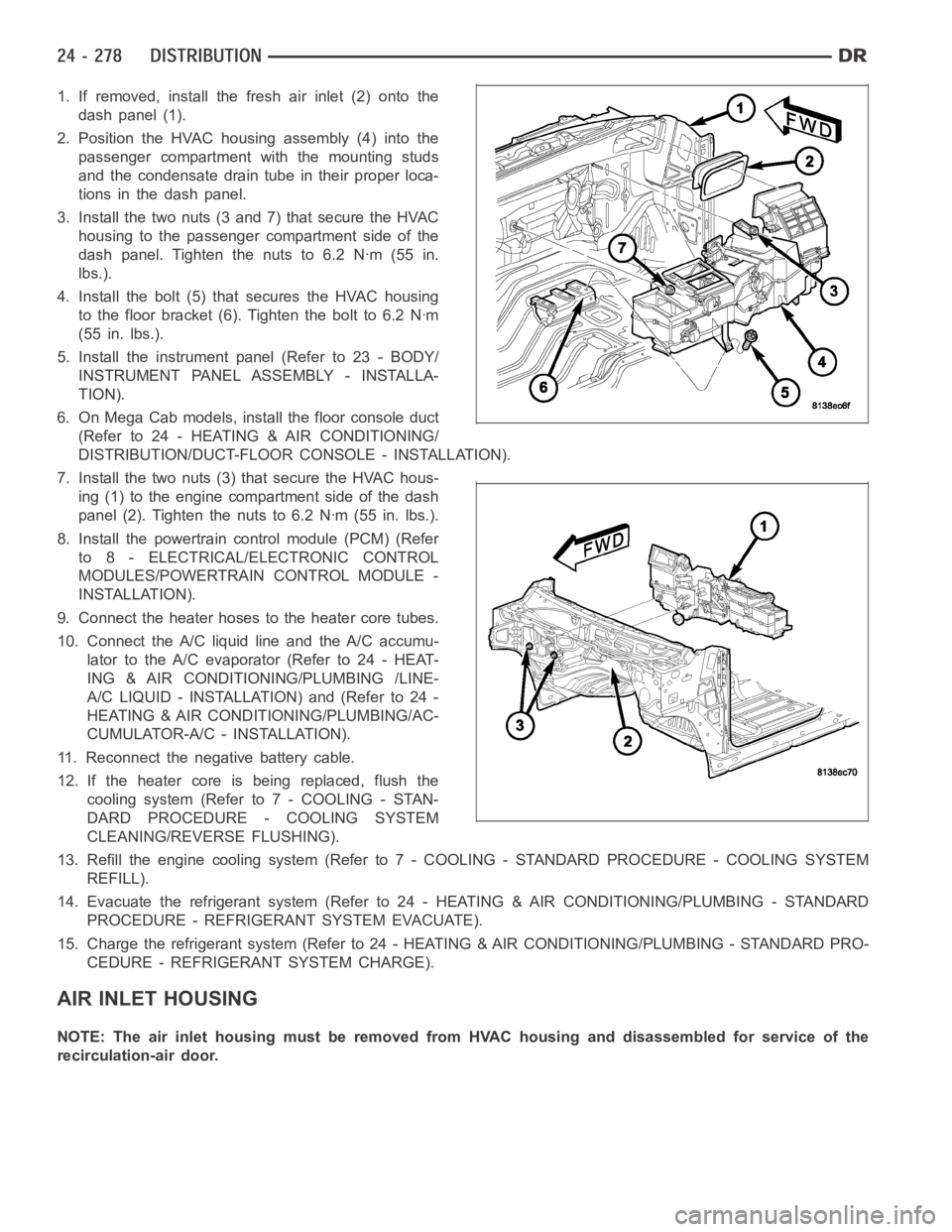
1. If removed, install the fresh air inlet (2) onto the
dash panel (1).
2. Position the HVAC housing assembly (4) into the
passenger compartment with the mounting studs
and the condensate drain tube in their proper loca-
tions in the dash panel.
3. Install the two nuts (3 and 7) that secure the HVAC
housing to the passenger compartment side of the
dash panel. Tighten the nuts to 6.2 Nꞏm (55 in.
lbs.).
4. Install the bolt (5) that secures the HVAC housing
to the floor bracket (6). Tighten the bolt to 6.2 Nꞏm
(55 in. lbs.).
5. Install the instrument panel (Refer to 23 - BODY/
INSTRUMENT PANEL ASSEMBLY - INSTALLA-
TION).
6. On Mega Cab models, install the floor console duct
(Refer to 24 - HEATING & AIR CONDITIONING/
DISTRIBUTION/DUCT-FLOOR CONSOLE - INSTALLATION).
7. Install the two nuts (3) that secure the HVAC hous-
ing (1) to the engine compartment side of the dash
panel (2). Tighten the nuts to 6.2 Nꞏm (55 in. lbs.).
8. Install the powertrain control module (PCM) (Refer
to 8 - ELECTRICAL/ELECTRONIC CONTROL
MODULES/POWERTRAIN CONTROL MODULE -
INSTALLATION).
9. Connect the heater hoses to the heater core tubes.
10. Connect the A/C liquid line and the A/C accumu-
lator to the A/C evaporator (Refer to 24 - HEAT-
ING & AIR CONDITIONING/PLUMBING /LINE-
A/C LIQUID - INSTALLATION) and (Refer to 24 -
HEATING & AIR CONDITIONING/PLUMBING/AC-
CUMULATOR-A/C - INSTALLATION).
11. Reconnect the negative battery cable.
12. If the heater core is being replaced, flush the
coolingsystem(Referto7-COOLING-STAN-
DARD PROCEDURE - COOLING SYSTEM
CLEANING/REVERSE FLUSHING).
13. Refill the engine cooling system (Refer to 7 - COOLING - STANDARD PROCEDURE - COOLING SYSTEM
REFILL).
14. Evacuate the refrigerant system (Refer to 24 - HEATING & AIR CONDITIONING/PLUMBING - STANDARD
PROCEDURE - REFRIGERANT SYSTEM EVACUATE).
15. Charge the refrigerant system (Refer to 24 - HEATING & AIR CONDITIONING/PLUMBING - STANDARD PRO-
CEDURE - REFRIGERANT SYSTEM CHARGE).
AIR INLET HOUSING
NOTE: The air inlet housing must be removed from HVAC housing and disassembled for service of the
recirculation-air door.
Page 5120 of 5267
NOTE: If the foam seal on the air inlet housing is
deformed or damaged, it must be replaced.
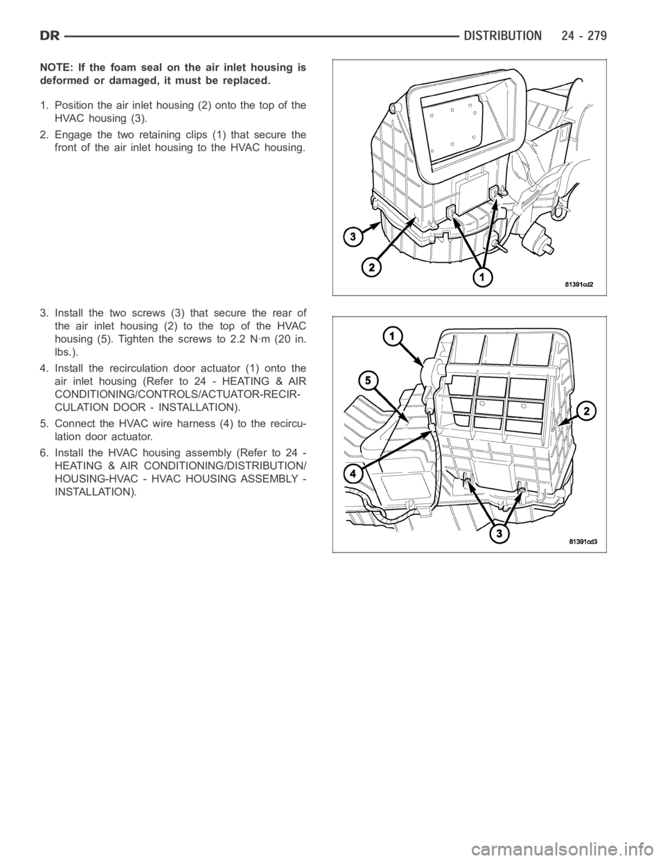
1. Position the air inlet housing (2) onto the top of the
HVAC housing (3).
2. Engage the two retaining clips (1) that secure the
front of the air inlet housing to the HVAC housing.
3. Install the two screws (3) that secure the rear of
the air inlet housing (2) to the top of the HVAC
housing (5). Tighten the screws to 2.2 Nꞏm (20 in.
lbs.).
4. Install the recirculation door actuator (1) onto the
air inlet housing (Refer to 24 - HEATING & AIR
CONDITIONING/CONTROLS/ACTUATOR-RECIR-
CULATION DOOR - INSTALLATION).
5. Connect the HVAC wire harness (4) to the recircu-
lation door actuator.
6. Install the HVAC housing assembly (Refer to 24 -
HEATING & AIR CONDITIONING/DISTRIBUTION/
HOUSING-HVAC - HVAC HOUSING ASSEMBLY -
INSTALLATION).
Page 5121 of 5267
MOTOR-BLOWER
DESCRIPTION
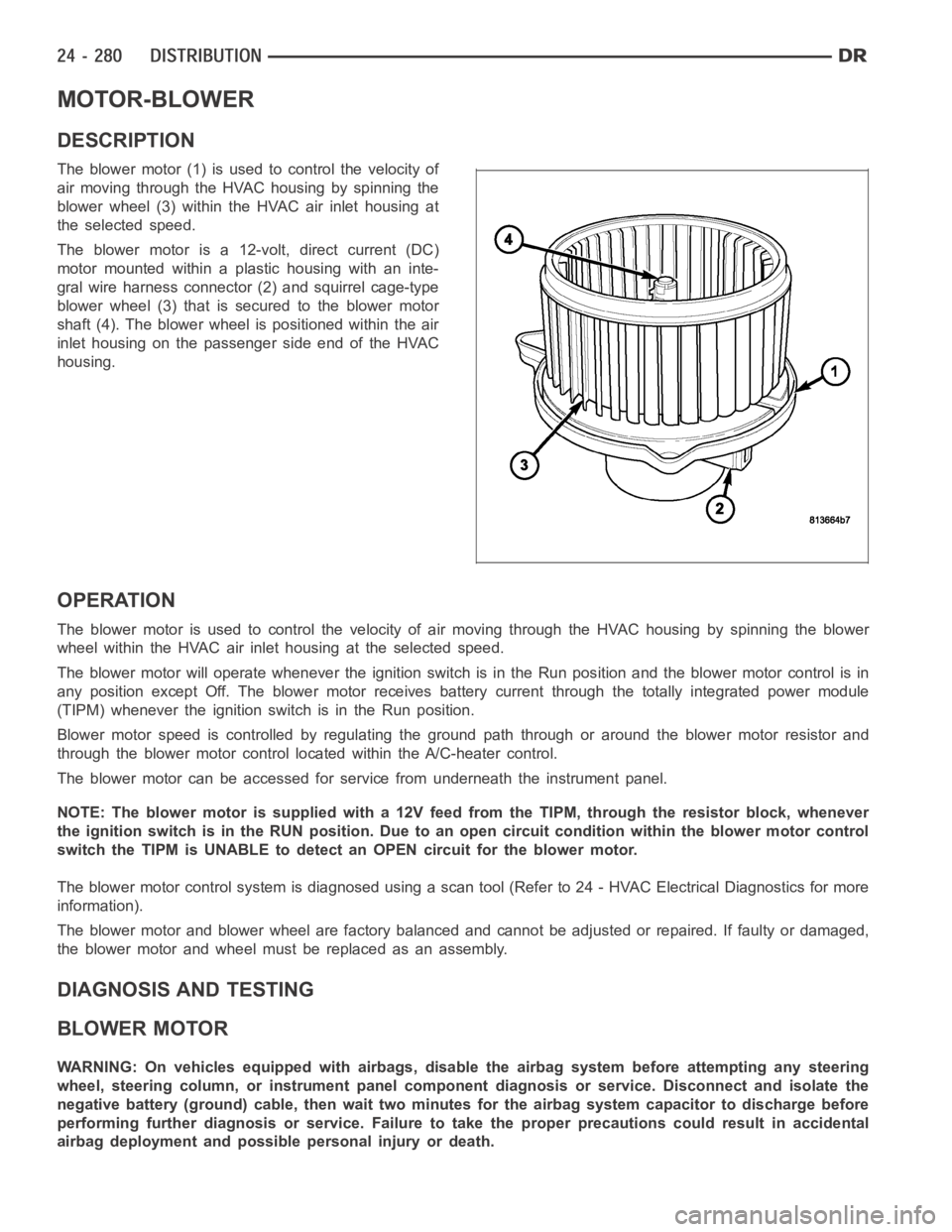
The blower motor (1) is used to control the velocity of
air moving through the HVAC housing by spinning the
blower wheel (3) within the HVAC air inlet housing at
the selected speed.
The blower motor is a 12-volt, direct current (DC)
motormountedwithinaplastichousingwithaninte-
gral wire harness connector (2) and squirrel cage-type
blower wheel (3) that is secured to the blower motor
shaft (4). The blower wheel is positioned within the air
inlet housing on the passenger side end of the HVAC
housing.
OPERATION
The blower motor is used to control the velocity of air moving through the HVAC housing by spinning the blower
wheel within the HVAC air inlet housing at the selected speed.
The blower motor will operate whenever the ignition switch is in the Run position and the blower motor control is in
any position except Off. The blower motor receives battery current through the totally integrated power module
(TIPM) whenever the ignition switch is in the Run position.
Blower motor speed is controlled by regulating the ground path through or around the blower motor resistor and
through the blower motor control located within the A/C-heater control.
The blower motor can be accessed for service from underneath the instrument panel.
NOTE: The blower motor is supplied with a 12V feed from the TIPM, through theresistor block, whenever
the ignition switch is in the RUN position. Due to an open circuit conditionwithin the blower motor control
switch the TIPM is UNABLE to detect an OPEN circuit for the blower motor.
The blower motor control system is diagnosed using a scan tool (Refer to 24 -HVAC Electrical Diagnostics for more
information).
The blower motor and blower wheel are factory balanced and cannot be adjusted or repaired. If faulty or damaged,
the blower motor and wheel must be replaced as an assembly.
DIAGNOSIS AND TESTING
BLOWER MOTOR
WARNING: On vehicles equipped with airbags, disable the airbag system before attempting any steering
wheel, steering column, or instrument panel component diagnosis or service. Disconnect and isolate the
negative battery (ground) cable, then wait two minutes for the airbag system capacitor to discharge before
performing further diagnosis or service. Failure to take the proper precautions could result in accidental
airbag deployment and possible personal injury or death.
Page 5122 of 5267
NOTE: The blower motor is supplied with a 12V feed from the TIPM, through theresistor block, whenever
the ignition switch is in the RUN position. Due to an open circuit conditionwithin the blower motor control
switch the TIPM is UNABLE to detect an OPEN circuit for the blower motor.
To determine if an open condition exists within the blower motor circuit wiring, it is necessary to disconnect the
negative battery cable and check for continuity within the blower motor circuits using an ohmmeter. For circuit
descriptions and diagrams, refer to Air Conditioning/Heater in Group 8W -Wiring Diagrams.
OPERATION
Possible causes of the blower motor not operating include:
Faulty blower motor
Faulty blower motor circuit wiring or wire harness connectors
Faulty blower motor control
Possible causes of the blower motor not operating in one or more speeds include:
Faulty blower motor resistor
Faulty blower motor circuit wiring or wire harness connectors
Faulty blower motor control
VIBRATION
Possible causes of blower motor vibration include:
Improper blower motor mounting
Improper blower wheel mounting
Deformed blower wheel
Out of balance blower wheel due to foreign material in the wheel
Faulty blower motor
NOISE
To determine if the blower motor is the source of the noise, simply switch the blower motor from Off to On. To verify
that the blower motor is the source of the noise, unplug the blower motor wire harness connector and operate the
heating-A/C system. If the noise goes away, possible causes include:
Foreign material in the HVAC air inlet housing
Improper blower motor mounting
Improper blower wheel mounting
Faulty blower motor
Page 5124 of 5267
OUTLETS-AIR
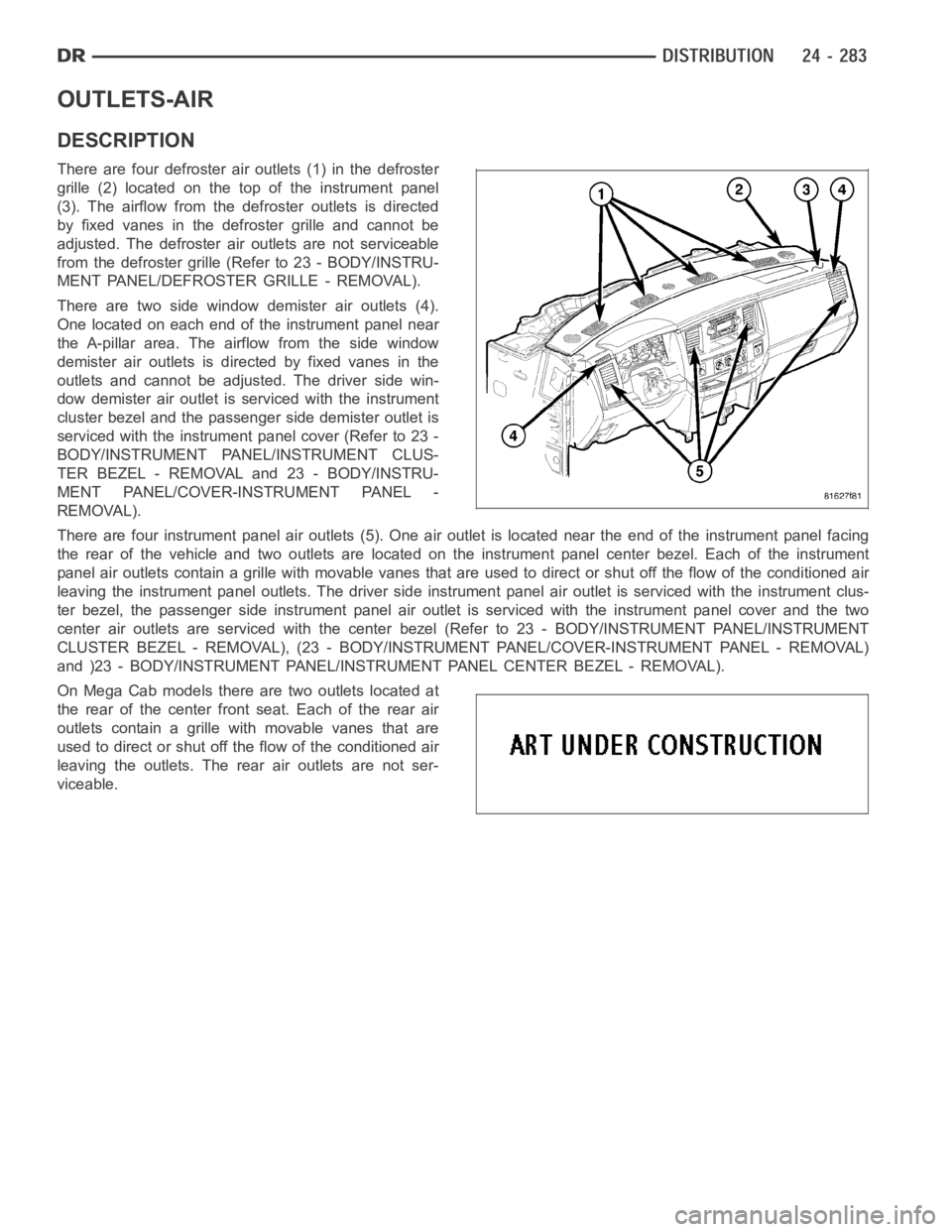
DESCRIPTION
There are four defroster air outlets (1) in the defroster
grille (2) located on the top of the instrument panel
(3). The airflow from the defroster outlets is directed
by fixed vanes in the defroster grille and cannot be
adjusted. The defroster air outlets are not serviceable
from the defroster grille (Refer to 23 - BODY/INSTRU-
MENT PANEL/DEFROSTER GRILLE - REMOVAL).
There are two side window demister air outlets (4).
One located on each end of the instrument panel near
the A-pillar area. The airflow from the side window
demister air outlets is directed by fixed vanes in the
outlets and cannot be adjusted. The driver side win-
dow demister air outlet is serviced with the instrument
cluster bezel and the passenger side demister outlet is
serviced with the instrument panel cover (Refer to 23 -
BODY/INSTRUMENT PANEL/INSTRUMENT CLUS-
TER BEZEL - REMOVAL and 23 - BODY/INSTRU-
MENT PANEL/COVER-INSTRUMENT PANEL -
REMOVAL).
There are four instrument panel air outlets (5). One air outlet is located near the end of the instrument panel facing
the rear of the vehicle and two outlets are located on the instrument panel center bezel. Each of the instrument
panel air outlets contain a grille with movable vanes that are used to direct or shut off the flow of the conditioned air
leaving the instrument panel outlets. The driver side instrument panel air outlet is serviced with the instrument clus-
ter bezel, the passenger side instrument panel air outlet is serviced withthe instrument panel cover and the two
center air outlets are serviced with the center bezel (Refer to 23 - BODY/INSTRUMENT PANEL/INSTRUMENT
CLUSTER BEZEL - REMOVAL), (23 - BODY/INSTRUMENT PANEL/COVER-INSTRUMENTPA N E L - R E M O VA L )
and )23 - BODY/INSTRUMENT PANEL/INSTRUMENT PANEL CENTER BEZEL - REMOVAL).
On Mega Cab models there are two outlets located at
the rear of the center front seat. Each of the rear air
outlets contain a grille withmovable vanes that are
used to direct or shut off the flow of the conditioned air
leaving the outlets. The rear air outlets are not ser-
viceable.
Page 5128 of 5267
WARNING: The engine cooling system is designed to develop internal pressures up to 145 kilopascals (21
pounds per square inch). Do not remove or loosen the coolant pressure cap, cylinder block drain plugs,
radiator drain, radiator hoses, heater hoses, or hose clamps while the engine cooling system is hot and
under pressure. Allow the vehicle to cool for a minimum of 15 minutes beforeopening the cooling system
for service. Failure to observe this warning can result in serious burns from the heated engine coolant.
CAUTION
CAUTION: Never add R-12 to a refrigerant system designed to use R-134a. Do not use R-12 equipment or
parts on an R-134a A/C system. These refrigerants are not compatible and damage to the A/C system will
result.
CAUTION: Never use R-12 refrigerant oil in a A/C system designed to use R-134a refrigerant oil. These
refrigerant oils are not compatible and damage to the A/C system will result.
CAUTION: The use of A/C system sealers may result in damage to A/C refrigerant recovery/evacuation/re-
charging equipment and/or A/C system. Many federal, state/provincial and local regulations prohibit the
recharge of A/C systems with known leaks. DaimlerChrysler recommends thedetection of A/C system leaks
through the use of approved leak detectors and fluorescent leak detectiondyes. Vehicles found with A/C
system sealers should be treated as contaminated and replacement of the entire A/C refrigerant system is
recommended. A/C systems found to be contaminated with A/C system sealers, A/C stop-leak products or
seal conditioners voids the warranty for the A/C system.
CAUTION: Recover the refrigerant before opening any fitting or connection. Open the fittings with caution,
even after the system has been discharged. Never open or loosen a connection before recovering the refrig-
erant.
CAUTION: If equipped, do not remove the secondary retention clip from any spring-lock coupler connection
while the refrigerant system is under pressure. Recover the refrigerant before removing the secondary
retention clip. Open the fittings with caution, even after the system has been discharged. Never open or
loosen a connection before recovering the refrigerant.
CAUTION: The internal parts of the A/C system will remain stable as long as moisture-free refrigerant and
refrigerant oil is used. Abnormal amounts of dirt, moisture or air can upset the chemical stability. This may
cause operational troubles or even serious damage if present in more than very small quantities. Before
disconnecting a component, clean the outside of the fittings thoroughly to prevent contamination from
entering the refrigerant system. Keep service tools and the work area clean. Do not open the refrigerant
system or uncap a replacement component until you are ready to service the system. Immediately after
disconnecting a component from the refrigerant system, seal the open fittings with a cap or plug. This will
prevent contamination from entering the A/C system.
CAUTION: Refrigerant oil will absorb moisture from the atmosphere if leftuncapped. Do not open a con-
tainer of refrigerant oil until you are ready to use it. Replace the cap on the oil container immediately after
using. Store refrigerant oil only in a clean, airtight, and moisture-freecontainer.
CAUTION: Do not overcharge the refrigerant system. Overcharging will cause excessive compressor head
pressure and can cause compressor noise and A/C system failure.