Page 2925 of 5267

TORQUE CONVERTER LEAKAGE
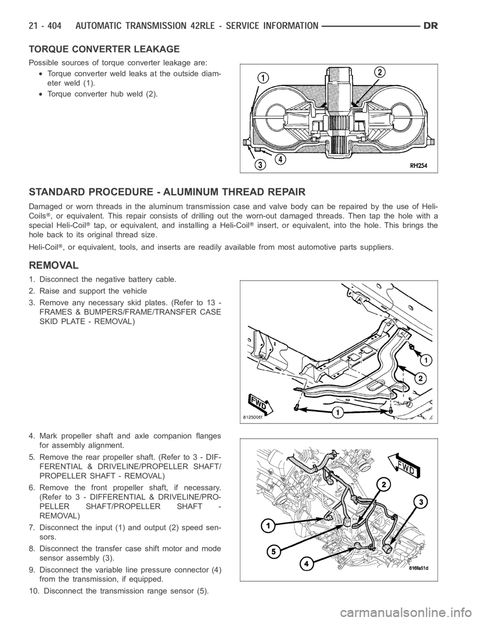
Possible sources of torque converter leakage are:
Torque converter weld leaks at the outside diam-
eter weld (1).
Torque converter hub weld (2).
STANDARD PROCEDURE - ALUMINUM THREAD REPAIR
DamagedorwornthreadsinthealuminumtransmissioncaseandvalvebodycanberepairedbytheuseofHeli-
Coils
, or equivalent. This repair consists of drilling out the worn-out damagedthreads. Then tap the hole with a
special Heli-Coil
tap, or equivalent, and installing a Heli-Coilinsert, or equivalent, into the hole. This brings the
hole back to its original thread size.
Heli-Coil
, or equivalent, tools, and inserts are readily available from most automotive parts suppliers.
REMOVAL
1. Disconnect the negative battery cable.
2. Raise and support the vehicle
3. Remove any necessary skid plates. (Refer to 13 -
FRAMES & BUMPERS/FRAME/TRANSFER CASE
SKID PLATE - REMOVAL)
4. Mark propeller shaft and axle companion flanges
for assembly alignment.
5. Remove the rear propeller shaft. (Refer to 3 - DIF-
FERENTIAL & DRIVELINE/PROPELLER SHAFT/
PROPELLER SHAFT - REMOVAL)
6. Remove the front propeller shaft, if necessary.
(Refer to 3 - DIFFERENTIAL & DRIVELINE/PRO-
PELLER SHAFT/PROPELLER SHAFT -
REMOVAL)
7. Disconnect the input (1) and output (2) speed sen-
sors.
8. Disconnect the transfer case shift motor and mode
sensor assembly (3).
9. Disconnect the variable line pressure connector (4)
from the transmission, if equipped.
10. Disconnect the transmission range sensor (5).
Page 2933 of 5267
NOTE: One of the oil pan bolts has a sealing patch
applied from the factory. Separate this bolt for
reuse.
14. Remove the transmission oil pan bolts (2).
15. Removethetransmissionoilpan(1).
16. Remove the transmission oil filter screws (2).
Page 2934 of 5267
17. Remove transmission oil filter (1).
18. Remove the oil filter o-ring (2) from the valve
body.
19. Remove valve body-to-case bolts (1).
Page 2938 of 5267
29. Remove oil pump gasket (2).
CAUTION: By-pass valve must be replaced if a
transmission failure has occured.
30. Remove the cooler by-pass valve (1).
31. Remove the #1 caged needle bearing (1).
Page 2963 of 5267
42. Remove the oil pump o-ring (2) and install oil
pump and gasket to transmission.Use screw-in
dowels or phillips-headscrewdrivers to align
pump to case. Be sure to reinstall O-ring on
oil pump after selecting the proper No. 4
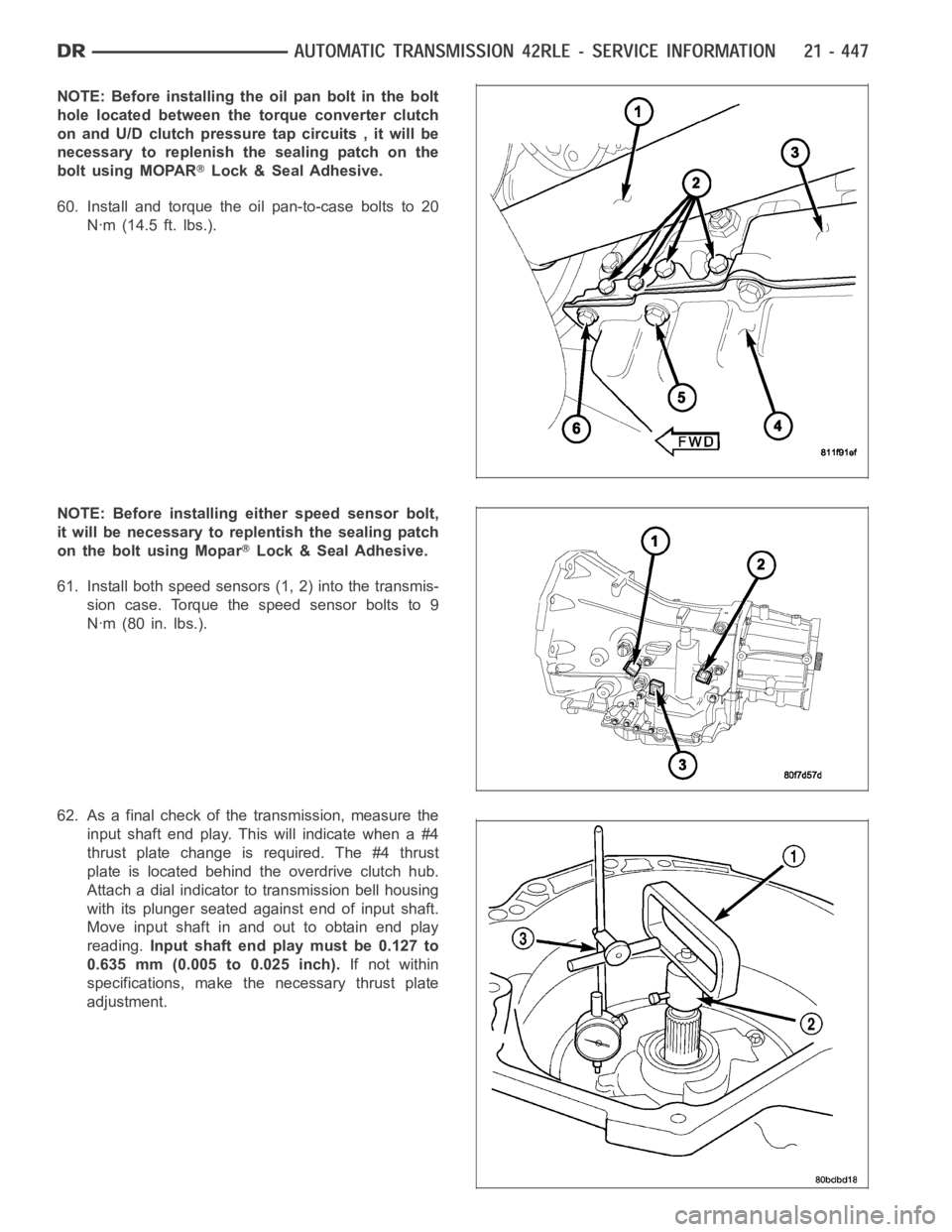
thrust plate.
43. Measure the input shaft end play with the trans-
mission in the vertical position. This will ensure
that the measurement will be accurate.
44. Set up and measure endplay using End Play Set
8266 (1, 2) and Dial Indicator Set C-3339 (3) as
shown.
45. Measure input shaft end play.Input shaft end
play must be 0.127 to 0.635 mm (0.005 to 0.025
inch).For example, if end play reading is 0.055
inch, select No. 4 Thrust Plate which is 0.071 to
0.074 thick. This should provide an input shaft
end play reading of 0.020 inch, which is within
specifications.
46. Remove oil pump, gasket, and input clutch
assembly to gain access to and install proper #4
thrust plate.
47. Install input clutch assembly (1) with proper thrust
plate.
Page 2964 of 5267
48. Install #1 caged needle bearing (1).
CAUTION: By-pass valve MUST be replaced if a
transmission failure has occured.
49. Replace cooler by-pass valve (1) if transmission
failure has occurred.
NOTE: To align oil pump, gasket, and case during
installation, use threadeddowels or phillips screw-
drivers.
50. Install oil pump gasket (2).
Page 2967 of 5267
57. Install seven (7) valve body-to-case bolts (1) and
torque to 12 Nꞏm (105 in. lbs.).
58. Install transmission oil filter (1). Tighten the bolts
to5Nꞏm(45in.lbs.).
59. Install transmission oil pan (1) with a bead of
Mopar
AT F R T V.
Page 2968 of 5267

NOTE: Before installing the oil pan bolt in the bolt
hole located between the torque converter clutch
on and U/D clutch pressure tap circuits , it will be
necessary to replenish the sealing patch on the
bolt using MOPAR
Lock & Seal Adhesive.
60. Install and torque the oil pan-to-case bolts to 20
Nꞏm (14.5 ft. lbs.).
NOTE: Before installing either speed sensor bolt,
it will be necessary to replentish the sealing patch
on the bolt using Mopar
Lock & Seal Adhesive.
61. Install both speed sensors (1, 2) into the transmis-
sion case. Torque the speed sensor bolts to 9
Nꞏm (80 in. lbs.).
62. As a final check of the transmission, measure the
input shaft end play. This will indicate when a #4
thrust plate change is required. The #4 thrust
plate is located behind the overdrive clutch hub.
Attach a dial indicator to transmission bell housing
with its plunger seated against end of input shaft.
Move input shaft in and out to obtain end play
reading.Input shaft end play must be 0.127 to
0.635 mm (0.005 to 0.025 inch).If not within
specifications, make the necessary thrust plate
adjustment.