2006 DODGE RAM SRT-10 transmission oil
[x] Cancel search: transmission oilPage 2972 of 5267
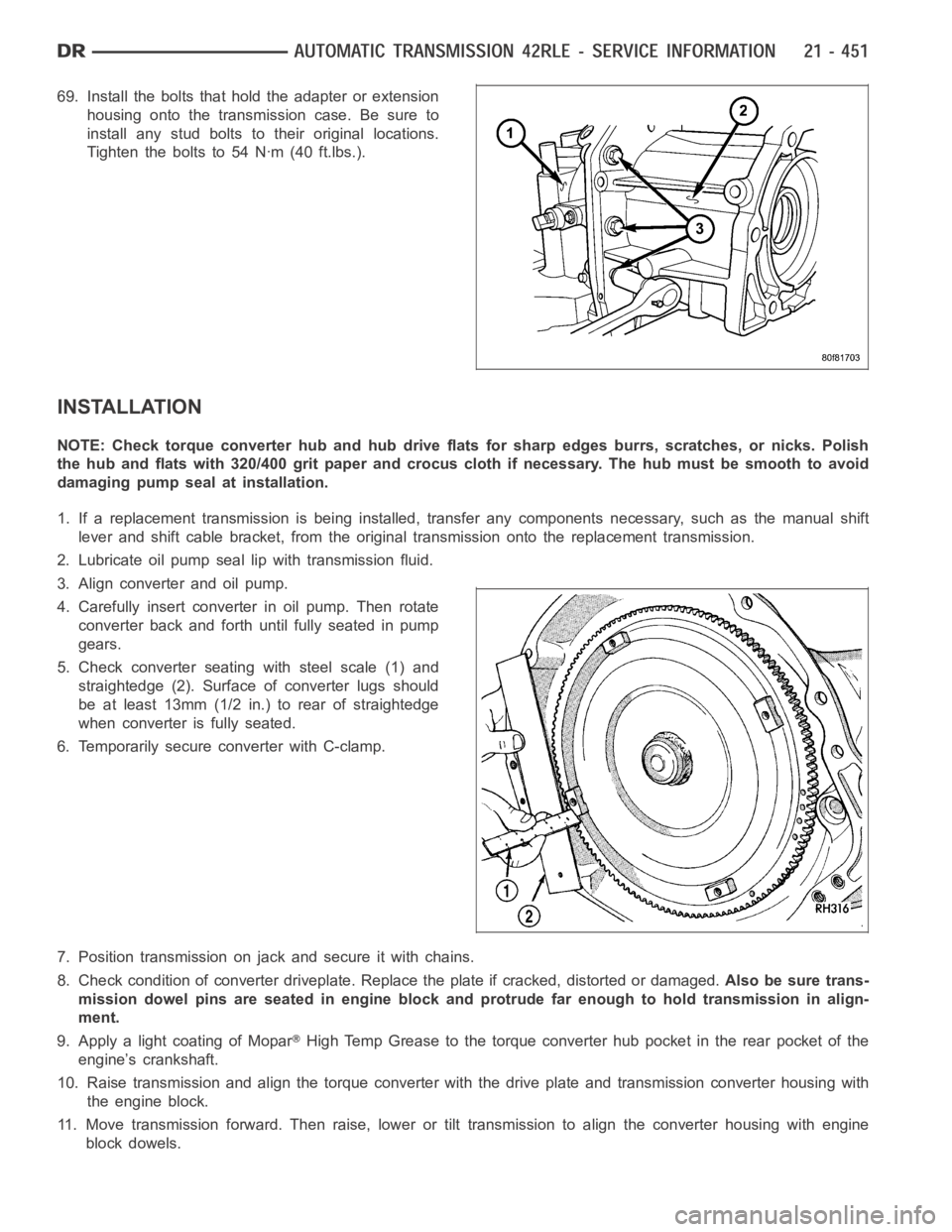
69. Install the bolts that hold the adapter or extension
housing onto the transmission case. Be sure to
install any stud bolts to their original locations.
Tighten the bolts to 54 Nꞏm (40 ft.lbs.).
INSTALLATION
NOTE: Check torque converter hub and hub drive flats for sharp edges burrs,scratches, or nicks. Polish
the hub and flats with 320/400 grit paper and crocus cloth if necessary. Thehub must be smooth to avoid
damaging pump seal at installation.
1. If a replacement transmission is being installed, transfer any components necessary, such as the manual shift
lever and shift cable bracket, from the original transmission onto the replacement transmission.
2. Lubricate oil pump seal lip with transmission fluid.
3. Align converter and oil pump.
4. Carefully insert converter in oil pump. Then rotate
converter back and forth until fully seated in pump
gears.
5. Check converter seating with steel scale (1) and
straightedge (2). Surface of converter lugs should
be at least 13mm (1/2 in.) to rear of straightedge
when converter is fully seated.
6. Temporarily secure converter with C-clamp.
7. Position transmission on jack and secure it with chains.
8. Check condition of converter driveplate. Replace the plate if cracked,distorted or damaged.Also be sure trans-
mission dowel pins are seated in engine block and protrude far enough to holdtransmissioninalign-
ment.
9. Apply a light coating of Mopar
High Temp Grease to the torque converter hub pocket in the rear pocket of the
engine’s crankshaft.
10. Raise transmission and align the torque converter with the drive plateand transmission converter housing with
the engine block.
11. Move transmission forward. Then raise, lower or tilt transmission to align the converter housing with engine
block dowels.
Page 3000 of 5267
SPECIFICATIONS
42RLE AUTOMATIC TRANSMISSION
GENERAL SPECIFICATIONS
Transmission TypeFour-Speed Automatic, Electronically Controlled, Fully
Adaptive, Electronically Modulated Torque Converter
Lubrication Method Pump (internal - external gear-type)
Cooling Method Water Heat Exchanger and/or Air-to-Oil Heat Exchanger
GEAR RATIOS
1st Gear 2.84:1
2nd Gear 1.57:1
3rd Gear (Direct) 1.00:1
4th Gear (Overdrive) 0.69:1
Reverse Gear 2.21:1
BEARING PRELOAD (Drag Torque)
Description Metric Standard
Output Shaft 0.22-0.903 Nꞏm 1-8 in. lbs.
CLUTCH PACK
Description Metric Standard
Low/Reverse Clutch (Select
Reaction Plate)0.84-1.60 mm 0.033-0.063 in.
Two/Four Clutch (No Select) 0.76-2.64 mm 0.030-0.104 in.
Reverse Clutch (Select Snap Ring) 0.89-1.37 mm 0.035-0.054 in.
Overdrive Clutch (No Select) 1.07-3.25 mm 0.042-0.128 in.
Underdrive Clutch (Select Reaction
Plate)0.94-1.50 mm 0.037-0.059 in.
INPUT SHAFT
Description Metric Standard
End Play 0.127-0.635 mm 0.005-0.025 in.
OIL PUMP CLEARANCES
DESCRIPTION METRIC STANDARD
Outer Gear-to-Crescent 0.060-0.298 mm 0.0023-0.0117 in.
Inner Gear-to-Crescent 0.093-0.385 mm 0.0036-0.0151 in.
Outer Gear-to-Pocket 0.089-0.202 mm 0.0035-0.0079 in.
Outer Gear Side Clearance 0.020-0.046 mm 0.0008-0.0018 in.
Inner Gear Side Clearance 0.020-0.046 mm 0.0008-0.0018 in.
Page 3001 of 5267
TORQUE SPECIFICATIONS
Description Nꞏm Ft. Lbs. In. Lbs.
Bolt, Torque Converter Housing to Engine 68 50 -
Bolt, Converter-to-Driveplate 88 65 -
Bolt, Fluid Filter-to-Valve Body 5 - 45
Bolt, L/R Piston Retainer-to-Case 5 - 45
Bolt, Adapter/Extension Housing 54 40 -
Bolt, Manual Valve Lever-to-Manual Valve 5 - 45
Bolt, Oil Pan-to-Case 20 14.5 -
Bolt, Oil Pump-to-Case 30 - 265
Bolt, Park Sprag Retainer 4.5 - 40
Bolt, Reaction Shaft Support Halves 28 - 250
Bolt, Solenoid/Pressure Switch Assembly-to-
Valve Body5.5 - 50
Bolt, Valve Body-to-Case 12 - 105
Bolt, Valve Body-to-Transfer Plate 5 - 45
Fitting, Cooler Line 47.5 35 -
Nut, Output Shaft 271 200 -
Plug, Pressure Tap 5 - 45
Bolt, Input Speed-to-Case Sensor 9 - 80
Bolt, Output Speed-to-Case Sensor 9 - 80
Nut, Transfer Case 47 35 -
Bolt, Crossmember to Frame 68 50 -
Bolt, Rear Support to Transmission 47 35 -
Bolt, Clevis Bracket to Crossmember 47 35 -
Bolt, Clevis Bracket to Transmission 68 50 -
Screw, TRS/Manual Shaft Retaining 5 - 45
Screw, 2/4 Accumulator Retainer Plate 5 - 45
Page 3014 of 5267
FLUID AND FILTER
DIAGNOSIS AND TESTING
CAUSES OF BURNT FLUID
Burnt, discolored fluid is a result of overheating which has two primary causes.
1. A result of restricted fluid flow through the main and/or auxiliary cooler. This condition is usually the result of a
faulty or improperly installed drainback valve, a damaged oil cooler, or severe restrictions in the coolers and lines
caused by debris or kinked lines.
2. Heavy duty operation with a vehicle not properly equipped for this type of operation. Trailer towing or similar high
load operation will overheat the transmission fluid if the vehicle is improperly equipped. Such vehicles should
have an auxiliary transmission fluid cooler, a heavy duty cooling system,and the engine/axle ratio combination
needed to handle heavy loads.
EFFECTS OF INCORRECT FLUID LEVEL
Alowfluidlevelallowsthepumptotakeinairalongwiththefluid.Airinthe fluid will cause fluid pressures to be
low and develop slower than normal. If the transmission is overfilled, thegears churn the fluid into foam. This aer-
ates the fluid and causing the same conditions occurring with a low level. In either case, air bubbles cause fluid
overheating, oxidation, and varnish buildup which interferes with valveand clutch operation. Foaming also causes
fluid expansion which can result in fluid overflow from the transmission vent or fill tube. Fluid overflow can easily be
mistaken for a leak if inspection is not careful.
FLUID CONTAMINATION
Transmission fluid contamination is generally a result of:
adding incorrect fluid
failure to clean dipstick and fill tube when checking level
engine coolant entering the fluid
internal failure that generates debris
overheat that generates sludge (fluid breakdown)
failure to replace contaminated converter after repair
The use of non-recommended fluids can result in transmission failure. Theusual results are erratic shifts, slippage,
abnormal wear and eventual failure due to fluid breakdown and sludge formation. Avoid this condition by using rec-
ommended fluids only.
The dipstick cap and fill tube should be wiped clean before checking fluid level. Dirt, grease and other foreign mate-
rial on the cap and tube could fall into the tube if not removed beforehand. Take the time to wipe the cap and tube
clean before withdrawing the dipstick.
Engine coolant in the transmission fluid is generally caused by a cooler malfunction. The only remedy is to replace
the radiator as the cooler in the radiator is not a serviceable part. If coolant has circulated through the transmission,
an overhaul is necessary.
The torque converter should also be replaced whenever a failure generatessludge and debris. This is necessary
because normal converter flushing procedures will not remove all contaminants.
STANDARD PROCEDURE
FLUID LEVEL CHECK
The transmission sump has a dipstick to check oil similar to most automatictransmissions. It is located on the left
side of the engine. Be sure to wipe all dirt from dipstick handle before removing.
The torque converter fills in both the PARK and NEUTRAL positions. Place the selector lever in PARK to be sure
that the fluid level check is accurate.The engine should be running at idle speed for at least one minute, with
the vehicle on level ground.At normal operating temperature (approximately 82° C or 180° F), the fluidlevel is
correct if it is in the HOT region (cross-hatched area) on the oil level indicator. The fluid level should be in COLD
region at 21° C (70° F) fluid temperature. Adjust fluid level as necessary.Use only Mopar
ATF+4, Automatic Trans-
mission Fluid.
Page 3015 of 5267
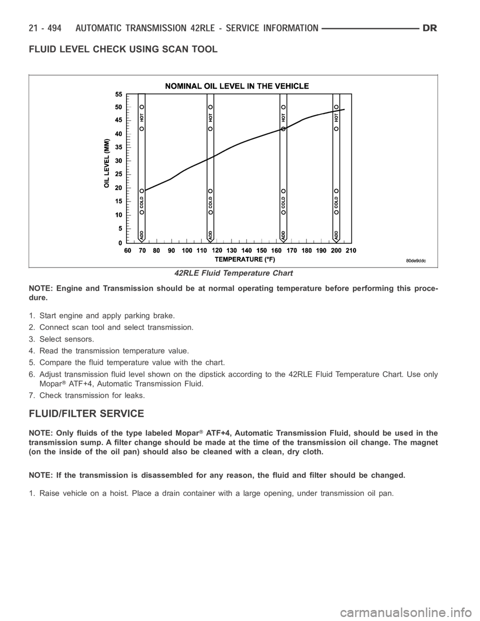
FLUID LEVEL CHECK USING SCAN TOOL
NOTE: Engine and Transmission should be at normal operating temperature before performing this proce-
dure.
1. Start engine and apply parking brake.
2. Connect scan tool and select transmission.
3. Select sensors.
4. Read the transmission temperature value.
5. Compare the fluid temperature value with the chart.
6. Adjust transmission fluid level shown on the dipstick according to the 42RLE Fluid Temperature Chart. Use only
Mopar
ATF+4, Automatic Transmission Fluid.
7. Check transmission for leaks.
FLUID/FILTER SERVICE
NOTE: Only fluids of the type labeled MoparATF+4, Automatic Transmission Fluid, should be used in the
transmission sump. A filter change should be made at the time of the transmission oil change. The magnet
(on the inside of the oil pan) should also be cleaned with a clean, dry cloth.
NOTE: If the transmission is disassembled for any reason, the fluid and filter should be changed.
1. Raise vehicle on a hoist. Place a drain container with a large opening, under transmission oil pan.
42RLE Fluid Temperature Chart
Page 3016 of 5267
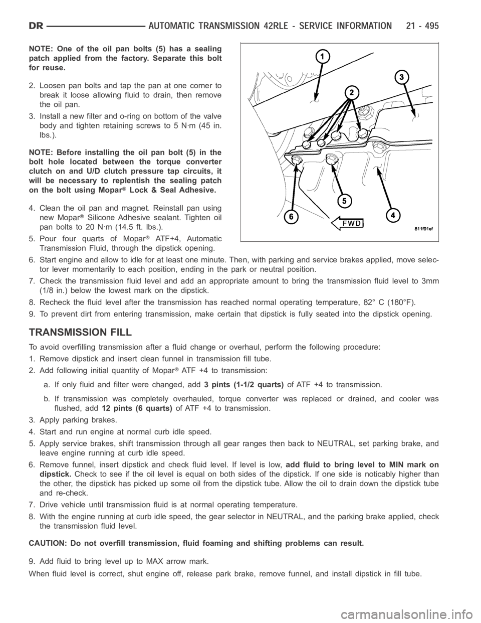
NOTE: One of the oil pan bolts (5) has a sealing
patch applied from the factory. Separate this bolt
for reuse.
2. Loosen pan bolts and tap the pan at one corner to
break it loose allowing fluid to drain, then remove
the oil pan.
3. Install a new filter and o-ring on bottom of the valve
body and tighten retaining screws to 5 Nꞏm (45 in.
lbs.).
NOTE: Before installing the oil pan bolt (5) in the
bolt hole located between the torque converter
clutch on and U/D clutch pressure tap circuits, it
will be necessary to replentish the sealing patch
on the bolt using Mopar
Lock & Seal Adhesive.
4. Clean the oil pan and magnet. Reinstall pan using
new Mopar
Silicone Adhesive sealant. Tighten oil
pan bolts to 20 Nꞏm (14.5 ft. lbs.).
5. Pour four quarts of Mopar
AT F + 4 , A u t o m a t i c
Transmission Fluid, through the dipstick opening.
6. Start engine and allow to idle for at least one minute. Then, with parkingand service brakes applied, move selec-
tor lever momentarily to each position, ending in the park or neutral position.
7. Check the transmission fluid level and add an appropriate amount to bring the transmission fluid level to 3mm
(1/8 in.) below the lowest mark on the dipstick.
8. Recheck the fluid level after the transmission has reached normal operating temperature, 82° C (180°F).
9. To prevent dirt from entering transmission, make certain that dipstickis fully seated into the dipstick opening.
TRANSMISSION FILL
To avoid overfilling transmission after a fluid change or overhaul, perform the following procedure:
1. Remove dipstick and insert clean funnel in transmission fill tube.
2. Add following initial quantity of Mopar
ATF+4totransmission:
a. If only fluid and filter were changed, add3 pints (1-1/2 quarts)of ATF +4 to transmission.
b. If transmission was completely overhauled, torque converter was replaced or drained, and cooler was
flushed, add12 pints (6 quarts)of ATF +4 to transmission.
3. Apply parking brakes.
4. Start and run engine at normal curb idle speed.
5. Apply service brakes, shift transmission through all gear ranges then back to NEUTRAL, set parking brake, and
leave engine running at curb idle speed.
6. Remove funnel, insert dipstick andcheck fluid level. If level is low,add fluid to bring level to MIN mark on
dipstick.Check to see if the oil level is equal on both sides of the dipstick. If one side is noticably higher than
the other, the dipstick has picked up some oil from the dipstick tube. Allowthe oil to drain down the dipstick tube
and re-check.
7. Drive vehicle until transmission fluid is at normal operating temperature.
8. With the engine running at curb idle speed, the gear selector in NEUTRAL,and the parking brake applied, check
the transmission fluid level.
CAUTION: Do not overfill transmission, fluid foaming and shifting problems can result.
9. Add fluid to bring level up to MAX arrow mark.
When fluid level is correct, shut engine off, release park brake, remove funnel, and install dipstick in fill tube.
Page 3044 of 5267
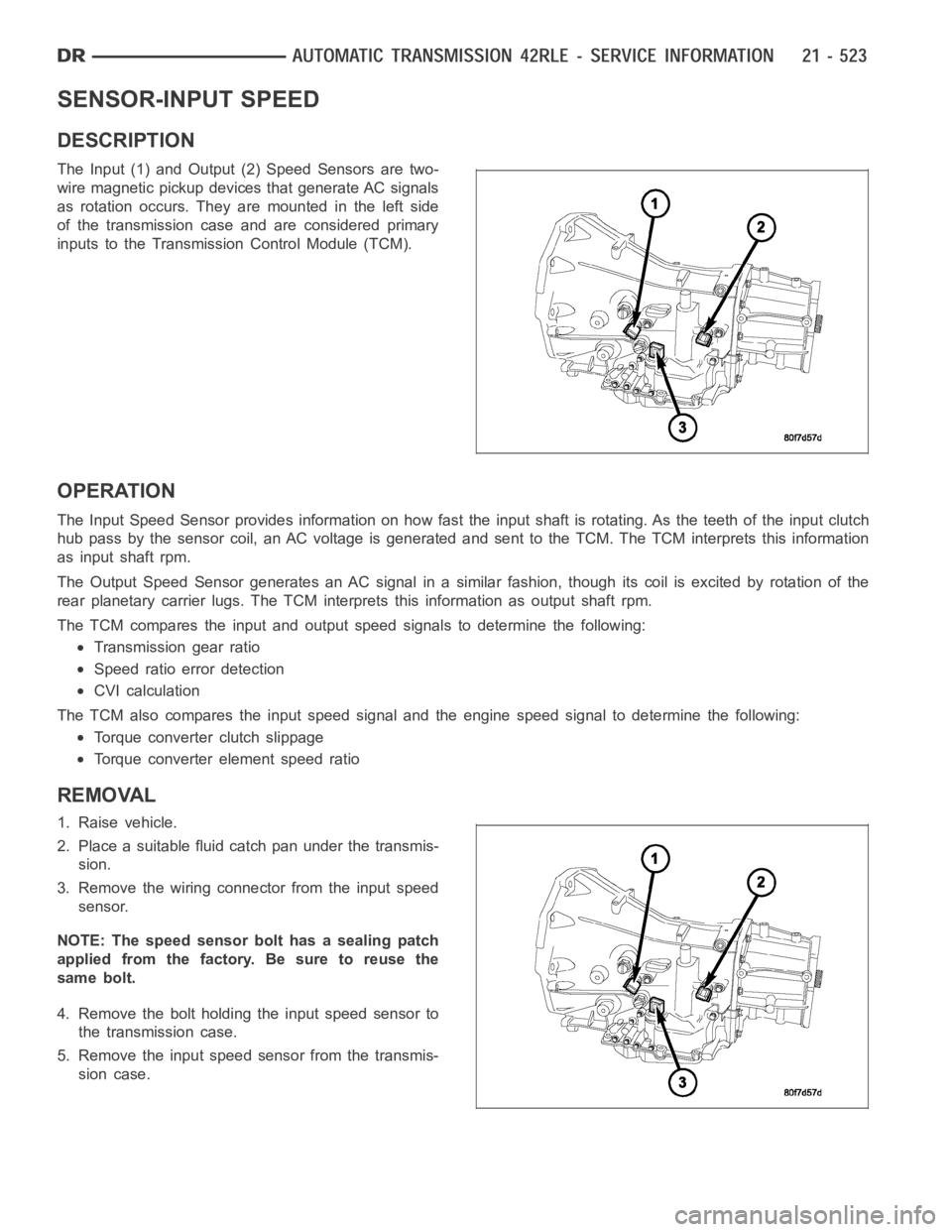
SENSOR-INPUT SPEED
DESCRIPTION
The Input (1) and Output (2) Speed Sensors are two-
wire magnetic pickup devices that generate AC signals
as rotation occurs. They are mounted in the left side
of the transmission case and are considered primary
inputs to the Transmission Control Module (TCM).
OPERATION
The Input Speed Sensor provides information on how fast the input shaft is rotating. As the teeth of the input clutch
hub pass by the sensor coil, an AC voltage is generated and sent to the TCM. The TCM interprets this information
as input shaft rpm.
The Output Speed Sensor generates an AC signal in a similar fashion, thoughitscoilisexcitedbyrotationofthe
rear planetary carrier lugs. The TCM interprets this information as outputshaftrpm.
The TCM compares the input and output speed signals to determine the following:
Transmission gear ratio
Speed ratio error detection
CVI calculation
The TCM also compares the input speed signal and the engine speed signal to determine the following:
Torque converter clutch slippage
Torque converter element speed ratio
REMOVAL
1. Raise vehicle.
2. Place a suitable fluid catch pan under the transmis-
sion.
3. Remove the wiring connector from the input speed
sensor.
NOTE: The speed sensor bolt has a sealing patch
applied from the factory. Be sure to reuse the
same bolt.
4. Remove the bolt holding the input speed sensor to
the transmission case.
5. Remove the input speed sensor from the transmis-
sion case.
Page 3046 of 5267
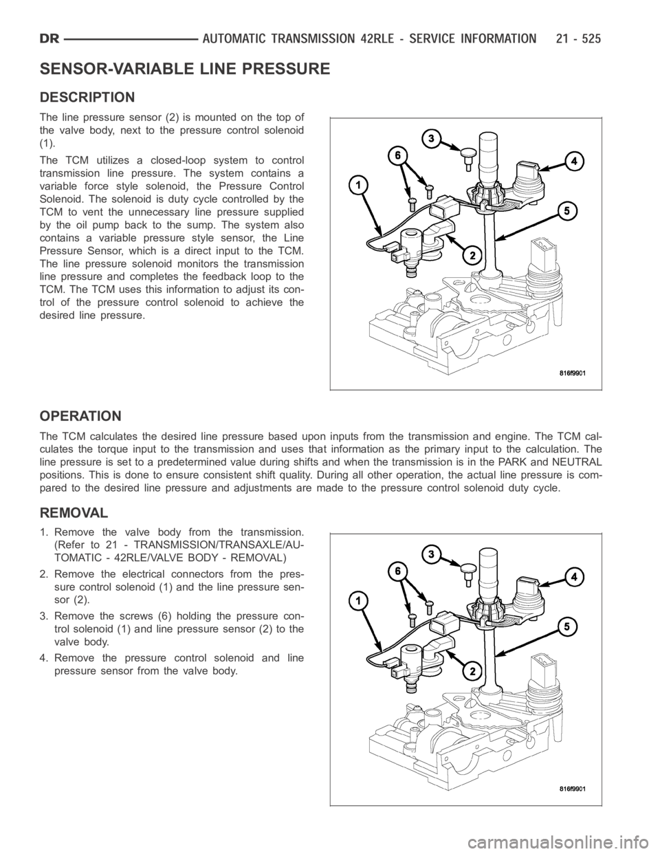
SENSOR-VARIABLE LINE PRESSURE
DESCRIPTION
The line pressure sensor (2) is mounted on the top of
the valve body, next to the pressure control solenoid
(1).
The TCM utilizes a closed-loop system to control
transmission line pressure. The system contains a
variable force style solenoid, the Pressure Control
Solenoid. The solenoid is duty cycle controlled by the
TCM to vent the unnecessary line pressure supplied
by the oil pump back to the sump. The system also
contains a variable pressure style sensor, the Line
Pressure Sensor, which is a direct input to the TCM.
The line pressure solenoid monitors the transmission
line pressure and completes the feedback loop to the
TCM. The TCM uses this information to adjust its con-
trol of the pressure control solenoid to achieve the
desired line pressure.
OPERATION
The TCM calculates the desired line pressure based upon inputs from the transmission and engine. The TCM cal-
culates the torque input to the transmission and uses that information as the primary input to the calculation. The
line pressure is set to a predetermined value during shifts and when the transmission is in the PARK and NEUTRAL
positions. This is done to ensure consistent shift quality. During all other operation, the actual line pressure is com-
pared to the desired line pressure and adjustments are made to the pressurecontrol solenoid duty cycle.
REMOVAL
1. Remove the valve body from the transmission.
(Refer to 21 - TRANSMISSION/TRANSAXLE/AU-
TOMATIC - 42RLE/VALVE BODY - REMOVAL)
2. Remove the electrical connectors from the pres-
sure control solenoid (1) and the line pressure sen-
sor (2).
3. Remove the screws (6) holding the pressure con-
trol solenoid (1) and line pressure sensor (2) to the
valve body.
4. Remove the pressure control solenoid and line
pressure sensor from the valve body.