Page 3070 of 5267
4. Separate the torque converter from the transmission.
INSTALLATION
NOTE: Check converter hub and drive notches for sharp edges, burrs, scratches, or nicks. Polish the hub
and notches with 320/400 grit paper or crocus cloth if necessary. The hub must be smooth to avoid dam-
aging the pump seal at installation.
1. Lubricate oil pump seal lip with transmission fluid.
2. Place torque converter in position on transmission.
CAUTION: Do not damage oil pump seal or bush-
ing while inserting torqueconverterintothefront
of the transmission.
3. Align torque converter to oil pump seal opening.
4. Insert torque converter hub into oil pump.
5. While pushing torque converter inward, rotate con-
verter until converter is fully seated in the oil pump
gears.
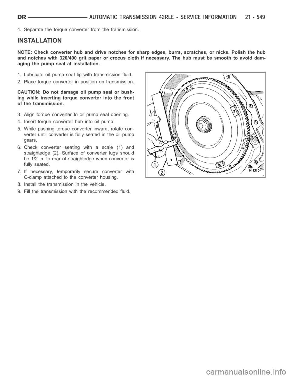
6. Check converter seating with a scale (1) and
straightedge (2). Surface of converter lugs should
be 1/2 in. to rear of straightedge when converter is
fully seated.
7. If necessary, temporarily secure converter with
C-clamp attached to the converter housing.
8. Install the transmission in the vehicle.
9. Fill the transmission with the recommended fluid.
Page 3077 of 5267
SENSOR-TRANSMISSION TEMPERATURE
DESCRIPTION
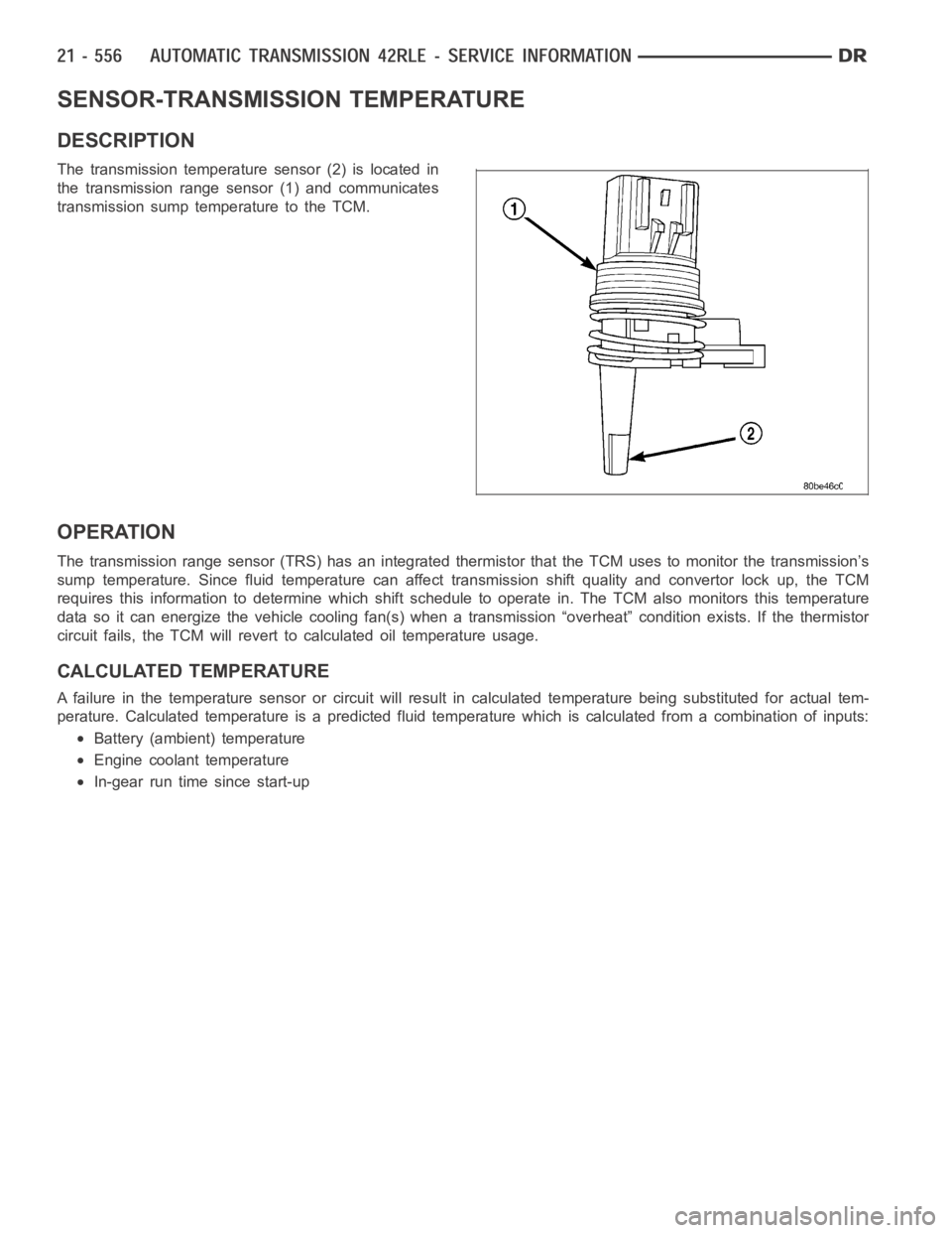
The transmission temperature sensor (2) is located in
the transmission range sensor (1) and communicates
transmission sump temperature to the TCM.
OPERATION
The transmission range sensor (TRS) has an integrated thermistor that theTCM uses to monitor the transmission’s
sump temperature. Since fluid temperature can affect transmission shiftquality and convertor lock up, the TCM
requires this information to determine which shift schedule to operate in. The TCM also monitors this temperature
data so it can energize the vehicle cooling fan(s) when a transmission “overheat” condition exists. If the thermistor
circuit fails, the TCM will revert to calculated oil temperature usage.
CALCULATED TEMPERATURE
A failure in the temperature sensor or circuit will result in calculated temperature being substituted for actual tem-
perature. Calculated temperature is a predicted fluid temperature whichis calculated from a combination of inputs:
Battery (ambient) temperature
Engine coolant temperature
In-gear run time since start-up
Page 3080 of 5267
THERMAL VALVE
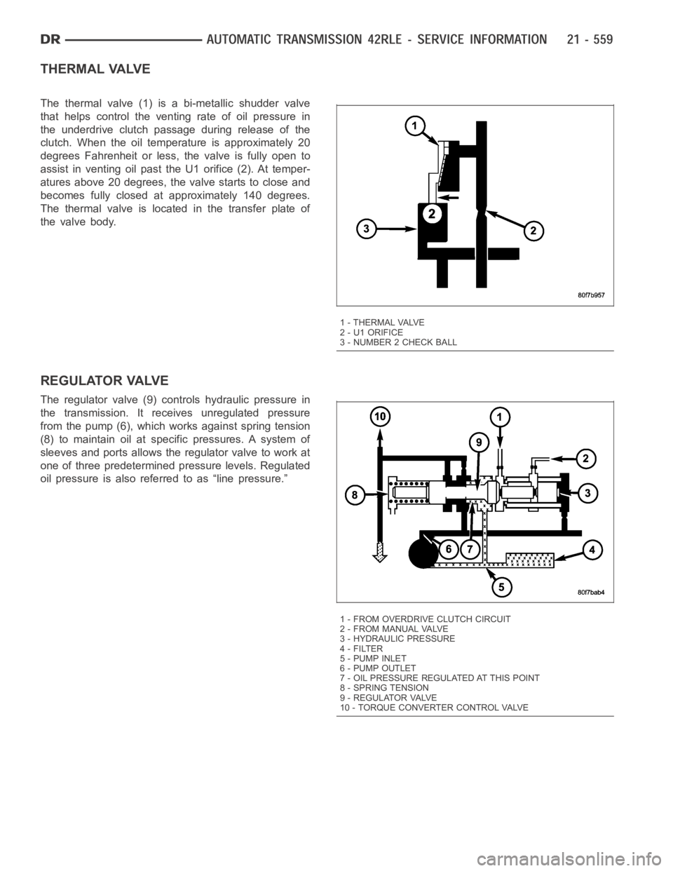
The thermal valve (1) is a bi-metallic shudder valve
that helps control the venting rate of oil pressure in
the underdrive clutch passage during release of the
clutch. When the oil temperature is approximately 20
degrees Fahrenheit or less, the valve is fully open to
assist in venting oil past the U1 orifice (2). At temper-
atures above 20 degrees, the valve starts to close and
becomes fully closed at approximately 140 degrees.
The thermal valve is located in the transfer plate of
the valve body.
REGULATOR VALVE
The regulator valve (9) controls hydraulic pressure in
the transmission. It receives unregulated pressure
from the pump (6), which works against spring tension
(8) to maintain oil at specific pressures. A system of
sleeves and ports allows the regulator valve to work at
one of three predetermined pressure levels. Regulated
oil pressure is also referred to as “line pressure.”
1 - THERMAL VALVE
2 - U1 ORIFICE
3 - NUMBER 2 CHECK BALL
1 - FROM OVERDRIVE CLUTCH CIRCUIT
2 - FROM MANUAL VALVE
3 - HYDRAULIC PRESSURE
4-FILTER
5-PUMPINLET
6 - PUMP OUTLET
7 - OIL PRESSURE REGULATED AT THIS POINT
8 - SPRING TENSION
9 - REGULATOR VALVE
10 - TORQUE CONVERTER CONTROL VALVE
Page 3084 of 5267
1. Disconnect the transmission range sensor (5) and
solenoid/pressure switchassembly wiring connec-
tors.
2. Disconnect the variable line pressure connector (4),
if equipped.
3. Disconnect the shift cable from the shift lever (at
the transmission).
4. Move the manual shift lever clockwise as far as it
will go. This should be one position past the L posi-
tion. Then remove the manual shift lever.
NOTE: One of the oil pan bolts has a sealing patch
applied from the factory. Separate this bolts for
reuse.
5. Remove transmission pan bolts (2).
6. Remove transmission oil pan (1).
Page 3085 of 5267
7. Remove oil filter (1) from valve body. It is held in
place by two screws.
8. Remove valve body bolts-to-case (1).
CAUTION: The overdrive and underdrive accumu-
lators and springs may fall out when removing the
valve body.
9. Carefully remove valve body assembly (1) from the
transmission.
DISASSEMBLY
NOTE: If the valve body is being reconditioned or replaced, it is necessaryto perform the Quick Learn Pro-
cedure using the scan tool (Refer to 8 - ELECTRICAL/ELECTRONIC CONTROL MODULES/TRANSMISSION
CONTROL MODULE - STANDARD PROCEDURE)
Page 3099 of 5267
18. Install the variable line pressure header onto the
manual shaft (5).
19. Install the shoulder screw (3) to hold the variable
line pressure header (4) to the valve body.
20. Install the pressure control solenoid and line pres-
sure sensor into the valve body.
21. Install the screws (6) to hold the pressure control
solenoid (1) and line pressure sensor (2) to the
valve body.
22. Install the electrical connectors to the pressure
control solenoid (1) and the line pressure sensor
(2).
INSTALLATION
1. Install valve body into position and start bolts (1).
Torque valve body to transmission case bolts (1) to
12 Nꞏm (105 in. lbs.) torque.
2. Install transmission oil filter (1).
Page 3100 of 5267
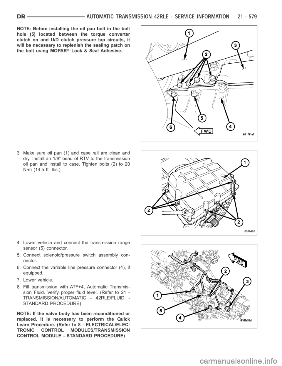
NOTE: Before installing the oil pan bolt in the bolt
hole (5) located between the torque converter
clutch on and U/D clutch pressure tap circuits, it
will be necessary to replenish the sealing patch on
the bolt using MOPAR
Lock & Seal Adhesive.
3. Make sure oil pan (1) and case rail are clean and
dry. Install an 1/8” bead of RTV to the transmission
oil pan and install to case. Tighten bolts (2) to 20
Nꞏm (14.5 ft. lbs.).
4. Lower vehicle and connect the transmission range
sensor (5) connector.
5. Connect solenoid/pressure switch assembly con-
nector.
6. Connect the variable line pressure connector (4), if
equipped.
7. Lower vehicle.
8. Fill transmission with ATF+4, Automatic Transmis-
sion Fluid. Verify proper fluid level. (Refer to 21 -
TRANSMISSION/AUTOMATIC - 42RLE/FLUID -
STANDARD PROCEDURE)
NOTE: If the valve body has been reconditioned or
replaced, it is necessary to perform the Quick
Learn Procedure. (Refer to 8 - ELECTRICAL/ELEC-
TRONIC CONTROL MODULES/TRANSMISSION
CONTROL MODULE - STANDARD PROCEDURE)
Page 3109 of 5267
P0218-HIGH TEMPERATURE OPERATION ACTIVATED
For a complete wiring diagramRefer to Section 8W.
Theory of Operation
The DTC is intended as an informational DTC to aid the technician in determining the root cause of a customer
dirveability issue. The DTC is also intended to alert the technician to determine if a cooling system malfunction has
occurred or if an additional transmission air to oil cooler is needed to support the customers driving behavior.
When Monitored:
Whenever the engine is running.
Set Condition:
Immediately after a Overheat shift schedule is activated when the Transmission temperature exceeds 127° C
or 260° F.
Possible Causes
H I G H T E M P E R AT U R E O P E R AT I O N A C T I VAT E D
TORQUE CONVERTER CLUTCH SLIPPING / NOT ACTIVATING
EXCESSIVE TIME IDLING IN GEAR
Always perform the Pre-Diagnostic Troubleshooting procedure before proceeding. (Refer to 21 - TRANSMIS-
SION/TRANSAXLE/AUTOMATIC - 45RFE/545RFE - STANDARD PROCEDURE)
Diagnostic Test
1.HIGH TEMPERATURE OPERATION
This DTC is an informational DTC designed to aid the Technician in diagnosing shift quality complaints.
This DTC indicates that the transmission has been operating in the
Overheatshift schedule which may generate
a customer complaint.
The customer driving patterns may indicate the need for an additional transmission oil cooler.
Verify proper Engine cooling system operation which would affect proper transmission operation.
Verify proper torque converter clutch operation.
With the scan tool, check the DTC EVENT DATA to help identify the conditionsin which the DTC was set.
If there are no possible causes remaining, view repair.
Repair
Repair the cause of transmission overheating. Refer to the Service Information for the proper repair
procedure. Make sure to check for any Service Bulletins pertaining to thisproblem.
Perform 45RFE/545RFE TRANSMISSION VERIFICATION TEST - VER 1. (Refer to 21- TRANSMIS-
SION/TRANSAXLE/AUTOMATIC - 45RFE/545RFE - STANDARD PROCEDURE)