Page 1155 of 2893

to the front subframe by looping the strap (A) over
the front of the front subframe, then se")
����
��������
����
14-239
VSB02C000016
A
B
C
ABC
D
E
F
33. Attach the front subframe adapter (VSB02C000016)
to the front subframe by looping the strap (A) over
the front of the front subframe, then secure the
strap with the stop (B), then tighten the wing nut (C).
34. Raise a jack and line up the slots in the arms with the bolt holes on the corner of the jack base, then
tighten the bolts.
35. Remove the four bolts securing the front subframe, and lower the front subframe.
36. Secure the steering gearbox to the body with a rope. 37. Remove the driveshafts from the differential and
the intermediate shaft. Coat all precision machined
surfaces with clean engine oil, then put plastic bags
over the driveshaft ends.
38. Remove the three bolts securing the shift cable holder (A), then remove the shift cable cover (B).
39. Pry up the lock tab of the lock washer (C), and remove the lock bolt (D) and the lock washer, then
separate the shift cable (E) from the selector control
shaft (F). Do not bend the shift cable excessively.
(cont’d)
08/08/21 14:48:40 61SNR030_140_0241
ProCarManuals.com
DYNOMITE -2009-
Page 1161 of 2893
 A
6x1.0mm
12 N·m
(1.2 kgf·m, 8.7 lbf·ft)
6x1.0mm
12 N·m
(1.2 kgf·m, 8.7 lbf·ft)6x1.0mm
9.8 N·m
(1.0 kgf·m,
7.2 lbf·ft)
D
6x1.0")
�����
��
�
�
14-245
B
6x1.0mm
12 N·m
(1.2 kgf·m, 8.7 lbf·ft) A
6x1.0mm
12 N·m
(1.2 kgf·m, 8.7 lbf·ft)
6x1.0mm
12 N·m
(1.2 kgf·m, 8.7 lbf·ft)6x1.0mm
9.8 N·m
(1.0 kgf·m,
7.2 lbf·ft)
D
6x1.0mm
14 N·m
(1.4 kgf·m,
10 lbf·ft)A
B
C
E
F
VSB02C000016
A
B
C
17. Attach the torque converter to the drive plate with the eight bolts (A). Rotate the crankshaft pulley as
necessary to tighten the bolts to 1/2 of the specified
torque, then to the final torque, in a crisscross
pattern. After tightening the last bolt, check that the
crankshaft rotate freely.
18. Install the torque converter cover (B). 19. Install the control lever (A) over the selector control
shaft (B).
20. Secure the control lever with a new lock washer (C) and the lock bolt (D), then bend the lock tab of the
lock washer against the bolt head.
21. Install the shift cable cover (E), and install the shift cable holder (F) on the shift cable cover.
22. Set the front subframe adapter (VSB02C000016) to the front subframe by looping the strap (A) over the
front of the front subframe, then secure the strap
with the stop (B), then tighten the wing nut (C).
(cont’d)
08/08/21 14:48:45 61SNR030_140_0247
ProCarManuals.com
DYNOMITE -2009-
Page 1170 of 2893
���
��������
����
�(�#�'�������
���
�����
�
���
��������� �����)����
14-254 Automatic Transmission
Shift Lever Removal
A
A
B C
A
B
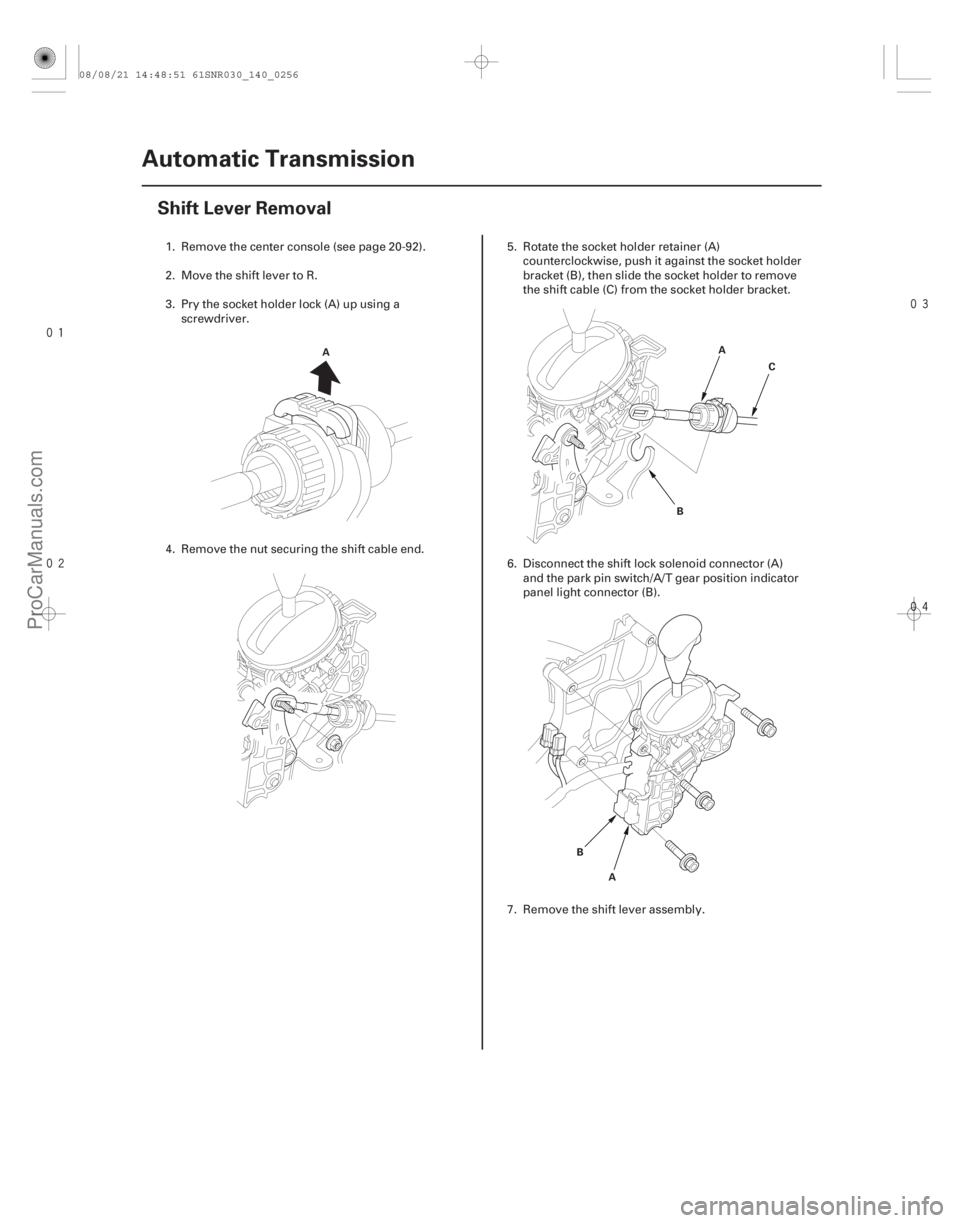
1. Remove the center console (see page 20-92).
2. Move the shift lever to R.
3. Pry the socket holder lock (A) up using a
screwdriver.
4. Remove the nut securing the shift cable end. 5. Rotate the socket holder retainer (A)
counterclockwise, push it against the socket holder
bracket (B), then slide the socket holder to remove
the shift cable (C) from the socket holder bracket.
6. Disconnect the shift lock solenoid connector (A) and the park pin switch/A/T gear position indicator
panel light connector (B).
7. Remove the shift lever assembly.
08/08/21 14:48:51 61SNR030_140_0256
ProCarManuals.com
DYNOMITE -2009-
Page 1171 of 2893
����
�(�#�'�������
���
�����
�
���
��������� �����)����
14-255
Shift Lever Installation
B
C
8x1.25mm
22 N·m
(2.2 kgf·m, 16 lbf·ft)A
1. Install the shift lever assembly (A).
2. Connect the shift lock solenoid connector (B) and
the park pin switch/A/T gear position indicator
panel light connector (C).
3. Install the shift cable on the shift lever, and adjust the cable (see step 5 on page 14-259).
08/08/21 14:48:51 61SNR030_140_0257
ProCarManuals.com
DYNOMITE -2009-
Page 1172 of 2893
����
�(�#�'�������
���
�����
�
���
���������"�����)�
��
14-256Automatic Transmission
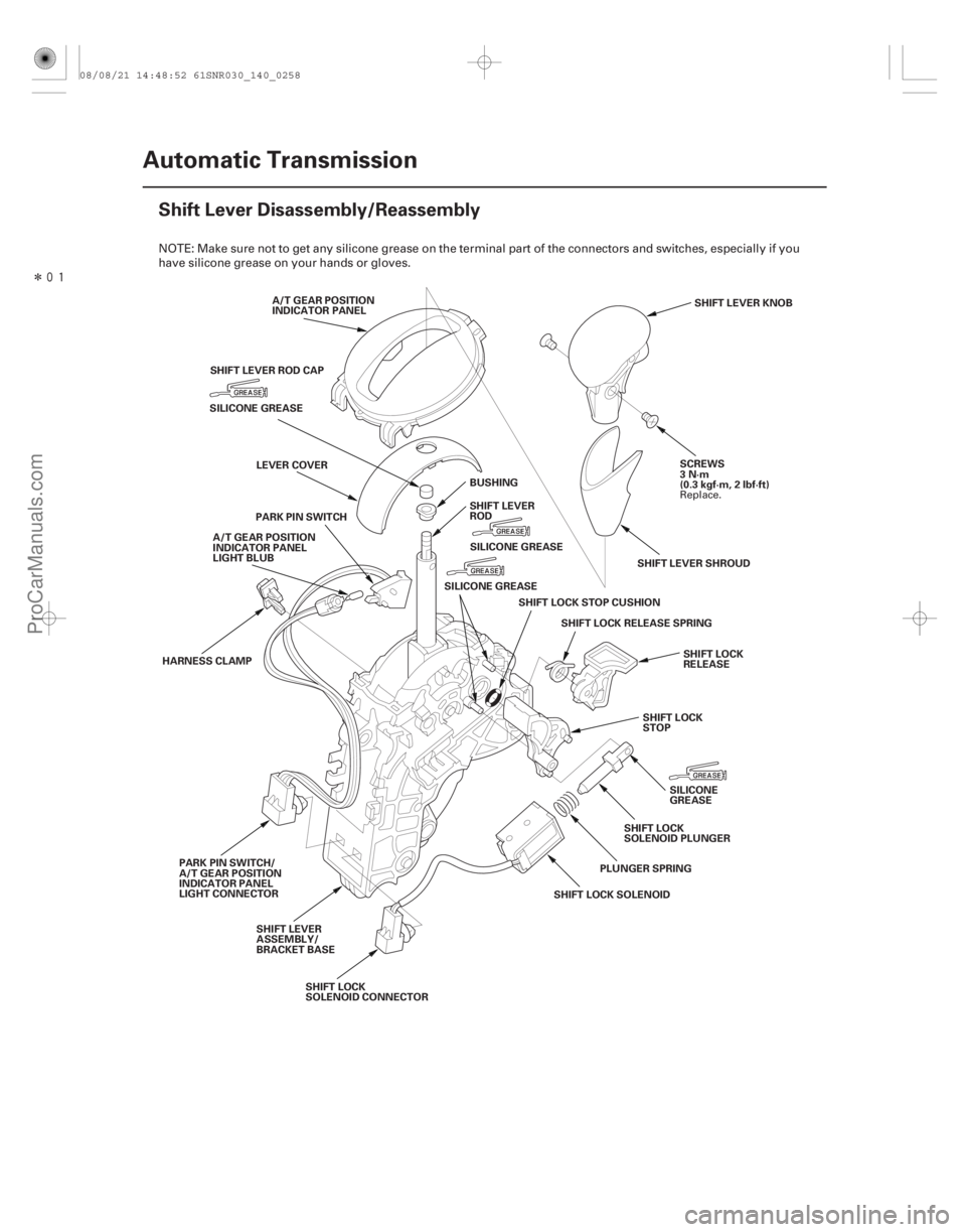
Shift Lever Disassembly/Reassembly
A/T GEAR POSITION
INDICATOR PANEL
SCREWS
3N·m
(0.3 kgf·m, 2 lbf·ft)SHIFT LEVER KNOB
SILICONE GREASE
SHIFT LOCK SOLENOID
HARNESS CLAMP
PARK PIN SWITCH/
A/T GEAR POSITION
INDICATOR PANEL
LIGHT CONNECTOR PARK PIN SWITCH
SHIFT LOCK RELEASE SPRING
SHIFT LOCK
SOLENOID PLUNGER
SHIFTLOCKSTOPCUSHION
SHIFT LOCK
STOP
SHIFT LEVER
ASSEMBLY/
BRACKET BASE SHIFT LEVER
ROD
LEVER COVER
A/T GEAR POSITION
INDICATOR PANEL
LIGHT BLUB
SHIFT LOCK
RELEASE
SHIFT LEVER SHROUD
PLUNGER SPRING SILICONE
GREASE
SHIFT LOCK
SOLENOID CONNECTOR BUSHING
SHIFT LEVER ROD CAP
SILICONE GREASESILICONE GREASE
NOTE: Make sure not to get any silicone grease on the terminal part of the connectors and switches, especially if you
have silicone grease on your hands or gloves.
Replace.
08/08/21 14:48:52 61SNR030_140_0258
ProCarManuals.com
DYNOMITE -2009-
Page 1173 of 2893
����
14-257
Shift Cable Replacement
A A
B C
A BC
D
E
F
1. Raise the vehicle on a lift, or apply the parking
brake, block the rear wheel")
���
��������
����
�(�#�'�������
���
�����
�
���
�������
� �����)����
14-257
Shift Cable Replacement
A A
B C
A BC
D
E
F
1. Raise the vehicle on a lift, or apply the parking
brake, block the rear wheels, and raise the front of
the vehicle. Make sure it is securely supported.
2. Move the shift lever to R.
3. Remove the center console (see page 20-92).
4. Pry the socket holder lock (A) up using a screwdriver.
5. Remove the nut securing the shift cable end. 6. Rotate the socket holder retainer (A)
counterclockwise, push it against the socket holder
bracket (B), then slide the socket holder to remove
the shift cable (C) from the socket holder bracket.
7. Remove the three bolts securing the shift cable holder (A), then remove the shift cable cover (B).
8. Pry up the lock tab of the lock washer (C), and remove the lock bolt (D) and the lock washer, then
separate the control lever (E) from the selector
control shaft (F). Do not bend the shift cable
excessively.
(cont’d)
08/08/21 14:48:52 61SNR030_140_0259
ProCarManuals.com
DYNOMITE -2009-
Page 1174 of 2893

6x1.0mm
9.8 N·m (1.0 kgf·m, 7.2 lbf·ft)
6x1.0mm
9.8 N·m
(1.0 kgf·m, 7.2 lbf·ft)A
B C
D
6x1.0mm
12 N·m
(1.2 kgf·m, 8.")
��������
14-258Automatic Transmission
Shift Cable Replacement (cont’d)
6x1.0mm
9.8 N·m (1.0 kgf·m, 7.2 lbf·ft)
6x1.0mm
9.8 N·m
(1.0 kgf·m, 7.2 lbf·ft)A
B C
D
6x1.0mm
12 N·m
(1.2 kgf·m, 8.7 lbf·ft)6x1.0mm
9.8 N·m
(1.0 kgf·m,
7.2 lbf·ft)
D
6x1.0mm
14 N·m
(1.4 kgf·m,
10 lbf·ft)A
B
E
F
C
9. Remove the nuts securing the shift cable bracket
(A) and the grommet (B).
10. Remove the shift cable grommet, and pull out the shift cable (C).
11. Insert a new shift cable through the grommet hole (D), and install the grommet in its hole. Do not bend
the shift cable excessively.
12. Secure the shift cable bracket and the grommet with the nuts.
13. Make sure that the transmission is in the R position at the selector control shaft. 14. Install the control lever (A) over the selector control
shaft (B).
15. Secure the control lever with a new lock washer (C) and the lock bolt (D), then bend the lock tab of the
lock washer against the bolt head.
16. Install the shift cable cover (E), and install the shift cable holder (F) on the cover.
17. Install the shift cable on the shift lever, and adjust the cable (see step 5 on page 14-259).
Replace.
08/08/21 14:48:53 61SNR030_140_0260
ProCarManuals.com
DYNOMITE -2009-
Page 1175 of 2893
���
��������
����
�(�#�'�������
���
�����
�
���
�������
�"�����)����
14-259
Shift Cable Adjustment
A A
B C
A
B C
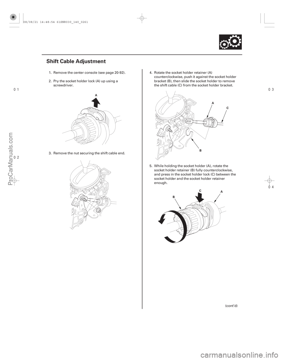
1. Remove the center console (see page 20-92).
2. Pry the socket holder lock (A) up using a
screwdriver.
3. Remove the nut securing the shift cable end. 4. Rotate the socket holder retainer (A)
counterclockwise, push it against the socket holder
bracket (B), then slide the socket holder to remove
the shift cable (C) from the socket holder bracket.
5. While holding the socket holder (A), rotate the socket holder retainer (B) fully counterclockwise,
and press in the socket holder lock (C) between the
socket holder and the socket holder retainer
enough.
(cont’d)
08/08/21 14:48:54 61SNR030_140_0261
ProCarManuals.com
DYNOMITE -2009-