Page 1225 of 2893
���� SPRING SPECIFICATIONS Springs Standard (New)-Unit: mm (in.) Wire Diameter O.D. Free Length No. of Coils
14-303
Main Valve Body Disassembly, Inspe")
���
�(�#�'�������
���
���������
���������
�"�����)���� SPRING SPECIFICATIONS Springs Standard (New)-Unit: mm (in.) Wire Diameter O.D. Free Length No. of Coils
14-303
Main Valve Body Disassembly, Inspection, and Reassembly
ASPRING SEAT
BC RELIEF VALVE
D VALVE SLEEVE
MAIN VALVE BODY CHECK BALLCOOLER CHECK
VALVEFE
LOCK-UP
CONTROL
VALVE
SHIFT VALVE E SHIFT VALVE A
SHIFT VALVE B
SHIFT VALVE C
CHECK BALL
ROLLER
SERVO CONTROL VALVE
MANUAL VALVE
VALVE CAP VALVE CAP CLIP G
H
1. Clean all parts thoroughly in solvent, and dry them with compressed air. Blow out all passages.
2. Do not use a magnet to remove the check balls, it may magnetize the balls.
3. Inspect the valve body for scoring and damage.
4. Check all valves for free movement. If any fail to slide freely, do the valve body repair procedure (see page 14-301).
5. Coat all parts with ATF during assembly.
A Shift valve A spring 0.8 (0.031) 5.6 (0.220) 28.1 (1.106) 15.9B Shift valve B spring 0.8 (0.031) 5.6 (0.220) 28.1 (1.106) 15.9
C Shift valve C spring 0.8 (0.031) 5.6 (0.220) 28.1 (1.106) 15.9
D Relief valve spring 1.0 (0.039) 9.6 (0.378) 34.1 (1.343) 10.2 E Lock-up control valve spring 0.65 (0.026) 7.1 (0.280) 23.1 (0.909) 12.7F Cooler check valve spring 0.85 (0.033) 6.6 (0.260) 27.0 (1.063) 11.3
G Servo control valve spring 0.7 (0.028) 6.6 (0.260) 35.7 (1.406) 17.2 H Shift valve E spring 0.8 (0.031) 5.6 (0.220) 28.1 (1.106) 15.9
08/08/21 14:51:13 61SNR030_140_0305
ProCarManuals.com
DYNOMITE -2009-
Page 1227 of 2893
���� SPRING SPECIFICATIONSSprings Standard (New)-Unit: mm (in.) Wire Diameter O.D. Free Length No. of Coils
14-305
Regulator Valve Body Disassembly")
����
�(�#�'�������
���
���������
���������
�"�����)���� SPRING SPECIFICATIONSSprings Standard (New)-Unit: mm (in.) Wire Diameter O.D. Free Length No. of Coils
14-305
Regulator Valve Body Disassembly, Inspection, and Reassembly
6x1.0mm
12 N·m (1.2 kgf·m, 8.7 lbf·ft)
F G
H 1ST ACCUMULATOR
PISTON
O-RING
REGULATOR VALVE BODY
LOCK-UP SHIFT VALVE
E
VALVE CAP CLIP
VALVE CAP REGULATOR VALVE
TORQUE CONVERTER
CHECK VALVE D
SPRING SEAT A
B
C ACCUMULATOR COVER
3RD ACCUMULATOR PISTON
REGULATOR
SPRING CAP
STOP BOLT
6x1.0mm
12 N·m (1.2 kgf·m,
8.7 lbf·ft) BAFFLE PLATE
1. Clean all parts thoroughly in solvent, and dry them with compressed air. Blow out all passages.
2. Inspect the valve body for scoring and damage.
3. Check all valves for free movement. If any fail to slide freely, do the valve body repair procedure (see page 14-301).
4. Hold the regulator spring cap in place while removing the stop bolt. The regulator spring cap is spring loaded.
5. Coat all parts with ATF during assembly.
6. Replace the O-rings with new ones.
7. When reassembling the valve body, align the hole in the regulator spring cap with the hole in the valve body, then
press the spring cap into the valve body, and tighten the stop bolt.
A Stator reaction spring 4.5 (0.177) 35.4 (1.394) 30.3 (1.193) 1.92 B Regulator valve spring A 1.9 (0.075) 14.7 (0.579) 80.6 (3.173) 16.1
C Regulator valve spring B 1.6 (0.063) 9.2 (0.362) 44.0 (1.732) 12.5
D Torque converter check valve spring 1.2 (0.047) 8.6 (0.339) 33.8 (1.331) 12.2 E Lock-up shift valve spring 1.0 (0.039) 6.6 (0.260) 35.5 (1.398) 18.2F 3rd accumulator spring 2.5 (0.098) 14.6 (0.575) 29.9 (1.177) 4.9
G 1st accumulator spring A 2.4 (0.094) 18.6 (0.732) 49.0 (1.929) 7.1 H 1st accumulator spring B 2.3 (0.091) 12.2 (0.480) 31.5 (1.240) 6.6
Replace.
08/08/21 14:51:14 61SNR030_140_0307
ProCarManuals.com
DYNOMITE -2009-
Page 1230 of 2893
����
Special Tools Required
14-308
Torque Converter Housing
Mainshaft Bearing and Oil Seal Replacement
07736-A01000B or
07736-A01000A
A")
�µ
���
���� ����
�(�#�'�������
���
�����
�
�����������
� �����)����
Special Tools Required
14-308
Torque Converter Housing
Mainshaft Bearing and Oil Seal Replacement
07736-A01000B or
07736-A01000A
A
07749-001000007746-0010500 07749-0010000
07746-0010600
Adjustable bearing puller, 25 40 mm07736-A01000B or 07736-A01000A
Driver 07749-0010000
Attachment, 62 x 68 mm 07746-0010500
Attachment, 72 x 75 mm 07746-0010600
1. Remove the mainshaft bearing and the oil seal using the adjustable bearing puller and a
commercially available 3/8 ’’-16 slide hammer (A).
2. Install a new mainshaft bearing until it bottoms in the housing using the driver and the 62 x 68 mm
attachment. 3. Install a new oil seal flush using the housing using
thedriverandthe72x75mmattachment.
NOTE: Do not drive the seal into the torque
converter housing until it bottoms out; it will block
the fluid return passage and cause transmission
damage.
08/08/21 14:51:16 61SNR030_140_0310
ProCarManuals.com
DYNOMITE -2009-
Page 1232 of 2893
����
Special Tools Required
14-310
Torque Converter Housing
Secondary Shaft Bearing Replacement
6x1.0mm
12 N·m
(1.2 kgf·m, 8.7 lbf")
���
��������
����
�(�#�'�������
���
�����
�
������������� �����)����
Special Tools Required
14-310
Torque Converter Housing
Secondary Shaft Bearing Replacement
6x1.0mm
12 N·m
(1.2 kgf·m, 8.7 lbf·ft)
A
B
B A C
B
A
07749-001000007746-0010500
Driver 07749-0010000
Attachment, 62 x 68 mm 07746-0010500 1. Remove the set plate bolt, then remove the lock washer (A) and the bearing set plate (B).
2. Remove the secondary shaft bearing (A) by heating the housing to about 100 °C (212 °F) using a heat
gun (B). Do not heat the housing more than 100 °C
(212 °F).
NOTE: Let the housing cool to normal temperature
before installing the bearing. 3. Install new O-rings (A) on the ATF guide collar (B),
then install the ATF guide collar in the housing.
4. Install new secondary shaft bearing (C) in the direction shown.
5. Install the secondary shaft bearing using the driver and the 62 x 68 mm attachment, and install it
securely in the housing.
6. Check that the bearing groove aligns with the housing surface, then install the bearing set plate
while aligning the bearing groove.
7. Install a new lock washer and the set plate bolt, then bend the lock tab of the lock washer against
the bolt head.
Replace.
08/08/21 14:51:17 61SNR030_140_0312
ProCarManuals.com
DYNOMITE -2009-
Page 1234 of 2893
����
14-312Shafts and Clutches
Mainshaft Disassembly, Inspection, and Reassembly
LOCKNUT (FLANGE NUT)
24x1.25mm
CONICAL SPRING
WASHER
IDLER GEAR
TR")
����
�(�#�'�������
���
�����
�
�������������"�����)����
14-312Shafts and Clutches
Mainshaft Disassembly, Inspection, and Reassembly
LOCKNUT (FLANGE NUT)
24x1.25mm
CONICAL SPRING
WASHER
IDLER GEAR
TRANSMISSION
HOUSING BEARING
THRUST NEEDLE BEARING
4TH GEAR
NEEDLE BEARING
THRUST NEEDLE BEARING
4TH GEAR COLLAR
4TH/5TH CLUTCH
O-RINGS THRUST WASHER, 41 x 68 mm
NEEDLE BEARING THRUST NEEDLE BEARING 5TH GEAR
THRUST NEEDLE BEARING
SEALING RINGS,
29 mm
NEEDLE BEARING
SET RING
1. Inspect the thrust needle bearing and the needle bearing for galling and r ough movement.
2. Inspect the splines for excessive wear and damage.
3. Check the shaft bearing surface for scoring and excessive wear.
4. Before installing new O-rings, wrap the shaft splines with tape to prevent the O-ring damage.
5. Lubricate all parts with ATF during assembly.
6. Install the conical spring washer and the 41 x 68 mm thrust washer in the direction shown.
7. Replace the locknut and the conical spring washer with new ones when assembling the transmission.
8. Check the clearance of 5th gear (see page 14-313).
Replace. Replace.
Replace. Selective part
Replace.
08/08/21 14:51:18 61SNR030_140_0314
ProCarManuals.com
DYNOMITE -2009-
Page 1235 of 2893
���
����
����
�(�#�'�����������
�����
�
�����������
�"�����)���� �µ�µ
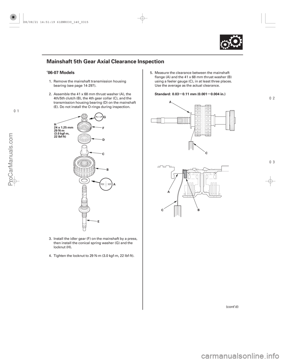
’06-07 Models
Standard: 0.03 0.11 mm (0.001 0.004 in.)
14-313
Mainshaft 5th Gear Axial Clearance Inspection
H
24x1.25mm
29 N·m
(3.0 kgf·m,
22 lbf·ft)
G
F
D
C
B A
E C
A
B
C A
1. Remove the mainshaft transmission housing
bearing (see page 14-297).
2. Assemble the 41 x 68 mm thrust washer (A), the 4th/5th clutch (B), the 4th gear collar (C), and the
transmission housing bearing (D) on the mainshaft
(E). Do not install the O-rings during inspection.
3. Install the idler gear (F) on the mainshaft by a press, then install the conical spring washer (G) and the
locknut (H).
4. Tighten the locknut to 29 N·m (3.0 kgf·m, 22 lbf·ft). 5. Measure the clearance between the mainshaft
flange (A) and the 41 x 68 mm thrust washer (B)
using a feeler gauge (C), in at least three places.
Use the average as the actual clearance.
(cont’d)
08/08/21 14:51:19 61SNR030_140_0315
ProCarManuals.com
DYNOMITE -2009-
Page 1236 of 2893
����
THRUST WASHER, 41 x 68 mm
No. Part Number Thickness
’08-09 Models
14-31414-314Shafts and Clutches
Mainshaft 5th Gear Axial Clearance Inspe")
���
���
�(�#�'�����������
�����
�
�����������
�"�����)����
THRUST WASHER, 41 x 68 mm
No. Part Number Thickness
’08-09 Models
14-31414-314Shafts and Clutches
Mainshaft 5th Gear Axial Clearance Inspection (cont’d)
A
L
E
J
H
G
F
DC
B A
I K
6. If the clearance is out of standard, remove the
41 x 68 mm thrust washer and measure its
thickness (A).
7. Select and install a new thrust washer, then recheck.
1 90414-PRP-000 6.35 mm (0.250 in.)
2 90415-PRP-000 6.40 mm (0.252 in.)
3 90416-PRP-000 6.45 mm (0.254 in.)
4 90417-PRP-000 6.50 mm (0.256 in.)
5 90418-PRP-000 6.55 mm (0.258 in.)
6 90419-PRP-000 6.60 mm (0.260 in.)
8. After replacing the thrust washer, make sure the clearance is within standard.
9. Disassemble the shaft and gears.
10. Reinstall the bearing in the transmission housing (see page 14-298). 1. Remove the mainshaft transmission housing
bearing (see page 14-297).
2. Install the thrust needle bearing (A), 5th gear (B), the needle bearing (C), the thrust needle bearing
(D), the 41 x 68 mm thrust washer (E), the 4th/5th
clutch (F), the 4th gear collar (G), and the
transmission housing bearing (H) on the mainshaft
(I). Do not install the O-rings during inspection.
3. Install the idler gear (J) on the mainshaft by a press, then install the conical spring washer (K) and the
locknut (L).
4. Tighten the locknut to 29 N·m (3.0 kgf·m, 22 lbf·ft).
08/08/21 14:51:19 61SNR030_140_0316
ProCarManuals.com
DYNOMITE -2009-
Page 1238 of 2893
����
14-316Shafts and Clutches
Countershaft Disassembly, Inspection, and Reassembly
LOCKNUT (FLANGE NUT)
24x1.25mm
Left-hand threads
CONICAL SPRING
WA")
���
�(�#�'�������
���
�����
���������������"�����)����
14-316Shafts and Clutches
Countershaft Disassembly, Inspection, and Reassembly
LOCKNUT (FLANGE NUT)
24x1.25mm
Left-hand threads
CONICAL SPRING
WASHER
TRANSMISSION
HOUSING BEARING
4TH GEAR NEEDLE BEARING
PARK GEAR
REVERSE
SELECTOR
REVERSE GEAR
COUNTERSHAFT 3RD GEAR
5TH GEAR 1ST GEAR
2ND GEAR
REVERSE SELECTOR HUB
NEEDLE BEARING
COTTERS, 31 mm SET RING
COLLAR,
37x41x54.3mm COLLAR,
35x47x7.8mm
1. Inspect the needle bearing for galling and r
ough movement.
2. Inspect the splines for excessive wear and damage.
3. Check the shaft bearing surface for scoring and excessive wear.
4. Lubricate all parts with ATF during assembly.
5. Install the conical spring washer, the reverse selector, 35 x 47 x 7.8 mm collar, and all gears in the direction shown.
6. Replace the locknut and the conical spring washer with new ones when assembling the transmission. The countershaft locknut has left-hand threads.
7. Some reverse selector hubs and 3rd gear are press-fitted to the countershaft; special tools are needed to remove
them (see page 14-317) and to install them (see page 14-318).
Replace.
Replace.
08/08/21 14:51:21 61SNR030_140_0318
ProCarManuals.com
DYNOMITE -2009-