Page 1281 of 2893
���� ���
�(�#��������
���
�����
�
���
�������
� �����)�
��
�µ�µ
Standard: 0.05 0.15 mm (0.002 0.006 in.)
14-35614-356 A/T Differential
Backlash In")
���
�(�#�'�������
���
�����
�
���
�������
�"�����)���� ���
�(�#�'�������
���
�����
�
���
�������
� �����)�
��
�µ�µ
Standard: 0.05 0.15 mm (0.002 0.006 in.)
14-35614-356 A/T Differential
Backlash Inspection
Differential Carrier and Final Driven
Gear Replacement
A
B
C
B
A
B
103 N·m (10.5 kgf·m, 75.9 lbf·ft)
10 Bolts
1. Install both axles into the differential, and place the
axles on V-blocks (A).
2. Measure the backlash of the pinion gears (B) using a dial indicator (C).
3. If the backlash is out of standard, replace the differential carrier. NOTE: Inspect and adjust the carrier bearing preload
(see page 14-361) whenever the differential carrier is
replaced.
1. Remove the final driven gear (A) from the differential carrier (B).
NOTE: The final driven gear bolts have left-hand
threads.
2. Install the final driven gear on the differential carrier in the direction shown. Tighten the bolts to
103 N·m (10.5 kgf·m, 75.9 lbf·ft) in a crisscross
pattern in at least two steps.
08/08/21 14:52:43 61SNR030_140_0358
ProCarManuals.com
DYNOMITE -2009-
Page 1296 of 2893
���
���
����
�(�#������������
��������������������� �����)����
16-416-4 Driveline/Axle
Driveshaft Inspection
Driveshaft Removal
F
D B
C
A
E A
B
1.")
���
�(�#�'�����������
���������������������"�����)���
���
����
�(�#�'�����������
��������������������� �����)����
16-416-4 Driveline/Axle
Driveshaft Inspection
Driveshaft Removal
F
D B
C
A
E A
B
1. Check the inboard boot (A) and the outboard boot (B) on the driveshaft (C) for cracks, damage, leaking
grease, and loose boot bands (D). If any damage is
found, replace the boot and the boot bands.
2. Check the driveshaft for cracks and damage. If any damage is found, replace the driveshaft.
3. Check the inboard joint (E) and the outboard joint (F) for cracks and damage. If any damage is found,
replace the inboard joint or the outboard joint as an
assembly.
4. Hold the inboard joint and turn the front wheel by hand, then make sure the joint is not excessively
loose. If necessary, replace the inboard joint or the
outboard joint as an assembly. 1. Raise the vehicle on a lift.
2. Remove the front wheels.
3. Pry up the locking tab (A) on the spindle nut (B),
then remove the nut.
4. Drain the transmission fluid, then reinstall the drain plug with a new sealing washer:
5-speed manual transmission (see page 13-5)
6-speed manual transmission (see page 13-82)
Automatic transmission (see page 14-232)
5. Remove the nuts and the bolt, then separate the lower arm using a prybar.
08/08/21 14:51:21 61SNR030_160_0004
ProCarManuals.com
DYNOMITE -2009-
Page 1314 of 2893

C
12x1.25mm
59 N·m
(6.0 kgf·m,
43 lbf·ft)
D
12x1.25mm
59 N·m
(6.0 kgf·m,
43 lbf·ft)
A
B
5. Clean the areas")
���������
����
16-21
E
D A E
D
A
C B B
A
E
12x1.25mm
59 N·m
(6.0 kgf·m,
43 lbf·ft)
C
12x1.25mm
59 N·m
(6.0 kgf·m,
43 lbf·ft)
D
12x1.25mm
59 N·m
(6.0 kgf·m,
43 lbf·ft)
A
B
5. Clean the areas where the driveshaft contacts the
differential thoroughly with solvent or brake
cleaner, and dry with compressed air.
NOTE: Do not wash the rubber parts with solvent.
6. Insert the inboard end (A) of the driveshaft into the differential (B) or the intermediate shaft (C) until the
set ring (D) locks in the groove (E).
NOTE: Insert the driveshaft horizontally to prevent
damaging the oil seal. 7. Install the outboard joint (A) into the front hub (B).
8. Connect the knuckle (A) onto the lower arm (B).
During installation, install a new flange bolt and
new self-locking nuts. After lightly tightening all
three fasteners, tighten them to the specified
torque in the following order: the nut on the front
(C), the nut on the rear (D), then the bolt (E).
(cont’d)
Replace.
Replace.
Replace.
08/08/21 14:51:44 61SNR030_160_0021
ProCarManuals.com
DYNOMITE -2009-
Page 1320 of 2893
���������
����
�(�#�'�����������
��������������������� �����)����
16-2716-27
Intermediate Shaft Installation
PRESS
B
C
07GAD-PH70201
A
07JAF-SH20400 07965-SD90100 A
B
A
B
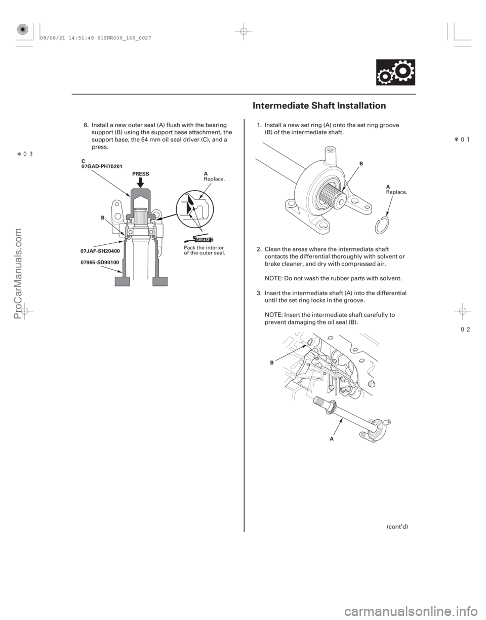
6. Install a new outer seal (A) flush with the bearing
support (B) using the support base attachment, the
support base, the 64 mm oil seal driver (C), and a
press. 1. Install a new set ring (A) onto the set ring groove
(B) of the intermediate shaft.
2. Clean the areas where the intermediate shaft contacts the differential thoroughly with solvent or
brake cleaner, and dry with compressed air.
NOTE: Do not wash the rubber parts with solvent.
3. Insert the intermediate shaft (A) into the differential until the set ring locks in the groove.
NOTE: Insert the intermediate shaft carefully to
prevent damaging the oil seal (B).
(cont’d)
Pack the interior
of the outer seal.Replace.
Replace.
08/08/21 14:51:48 61SNR030_160_0027
ProCarManuals.com
DYNOMITE -2009-
Page 1321 of 2893
���������
����
�(�#�'�����������
��������������������� �����)����
16-2716-27
Intermediate Shaft Installation
PRESS
B
C
07GAD-PH70201
A
07JAF-SH20400 07965-SD90100 A
B
A
B
6. Install a new outer seal (A) flush with the bearing
support (B) using the support base attachment, the
support base, the 64 mm oil seal driver (C), and a
press. 1. Install a new set ring (A) onto the set ring groove
(B) of the intermediate shaft.
2. Clean the areas where the intermediate shaft contacts the differential thoroughly with solvent or
brake cleaner, and dry with compressed air.
NOTE: Do not wash the rubber parts with solvent.
3. Insert the intermediate shaft (A) into the differential until the set ring locks in the groove.
NOTE: Insert the intermediate shaft carefully to
prevent damaging the oil seal (B).
(cont’d)
Pack the interior
of the outer seal.Replace.
Replace.
08/08/21 14:51:48 61SNR030_160_0027
ProCarManuals.com
DYNOMITE -2009-
Page 1324 of 2893
����
Steering
Steering
EPS (Electrical Power Steering) Components
........................................................................................")
�(�#�'�������������������������
�����
�/�����)����
Steering
Steering
EPS (Electrical Power Steering) Components
..............................................................................................................................
..................................................... ................
............................................ ...............
........................................ .................................
.......................................
........................................
.............................................. .................
.....................
................................................................
..............................................................
..................................................... ................
............................................ ...............
........................................ .................................
.......................................
........................................
.............................................. .................
.....................
Special Tools
. 17-2
Component Location Index . 17-3
Steering Wheel Rotational Play Check . 17-4
Power Assist Check . 17-4
Steering Linkage and Gearbox Inspection . 17-5
Steering Wheel Removal . 17-6
Steering Wheel Disassembly/Reassembly . 17-7
Steering Wheel Installation . 17-8
Column Cover Removal and Installation . 17-9
Steering Column Removal and Installation . 17-10
Steering Column Inspection . 17-14
Steering Lock Replacement . 17-14
Rack Guide Adjustment . 17-15
Tie-rod End Ball Joint Boot Replacement . 17-16
Gearbox Mount Cushion Replacement . 17-17
........................................ ...........................
....................................... ..............................
.....................................................
............................................................ .......................................................................................... ......................................
...........................
............................... ......................
........................................
...........................
....................................... ..............................
.....................................................
............................................................ .......................................................................................... ......................................
...........................
............................... ......................
Component Location Index
. 17-18
General Troubleshooting Information . 17-19
Memorizing the Torque Sensor Neutral Position . 17-22
DTC Troubleshooting Index . 17-23
Symptom Troubleshooting Index . 17-25
System Description . 17-26
Circuit Diagram . 17-30
DTC Troubleshooting . 17-33
Symptom Troubleshooting . 17-60
EPS Motor Removal and Installation . 17-63
Steering Gearbox Removal and Installation . 17-65
Rack End Removal and Installation . 17-79
Rack Guide Removal/Installation . 17-83
EPS Control Unit Removal/Installation . 17-84
08/08/21 14:53:09 61SNR030_170_0002
ProCarManuals.com
DYNOMITE -2009-
Page 1325 of 2893
���
���
���
���
�(�#�'�������������������������
�����
�%�����)����Ref. No. Tool Number Description Qty
17-2
Steering
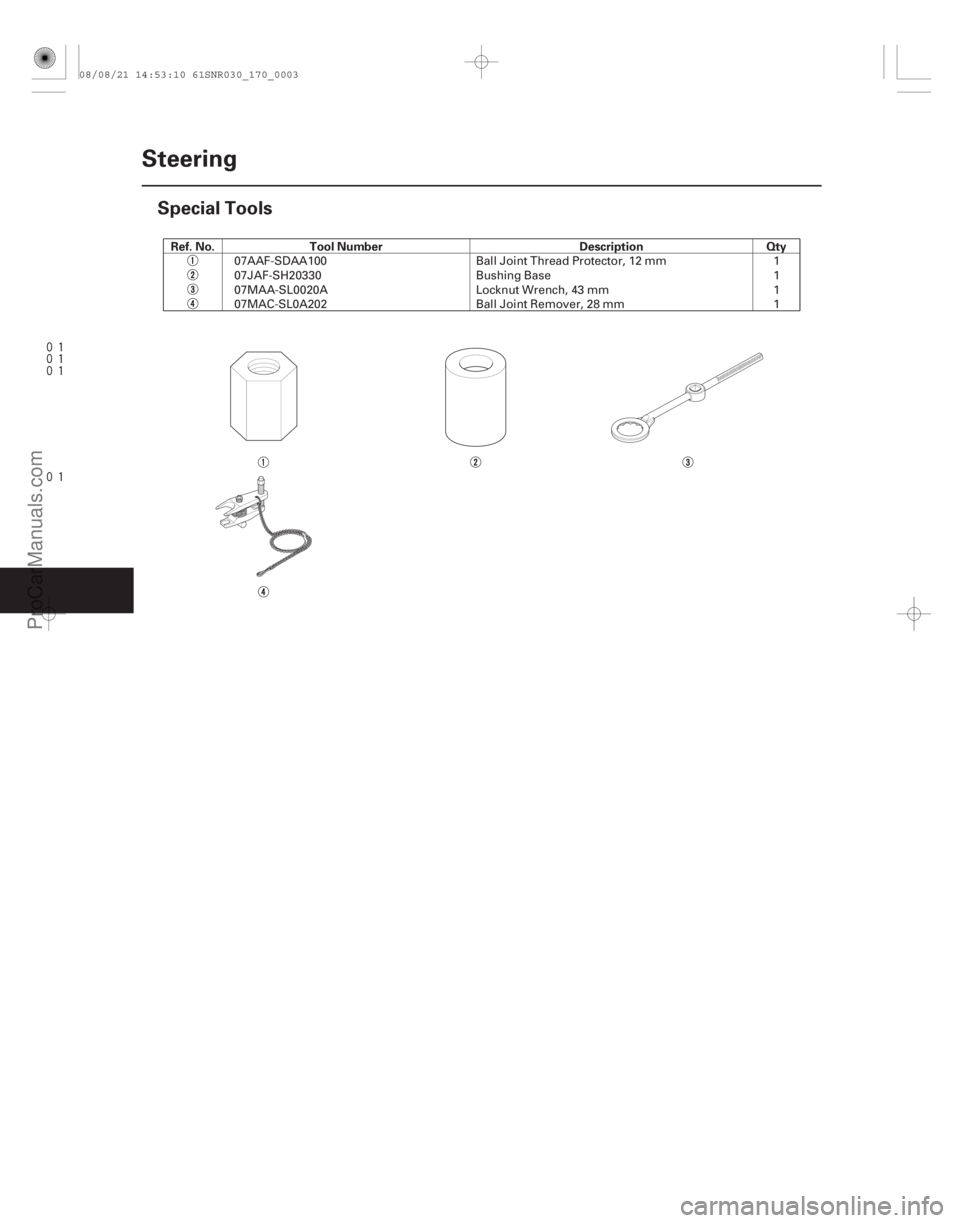
Special Tools
07AAF-SDAA100
Ball Joint Thread Protector, 12 mm 1
07JAF-SH20330 Bushing Base 1
07MAA-SL0020A Locknut Wrench, 43 mm 1
07MAC-SL0A202 Ball Joint Remover, 28 mm 1
08/08/21 14:53:10 61SNR030_170_0003
ProCarManuals.com
DYNOMITE -2009-
Page 1326 of 2893
����
�(�#�'���������������������������������������)����
17-3
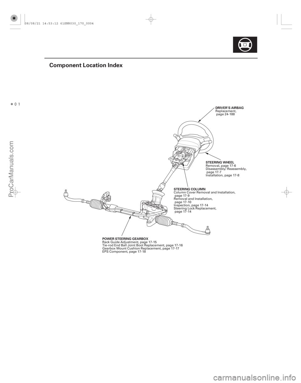
Component Location Index
DRIVER’S AIRBAG
POWER STEERING GEARBOX STEERING COLUMN
STEERING WHEELReplacement,
page 24-188
Rack Guide Adjustment, page 17-15
Tie-rod End Ball Joint Boot Replacement, page 17-16
Gearbox Mount Cushion Replacement, page 17-17
EPS Component, page 17-18 Column Cover Removal and Installation,
page 17-9
Removal and Installation, page 17-10
Inspection, page 17-14
Steering Lock Replacement, page 17-14 Removal, page 17-6
Disassembly/ Reassembly,
page 17-7
Installation, page 17-8
08/08/21 14:53:12 61SNR030_170_0004
ProCarManuals.com
DYNOMITE -2009-