Page 1373 of 2893
���
�µ
�µ
�µ
�µ �µ
�µ
�µ
�µ
DTC 51-02:
DTC 51-03:
DTC 51-06:
DTC 51-07:
YES
NO
YES
NO YES
NO
YES
NO
17-50EPS Components
DTC Tro")
�µ
�µ
���
����
�(�#�'��������� �������������'���
�����������)���
�µ
�µ
�µ
�µ �µ
�µ
�µ
�µ
DTC 51-02:
DTC 51-03:
DTC 51-06:
DTC 51-07:
YES
NO
YES
NO YES
NO
YES
NO
17-50EPS Components
DTC Troubleshooting (cont’d)
EPS CONTROL UNIT CONNECTOR D (28P)
PVF (BRN) VS1 (GRN)
EPS CONTROL UNIT CONNECTOR D (28P)
PVF (BRN)
VS2 (LT GRN)
Torque Sensor (VT3 Differential-
amplification Function) (Regular Diagnosis)
Torque Sensor (VT1, VT2 Rapid
Change) (Regular Diagnosis)
Torque Sensor (VT1, VT2
Average) (Regular Diagnosis)
Torque Sensor (VT1, VT2 Initial
Check) (Initial Diagnosis)
1. Turn the ignition switch to ON (II).
2. Clear the DTC with the HDS.
3. Turn the ignition switch to LOCK (0).
4. Start the engine.
Go to step 5.
Check for loose terminals or poor connections.
If the connections are good, the system is OK at
this time.
5. Check for DTCs with the HDS.
Go to step 6.
Troubleshoot the indicated DTC. If there are
no DTCs, the system is OK at this time.
6. Turn the ignition switch to LOCK (0). 7. Disconnect EPS control unit connector D (28P).
8. Measure the resistance between EPS control unit
connector D (28P) terminals No. 9 and No. 10.
Go to step 9.
Go to step 13.
9. Measure the resistance between EPS control unit connector D (28P) terminals No. 8 and No. 9.
Go to step 10.
Go to step 15.
Wire side of female terminals
Wire side of female terminals
Does t he E PS i nd i cat or come on?
I s DT C 5 1-02, 5 1-03, 5 1-06, or 5 1-07 i nd i cat ed ? Is t he r esi st ance bet w een 12 15 ?
Is t he r esi st ance bet w een 12 15 ?
08/08/21 14:54:35 61SNR030_170_0051
ProCarManuals.com
DYNOMITE -2009-
Page 1376 of 2893
����
�µ
�µ
�µ
�µ �µ
�µ
DTC 61-04:
YES
NO
YES
NO YES
NO
17-53
EPS CONTROL UNIT
CONNECTOR B
EPS CONTROL UNIT
CONNECTOR C
No. 1
No. 2
No. 1
No.")
����
�(�#�'��������� �������������'���
�����������)����
�µ
�µ
�µ
�µ �µ
�µ
DTC 61-04:
YES
NO
YES
NO YES
NO
17-53
EPS CONTROL UNIT
CONNECTOR B
EPS CONTROL UNIT
CONNECTOR C
No. 1
No. 2
No. 1
No. 2
No. 1
No. 1
EPS CONTROL UNIT CONNECTOR B (2P)
H-V (BLU)
H-U (RED) H-W (GRN)
EPS CONTROL UNIT CONNECTOR C (2P)
Open/Short in EPS Motor Harness
(Steering Diagnosis)
1. Turn the ignition switch to ON (II).
2. Clear the DTC with the HDS.
3. Turn the ignition switch to LOCK (0).
4. Start the engine.
5. Turn the steering wheel to the right or left, and wait
10 seconds or more.
Go to step 6.
Check for loose terminals or poor connections.
If the connections are good, the system is OK at
this time.
6. Check for DTCs with the HDS.
Go to step 7.
Troubleshoot the indicated DTC. If there are
no DTCs, the system is OK at this time.
7. Turn the ignition switch to LOCK (0).
8. Disconnect the EPS control unit connector B (2P) and connector C (2P). 9. Check for continuity between the following
terminals of the EPS control unit connector B (2P)
and connector C (2P).
Go to step 10.
Go to step 13.
(cont’d)
Wire side of female terminals
Wire side of female terminals
Does t he E PS i nd i cat or come on? Is DT C 61-04 indicated? Is there continuity?
08/08/21 14:54:36 61SNR030_170_0054
ProCarManuals.com
DYNOMITE -2009-
Page 1378 of 2893
����
�µ
�µ �µ
�µ
�µ
�µ
YES
NO
YES
NO
YES
NO
DTC 71-01:
DTC 71-02:
DTC 71-03:
DTC 71-05:
DTC 71-06:
17-5517-55
No. 1
No. 2
No. 1
No. 2
H-W (R")
�����
�(�#�'��������� �������������'���
���
�������)����
�µ
�µ �µ
�µ
�µ
�µ
YES
NO
YES
NO
YES
NO
DTC 71-01:
DTC 71-02:
DTC 71-03:
DTC 71-05:
DTC 71-06:
17-5517-55
No. 1
No. 2
No. 1
No. 2
H-W (RED)
H-U (BLK)
H-V (WHT)
EPS MOTOR
1P CONNECTOR
EPS MOTOR
2P CONNECTOR
No. 1
No. 1
EPS MOTOR 2P CONNECTOR
EPS MOTOR 1P CONNECTOR
13. Disconnect the EPS motor 1P connector and the
EPS motor 2P connector.
14. On the EPS motor side, check for continuity between the following terminals of the EPS motor
1P and the EPS motor 2P connector.
Repair open in the wire between the EPS
control unit and the EPS motor.
Open in the EPS motor wire, or EPS motor
internal circuit, replace the EPS motor (see page
17-63). 1. Turn the ignition switch to ON (II).
2. Clear the DTC with the HDS.
3. Turn the ignition switch to LOCK (0).
4. Start the engine.
5. Turn the steering wheel to the right or left, and wait
10 seconds or more.
Go to step 6.
Check for loose terminals or poor connections.
If the connections are good, the system is OK at
this time.
6. Check for DTCs with the HDS.
Go to step 7.
Troubleshoot the indicated DTC. If there are
no DTCs, the system is OK at this time.
7. Turn the ignition switch to LOCK (0).
8. Disconnect EPS control unit connector D (28P).
(cont’d)EPS Motor Angle Sensor (SIN/
COS Signals) (Steering Diagnosis)
EPS Motor Angle Sensor (Neutral
Position Learning of SIN/COS) (Initial
Diagnosis)
EPS Motor Angle Sensor (SIN/
COS Signals) (Steering Diagnosis)
EPS Motor Angle Sensor (SIN/
COS Signals Charging Amount) (Steering
Diagnosis)
EPS Motor Angle Sensor (Neutral
Position of SIN/COS) (Initial Diagnosis)
Terminal side of male terminal
Terminal side of male terminals
Is there continuity? Does t he E PS i nd i cat or come on?
Is DT C 7 1-01, 7 1-02, 7 1-03, 7 1-05 or 7 1-06indicated?
08/08/21 14:54:37 61SNR030_170_0056
ProCarManuals.com
DYNOMITE -2009-
Page 1381 of 2893
����
�µ
�µ
�µ
�µ �µ
�µ
�µ
�µ
DTC 71-04:
YES
NO
YES
NO YES
NO
YES
NO
17-58EPS Components
DTC Troubleshooting (cont’d)
EPS CONTROL U")
�µ
���
����
�(�#�'��������� �������������'���
�����������)����
�µ
�µ
�µ
�µ �µ
�µ
�µ
�µ
DTC 71-04:
YES
NO
YES
NO YES
NO
YES
NO
17-58EPS Components
DTC Troubleshooting (cont’d)
EPS CONTROL UNIT CONNECTOR D (28P)
R1 (BLU)
R2 (PNK)
EPS CONTROL UNIT CONNECTOR D (28P) R1 (BLU)
R2 (PNK)
EPS Motor Angle Sensor (Check
Signals) (Regular Diagnosis)
1. Turn the ignition switch to ON (II).
2. Clear the DTC with the HDS.
3. Turn the ignition switch to LOCK (0).
4. Start the engine.
5. Turn the steering wheel to the right or left, and wait
10 seconds or more.
Go to step 6.
Check for loose terminals or poor connections.
If the connections are good, the system is OK at
this time.
6. Check for DTCs with the HDS.
Go to step 7.
Troubleshoot the indicated DTC. If there are
no DTCs, the system is OK at this time.
7. Turn the ignition switch to LOCK (0).
8. Disconnect the EPS control unit connector D (28P). 9. Measure the resistance between the EPS control
unit connector D (28P) terminal No. 13 and No. 27.
Go to step 10.
Go to step 13.
10. Check for continuity between body ground and the EPS control unit connector D (28P) terminal No. 13
and the terminal No. 27 individually.
Go to step 11.
Check for loose terminals in the EPS control
unit connectors, and repair if necessary. If no poor
connections are found, replace the EPS control unit
(see page 17-84).
Wire side of female terminals
Wire side of female terminalsDoes t he E PS i nd i cat or come on?
Is DTC 71-04 indicated? Is t he r esi st ance bet w een 13 25 ?
Is there continuity?
08/08/21 14:54:38 61SNR030_170_0059
ProCarManuals.com
DYNOMITE -2009-
Page 1383 of 2893
����
����
�(�#������������
���
�����������������������)����
�µ
�µ
�µ
�µ
�µ
�µ
EPS indicator does not come on EPS indicator does not go off, and")
�(�#�'�����������
���
�����������������������)����
����
�(�#�'�����������
���
�����������������������)����
�µ
�µ
�µ
�µ
�µ
�µ
EPS indicator does not come on EPS indicator does not go off, and no DTCs
are stored
YES
NO
YES
NO
YES
NO
17-6017-60EPS Components
Symptom Troubleshooting
EPS CONTROL UNIT CONNECTOR D (28P)
IG1 (YEL)* (GRY)*
*1: ’06 model
*2: ’07-09 models
12
1. Turn the ignition switch to ON (II), and watch the EPS indicator.
The system is OK at this time.
Troubleshoot the gauge control module (tach)
(see page 22-241). NOTE: Check for gauge DTCs with the HDS (see page
22-3). If gauge DTCs are stored, troubleshoot those
DTCs first.
1. Turn the ignition switch to LOCK (0).
2. Check the No. 4 (7.5 A) fuse in the under-dash fuse/ relay box.
Reinstall the checked fuse, then go to step 5.
Go to step 3.
3. Disconnect EPS control unit connector D (28P).
4. Check for continuity between EPS control unit connector D (28P) terminal No. 16 and body ground.
Repair short to body ground in the wire
between the EPS control unit and the No. 4 (7.5 A)
fuse in the under-dash fuse/relay box.
Install a new No. 4 (7.5 A) fuse in the under-
dashfuse/relaybox,thengotostep5.
Wire side of female terminals
Does t he E PS i nd i cat or come on?
IsthefuseOK?
Is there continuity?
08/08/21 14:55:07 61SNR030_170_0061
ProCarManuals.com
DYNOMITE -2009-
Page 1384 of 2893

IG1 (YEL)* (GRY)*
*1: ’06 model
*2: ’07-09 models EPS CONTROL UNIT CONNECTOR A (2P)
PG (BLK)
12
5.")
���������
�µ
�µ
�µ
�µ �µ
�µ
YES
NO
YES
NO YES
NO
17-61
EPS CONTROL UNIT CONNECTOR D (28P)
IG1 (YEL)* (GRY)*
*1: ’06 model
*2: ’07-09 models EPS CONTROL UNIT CONNECTOR A (2P)
PG (BLK)
12
5. Reconnect EPS control unit connector D (28P).
6. Turn the ignition switch to ON (II), and watch theEPS indicator.
Troubleshooting is complete.
Replace the EPS control unit (see page 17-84).
7. Disconnect EPS control unit connector D (28P).
8. Turn the ignition switch to ON (II).
9. Measure the voltage between EPS control unit connector D (28P) terminal No. 16 and body ground.
Go to step 10.
Repair open in the wire between the EPS
control unit and under-dash fuse/relay box.
10. Turn the ignition switch to LOCK (0).
11. Disconnect EPS control unit connector A (2P). 12. Check for continuity between EPS control unit
connector A (2P) terminal No. 1 and body ground.
Go to step 13.
Repair open in the wire between the EPS
control unit and body ground (G 402).
(cont’d)
Wire side of female terminals Wire side of female terminals
Does the EPS indicator come on, then go of f ?
Is there battery voltage? Is there continuity?
08/08/21 14:55:07 61SNR030_170_0062
ProCarManuals.com
DYNOMITE -2009-
Page 1389 of 2893

A
B
C D
A
8x1.25mm B
A
7. Release the lock lever, and adjust the steering column to the full tilt up position, an")
���
����
����
17-66EPS Components
Steering Gearbox Removal and Installation (cont’d)
A
B
C D
A
8x1.25mm B
A
7. Release the lock lever, and adjust the steering column to the full tilt up position, and to the full
telescopic in position.
8. Tighten the lock lever.
9. Hold the lower slide shaft (A) on the column with a piece of wire (B) between the joint yoke (C) of the
lower slide shaft and joint yoke (D) of the upper
shaft to prevent the slider shaft from pulling out.
10. Release the lock lever, and adjust the steering column to the full telescopic out position, then
tighten the lock lever. 11. Remove the steering joint bolt (A), and disconnect
the steering joint by moving the steering joint (B)
toward the column.
12. Remove the center guide (A) (if equipped), and discard it. The center guide is for factory assembly
use only.
13. Remove the cowl cover and under cowl panel (see page 20-163).
14. Remove the air cleaner housing (see page 11-345).
08/08/21 14:55:10 61SNR030_170_0067
ProCarManuals.com
DYNOMITE -2009-
Page 1391 of 2893
����
�������
�
��
17-68EPS Components
Steering Gearbox Removal and Installation (cont’d)
A
12x1.25mm
B
12 x 1.25 mm
A BA
BB
A
A
VSB02C000016 B
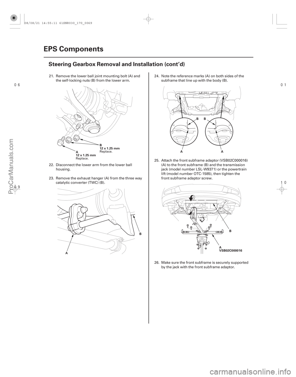
21. Remove the lower ball joint mounting bolt (A) and
the self-locking nuts (B) from the lower arm.
22. Disconnect the lower arm from the lower ball housing.
23. Remove the exhaust hanger (A) from the three way catalytic converter (TWC) (B). 24. Note the reference marks (A) on both sides of the
subframe that line up with the body (B).
25. Attach the front subframe adaptor (VSB02C000016) (A) to the front subframe (B) and the transmission
jack (model number LSL-W9371) or the powertrain
lift (model number OTC-1585), then tighten the
front subframe adaptor screw.
26. Make sure the front subframe is securely supported by the jack with the front subframe adaptor.
Replace. Replace.
08/08/21 14:55:11 61SNR030_170_0069
ProCarManuals.com
DYNOMITE -2009-