Page 1415 of 2893
 Turning angle:
Inward wheel: 38 ° 46 ’ 2 °
Outward wheel (reference): 31 ° 14 ’2")
��������
�´
�µ �´
�µ�
Rear Toe Inspection/Adjustment Turning Angle Inspection
Rear toe-in: 2 mm (0.08 in.) Turning angle:
Inward wheel: 38 ° 46 ’ 2 °
Outward wheel (reference): 31 ° 14 ’2 1 0.08
0.04
18-8Front and Rear Suspension
Wheel Alignment (cont’d)
A
B
C
Except Type S model:
12x1.25mm
69 N·m
(7.0 kgf·m, 51 lbf·ft)
Type S model:
12x1.25mm
74 N·m
(7.5 kgf·m, 54 lbf·ft)
Use commercially available computerized four wheel
alignment equipment to measure wheel alignment
(caster, camber, toe, and turning angle). Follow the
equipment manufacturer’s instructions.
1. Release the parking brake to avoid an incorrect measurement.
2. Check the toe.
If adjustment is required, go to step 3.
If no adjustment is required, go to turning angleinspection.
3. Hold the adjusting bolt (A) on the trailing arm (B), and loosen the self-locking nut (C).
4. Replace the self-locking nut with a new one, and lightly tighten it.
NOTE: Always use a new self-locking nut whenever it has been tightened to the specified torque.
Reassemble the adjusting bolt and the adjusting cam plate with the eccentric facing up.
5. Adjust the rear toe by turning the adjusting bolt until the toe is correct.
6. Tighten the self-locking nut to the specified torque value while holding the adjusting bolt. Use commercially available computerized four wheel
alignment equipment to measure wheel alignment
(caster, camber, toe, and turning angle). Follow the
equipment manufacturer’s instructions.
1. Turn the wheel right and left while applying the brake, and measure the turning angle of both
wheels.
2. If the measurement is not within the specifications, even up both sides of the tie-rod threaded section
length while adjusting the front toe. If it is correct,
but the turning angle is not within the
specifications, check for bent or damaged
suspension components.
Replace.
Replace.
08/08/21 14:56:46 61SNR030_180_0008
ProCarManuals.com
DYNOMITE -2009-
Page 1422 of 2893
����
�(�#�'�������������������������������
� �����)����
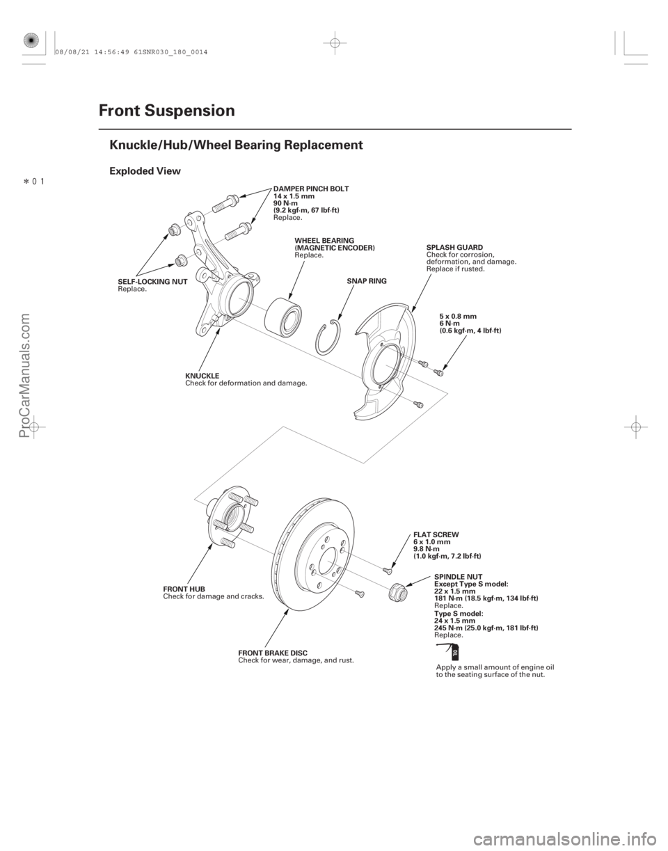
Exploded View
18-14Front Suspension
Knuckle/Hub/Wheel Bearing Replacement
SNAP RING
SELF-LOCKING NUT DAMPER PINCH BOLT
14x1.5mm
90 N·m
(9.2 kgf·m, 67 lbf·ft)
WHEEL BEARING
(MAGNETIC ENCODER) SPLASH GUARD
KNUCKLE
FLAT SCREW
6x1.0mm
9.8 N·m
(1.0 kgf·m, 7.2 lbf·ft)
FRONT HUB
FRONT BRAKE DISC SPINDLE NUT
Except Type S model:
22 x 1.5 mm
181 N·m (18.5 kgf·m, 134 lbf·ft)5x0.8mm
6N·m
(0.6 kgf·m, 4 lbf·ft)
Type S model:
24 x 1.5 mm
245 N·m (25.0 kgf·m, 181 lbf·ft)
Replace.
Replace.
Replace. Check for corrosion,
deformation, and damage.
Replace if rusted.
Check for deformation and damage.
Apply a small amount of engine oil
to the seating surface of the nut.
Check for damage and cracks.
Check for wear, damage, and rust. Replace.
Replace.
08/08/21 14:56:49 61SNR030_180_0014
ProCarManuals.com
DYNOMITE -2009-
Page 1424 of 2893

A
B
Except Type S model:
22x1.5mm
181 N·m
(18.5 kgf·m, 134 lbf·ft)
Type S model:
24x1.5mm
245 N·m
(25.0 kgf")
����
����� ����
18-16Front Suspension
Knuckle/Hub/Wheel Bearing Replacement (cont’d)
A
B
Except Type S model:
22x1.5mm
181 N·m
(18.5 kgf·m, 134 lbf·ft)
Type S model:
24x1.5mm
245 N·m
(25.0 kgf·m, 181 lbf·ft)
B
12x1.25mm
54 N·m
(5.5 kgf·m,
40 lbf·ft)
A
07MAC-SL0A20207AAF-SDAA100 D
12x1.25mm
59 N·m
(6.0 kgf·m,
43 lbf·ft)
B
12x1.25mm
59 N·m
(6.0 kgf·m, 43 lbf·ft)
C
12x1.25mm
59 N·m (6.0 kgf·m, 43 lbf·ft) A
E
6. Raise the stake (A), then remove the spindle nut (B).
7. Remove the front brake disc (see page 19-21).
8. Check the front hub for damage and cracks.
9. Remove the cotter pin (A) from the tie-rod end ball joint, then remove the nut (B).
NOTE: During installation, install a new cotter pin
after tightening the nut, and bend its end as shown. 10. Disconnect the tie-rod end ball joint from the
knuckle using the ball joint thread protector and the
ball joint remover (see page 18-12).
11. Remove the flange bolt and the self-locking nuts from the lower arm (A).
NOTE: During installation, install the new flange
bolt and the new self-locking nuts. After lightly
tightening all three fasteners, tighten them to the
specified torque in the following order; the nut on
the front (B), the nut on the rear (C), then the bolt
(D).
12. Disconnect the lower ball joint (E) from the lower arm.
Replace.
Replace.
Replace. Replace.
Replace.
Replace.
08/08/21 14:56:50 61SNR030_180_0016
ProCarManuals.com
DYNOMITE -2009-
Page 1425 of 2893

B
AC
07MAC-SL0A102
B
14x2.0mm
69 78 N·m
(7.0 8.0 kgf·m,
51 58 lbf·ft)
071AF-S3VA000
13. Remove the damper pinch bolts (A")
��������
�µ
�µ
�µ
18-17
C
D E
A
14x1.5mm
90 N·m
(9.2 kgf·m,
67 lbf·ft)
B
AC
07MAC-SL0A102
B
14x2.0mm
69 78 N·m
(7.0 8.0 kgf·m,
51 58 lbf·ft)
071AF-S3VA000
13. Remove the damper pinch bolts (A) and the self-locking nuts (B) from the damper.
NOTE: Use new damper pinch bolts and new self-
locking nuts during reassembly.
14. Remove the driveshaft outboard joint (C) from the knuckle (D) by tapping the driveshaft end (E) with a
soft face hammer while drawing the hub outward,
then remove the knuckle.
NOTE: Do not pull the driveshaft end outward. The driveshaft inboard joint may come apart.
During installation, apply grease to the mating surfaces of the wheel bearing and the driveshaft
outboard joint (see step 1 on page 16-20). 15. Remove the lock pin (A) from the lower ball joint,
then remove the castle nut (B).
NOTE: During installation, install a lock pin as
shown after tightening the new castle nut.
16. Disconnect the lower ball joint (C) from the knuckle using the ball joint thread protector and the ball
joint remover (see page 18-12).
(cont’d)
Replace.
Replace.
Replace.
08/08/21 14:56:51 61SNR030_180_0017
ProCarManuals.com
DYNOMITE -2009-
Page 1428 of 2893
���� Special Tools Required
18-2018-20 Front Suspension
Knuckle/Hub/Wheel Bearing
Replacement (cont’d)
Lower Ball Joint Replacement
D
5x0.")
�
��
�
�
���
�(�#�'�����������������������
��������� �����)���� Special Tools Required
18-2018-20 Front Suspension
Knuckle/Hub/Wheel Bearing
Replacement (cont’d)
Lower Ball Joint Replacement
D
5x0.8mm
6N·m
(0.6 kgf·m, 4 lbf·ft)
C
A B
A
Press
07746-0010500
B 07749-0010000
C
07965-SD90100 B
12x1.25mm
59 N·m (6.0 kgf·m, 43 lbf·ft)
C
12x1.25mm
59N·m(6.0kgf·m,43lbf·ft) A
D
12x1.25mm
59 N·m (6.0 kgf·m, 43 lbf·ft) E
7. Install the snap ring (A) securely in the knuckle (B).
8. Install the splash guard (C), and tighten the screws
(D) to the specified torque value.
9. Install the hub (A) onto the knuckle (B) using the attachment, the driver handle, the support base,
and a hydraulic press. Be careful not to damage the
splash guard (C). Ball joint remover, 32 mm 07MAC-SL0A102
Ball joint thread protector, 14 mm 071AF-S3VA000
1. Remove the front wheel.
2. Remove the flange bolt and the self-locking nuts from the lower arm (A).
NOTE: During installation, install the new flange
bolt and the new self-locking nuts. After lightly
tightening all three fasteners, tighten them to the
specified torque in the following order; the nut on
the front (B), the nut on the rear (C), then the bolt
(D).
3. Disconnect the lower ball joint (E) from the lower arm.
Replace.
Replace.
Replace.
08/08/21 14:56:52 61SNR030_180_0020
ProCarManuals.com
DYNOMITE -2009-
Page 1429 of 2893
���� Special Tools Required
18-2018-20 Front Suspension
Knuckle/Hub/Wheel Bearing
Replacement (cont’d)
Lower Ball Joint Replacement
D
5x0.")
�
��
�
�
���
�(�#�'�����������������������
��������� �����)���� Special Tools Required
18-2018-20 Front Suspension
Knuckle/Hub/Wheel Bearing
Replacement (cont’d)
Lower Ball Joint Replacement
D
5x0.8mm
6N·m
(0.6 kgf·m, 4 lbf·ft)
C
A B
A
Press
07746-0010500
B 07749-0010000
C
07965-SD90100 B
12x1.25mm
59 N·m (6.0 kgf·m, 43 lbf·ft)
C
12x1.25mm
59N·m(6.0kgf·m,43lbf·ft) A
D
12x1.25mm
59 N·m (6.0 kgf·m, 43 lbf·ft) E
7. Install the snap ring (A) securely in the knuckle (B).
8. Install the splash guard (C), and tighten the screws
(D) to the specified torque value.
9. Install the hub (A) onto the knuckle (B) using the attachment, the driver handle, the support base,
and a hydraulic press. Be careful not to damage the
splash guard (C). Ball joint remover, 32 mm 07MAC-SL0A102
Ball joint thread protector, 14 mm 071AF-S3VA000
1. Remove the front wheel.
2. Remove the flange bolt and the self-locking nuts from the lower arm (A).
NOTE: During installation, install the new flange
bolt and the new self-locking nuts. After lightly
tightening all three fasteners, tighten them to the
specified torque in the following order; the nut on
the front (B), the nut on the rear (C), then the bolt
(D).
3. Disconnect the lower ball joint (E) from the lower arm.
Replace.
Replace.
Replace.
08/08/21 14:56:52 61SNR030_180_0020
ProCarManuals.com
DYNOMITE -2009-
Page 1430 of 2893
�������
�µ
�µ
�µ
18-21
A B
C A
B
14x2.0mm
69 78 N·m
(7.0 8.0 kgf·m,
51 58 lbf·ft)
07MAC-SL0A102
071AF-S3VA000
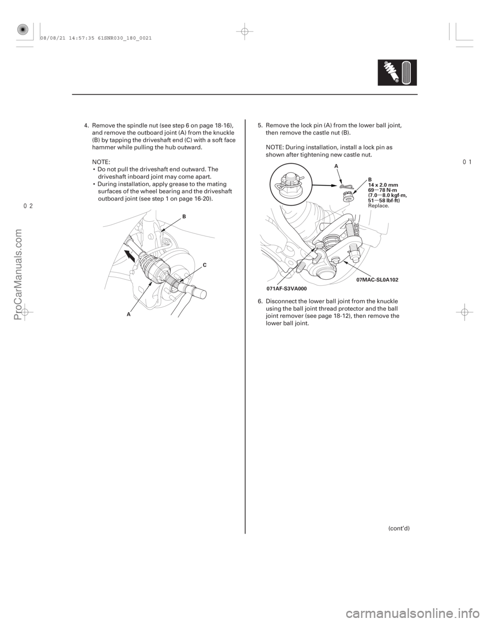
4. Remove the spindle nut (see step 6 on page 18-16), and remove the outboard joint (A) from the knuckle
(B) by tapping the driveshaft end (C) with a soft face
hammer while pulling the hub outward.
NOTE: Do not pull the driveshaft end outward. The driveshaft inboard joint may come apart.
During installation, apply grease to the mating surfaces of the wheel bearing and the driveshaft
outboard joint (see step 1 on page 16-20). 5. Remove the lock pin (A) from the lower ball joint,
then remove the castle nut (B).
NOTE: During installation, install a lock pin as
shown after tightening new castle nut.
6. Disconnect the lower ball joint from the knuckle using the ball joint thread protector and the ball
joint remover (see page 18-12), then remove the
lower ball joint.
(cont’d)
Replace.
08/08/21 14:57:35 61SNR030_180_0021
ProCarManuals.com
DYNOMITE -2009-
Page 1433 of 2893

C
12x1.25mm
59N·m(6.0kgf·m,43lbf·ft) A
D
12x1.25mm
59 N·m (6.0 kgf·m, 43 lbf·ft) E D
C
B
12x1.25mm
64 N·m
(6.5 kgf·m, 47 lbf·ft)
A")
���
����
18-23
B
12x1.25mm
59 N·m (6.0 kgf·m, 43 lbf·ft)
C
12x1.25mm
59N·m(6.0kgf·m,43lbf·ft) A
D
12x1.25mm
59 N·m (6.0 kgf·m, 43 lbf·ft) E D
C
B
12x1.25mm
64 N·m
(6.5 kgf·m, 47 lbf·ft)
A
14x1.5mm
83 N·m
(8.5 kgf·m, 61 lbf·ft)
5. Remove the flange bolt and the self-locking nuts
from the lower arm (A).
NOTE: During installation, install the new flange
bolt and the new self-locking nuts. After lightly
tightening all three fasteners, tighten them to the
specified torque in the following order, the nut on
the front (B), the nut on the rear (C), then the bolt
(D).
6. Disconnect the lower ball joint (E) from the lower arm. 7. Remove the front side of the lower arm mounting
bolt (A).
NOTE: Use the new mounting bolt during
reassembly.
8. Remove the rear side of the lower arm mounting bolt (B), then remove the lower arm (C) from the
front suspension subframe (D).
NOTE: Use the new mounting bolt during
reassembly.
9. Install the lower arm in the reverse order of removal, and note these items:
First install all of the components, and lightly tighten the bolts and the nuts, then raise the
suspension to load it with the vehicle’s weight
before fully tightening to the specified torque
values.
Before installing the wheel, clean the mating surfaces of the brake disc and the inside of the
wheel.
10. Check the wheel alignment, and adjust it if necessary (see page 18-5).
(cont’d)
Replace.
Replace.
Replace. Replace.
Replace.
08/08/21 14:57:36 61SNR030_180_0023
ProCarManuals.com
DYNOMITE -2009-