Page 1448 of 2893
����
18-3718-37
Stabilizer Link Removal/Installation
A
Except Type S model:
10x1.25mm
39 N·m
(4.0 kgf·m, 29 lbf·ft) C
D E
F
GH
B
10x1.25mm
39 N·m")
���
�(�#�'���������������
���������������
� �����)����
18-3718-37
Stabilizer Link Removal/Installation
A
Except Type S model:
10x1.25mm
39 N·m
(4.0 kgf·m, 29 lbf·ft) C
D E
F
GH
B
10x1.25mm
39 N·m
(4.0 kgf·m, 29 lbf·ft)
Type S model:
10x1.25mm
38 N·m
(3.9 kgf·m, 28 lbf·ft)
11. Install the trailing arm in the reverse order of
removal, and note these items:
First install all of the components, and lightly tighten the bolts, then raise the suspension to
load it with the vehicle’s weight before fully
tightening to the specified torque values.
Check the brake hose for interference and twisting.
Before installing the wheel, clean the mating surfaces on the brake disc and the inside of the
wheel.
12. Check the wheel alignment, and adjust it if necessary (see page 18-5). 1. Raise the rear of the vehicle, and support it with
safety stands in the proper locations (see page
1-11).
2. Remove the rear wheel.
3. Remove the self-locking nut (A) and the flange nut (B) while holding the respective joint pin (C) with a
hex wrench (D), then remove the stabilizer link (E).
4. Install the stabilizer link on the stabilizer bar (F) and trailing arm (G) with the joint pins set at the center
of their range of the movement.
NOTE: The stabilizer link has a paint mark (H). Align
the paint mark on the stabilizer link facing rearward.
5. Install the new self-locking nut and the new flange nut, and tighten them to the specified torque values
while holding the respective joint pin with a hex
wrench.
6. Clean the mating surfaces of the brake disc and the inside of the wheel, then install the rear wheel.
7. Test-drive the vehicle.
8. After 5 minutes of driving, torque the self-locking nut again to the specified torque values.
Replace.
Replace.
Replace.
08/08/21 14:57:44 61SNR030_180_0037
ProCarManuals.com
DYNOMITE -2009-
Page 1450 of 2893
���
�(�#�'���������������
�������
���
����� �����)����
Exploded View
18-39
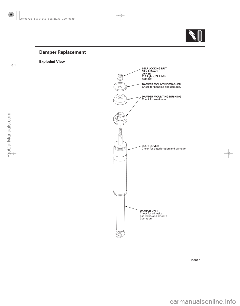
Damper Replacement
SELF LOCKING NUT
10x1.25mm
29 N·m
(3.0 kgf·m, 22 lbf·ft)DAMPER MOUNTING WASHER
DAMPER MOUNTING BUSHING
DAMPER UNIT DUST COVER
(cont’d)
Replace.
Check for bending and damage.
Check for weakness.
Check for oil leaks,
gas leaks, and smooth
operation. Check for deterioration and damage.
08/08/21 14:57:45 61SNR030_180_0039
ProCarManuals.com
DYNOMITE -2009-
Page 1451 of 2893
����
��������
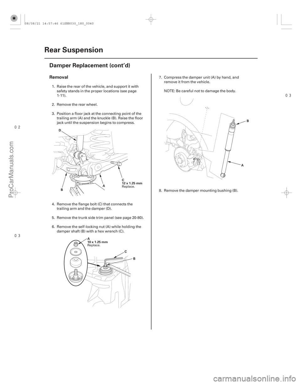
Removal
18-40Rear Suspension
Damper Replacement (cont’d)
C
12x1.25mm
A
B
D
A
10x1.25mm B
C A
B
1. Raise the rear of the vehicle, and support it with
safety stands in the proper locations (see page
1-11).
2. Remove the rear wheel.
3. Position a floor jack at the connecting point of the trailing arm (A) and the knuckle (B). Raise the floor
jack until the suspension begins to compress.
4. Remove the flange bolt (C) that connects the trailing arm and the damper (D).
5. Remove the trunk side trim panel (see page 20-80).
6. Remove the self-locking nut (A) while holding the damper shaft (B) with a hex wrench (C). 7. Compress the damper unit (A) by hand, and
remove it from the vehicle.
NOTE: Be careful not to damage the body.
8. Remove the damper mounting bushing (B).
Replace.
Replace.
08/08/21 14:57:46 61SNR030_180_0040
ProCarManuals.com
DYNOMITE -2009-
Page 1453 of 2893
����
�������
�(�#�'���������������
���������������
� �����)����
Exploded View
18-4218-42 Rear Suspension
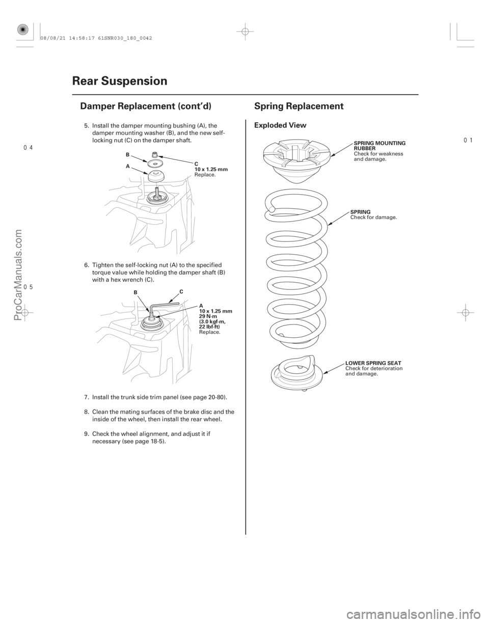
Damper Replacement (cont’d) Spring Replacement
A
B
C
10x1.25mm
B C
A
10x1.25mm
29 N·m
(3.0 kgf·m,
22 lbf·ft) SPRING MOUNTING
RUBBER
SPRING
LOWER SPRING SEAT
5. Install the damper mounting bushing (A), the damper mounting washer (B), and the new self-
locking nut (C) on the damper shaft.
6. Tighten the self-locking nut (A) to the specified torque value while holding the damper shaft (B)
with a hex wrench (C).
7. Install the trunk side trim panel (see page 20-80).
8. Clean the mating surfaces of the brake disc and the inside of the wheel, then install the rear wheel.
9. Check the wheel alignment, and adjust it if necessary (see page 18-5).
Replace.
Replace. Check for weakness
and damage.
Check for damage.
Check for deterioration
and damage.
08/08/21 14:58:17 61SNR030_180_0042
ProCarManuals.com
DYNOMITE -2009-
Page 1454 of 2893
����
�������
�(�#�'���������������
���������������
� �����)����
Exploded View
18-4218-42 Rear Suspension
Damper Replacement (cont’d) Spring Replacement
A
B
C
10x1.25mm
B C
A
10x1.25mm
29 N·m
(3.0 kgf·m,
22 lbf·ft) SPRING MOUNTING
RUBBER
SPRING
LOWER SPRING SEAT
5. Install the damper mounting bushing (A), the damper mounting washer (B), and the new self-
locking nut (C) on the damper shaft.
6. Tighten the self-locking nut (A) to the specified torque value while holding the damper shaft (B)
with a hex wrench (C).
7. Install the trunk side trim panel (see page 20-80).
8. Clean the mating surfaces of the brake disc and the inside of the wheel, then install the rear wheel.
9. Check the wheel alignment, and adjust it if necessary (see page 18-5).
Replace.
Replace. Check for weakness
and damage.
Check for damage.
Check for deterioration
and damage.
08/08/21 14:58:17 61SNR030_180_0042
ProCarManuals.com
DYNOMITE -2009-
Page 1463 of 2893
, connect the
HDS (Honda Diagnostic System) to the data link
connector (DLC) (A) located under the driv")
��������
How to Retrieve DTCs
How to Clear DTCs
18-51
A A
1. With the ignition switch in LOCK (0), connect the
HDS (Honda Diagnostic System) to the data link
connector (DLC) (A) located under the driver’s side
of the dashboard.
2. Turn the ignition switch to ON (II).
3. Make sure the HDS communicates with the vehicle and the TPMS control unit. If it doesn’t,
troubleshoot the DLC circuit (see page 11- 204).
4. Follow the prompts on the HDS to display the DTC(s) on the screen. After determining the DTC,
refer to the DTC troubleshooting.
NOTE: See the HDS Help menu for specific
instructions.
5. Turn the ignition switch to LOCK (0). 1. With the ignition switch in LOCK (0), connect the
HDS to the data link connector (DLC) (A) located
under the driver’s side of the dashboard.
2. Turn the ignition switch to ON (II).
3. Make sure the HDS communicates with the vehicle and the TPMS control unit. If it doesn’t,
troubleshoot the DLC circuit (see page 11-204).
4. Clear the DTC(s) by following the screen prompts on the HDS.
NOTE: See the HDS Help menu for specific
instructions.
5. Turn the ignition switch to LOCK (0).
08/08/21 14:58:22 61SNR030_180_0051
ProCarManuals.com
DYNOMITE -2009-
Page 1464 of 2893
����
Special Tools Required
18-52
TPMS
Memorizing the Tire Pressure Sensor ID
A
TPMS tool J-48714
TPMS tool J-48714
Bartech Wheel")
�Ì�Ï
���
����
����
�(�#�'���������������
�����
���������
�!�����)����
Special Tools Required
18-52
TPMS
Memorizing the Tire Pressure Sensor ID
A
TPMS tool J-48714
TPMS tool J-48714
Bartech Wheelrite Tech300 TPMS tool J-48714
Available through Honda Canada Inc. Technical Tools
Department; Fax 866-398-8665/
e-mail: ch_technicaltools ch.honda.com
All four tire pressure sensor IDs must be memorized to
the TPMS control unit whenever you do any of these
actions: Replace the TPMS control unit.
Replace the tire pressure sensor.
Substitute a known-good wheel with tire pressure sensor.
NOTE: To ensure the control unit memorizes the correct ID, the vehicle with the new sensor must be at least 3 m
(10 ft) away from other vehicles that have tire
pressure sensors.
When doing a tire rotation, memorizing the sensors in not needed.
1. With the ignition switch in LOCK (0), connect the HDS to the data link connector (DLC) (A) located
under the driver’s side of the dashboard.
2. Turn the ignition switch to ON (II).
3. Make sure the HDS communicates with the vehicle and the TPMS control unit. If it doesn’t,
troubleshoot the DLC circuit (see page 11- 204).
4. Select Sensor ID Learning from the mode menu on the HDS. 5. Turn on the TPMS tool by pressing the green select
button. Press the green select button until the
proper light sequence is illuminated as per the tool
user’s manual.
6. Hold the TPMS tool near one wheel, memorize the tire pressure sensor ID by following the screen
prompts on the HDS.
NOTE: If you turn the ignition switch to LOCK (0) before memorizing all four sensor IDs, the memorizing
ID is canceled.
See the HDS Help menu for specific instructions.
7. Repeat step 6 for each wheel until all four sensor IDs are memorized. When all four IDs are
memorized, the low tire pressure indicator blinks.
08/08/21 14:58:23 61SNR030_180_0052
ProCarManuals.com
DYNOMITE -2009-
Page 1465 of 2893
���� Special Tools Required
18-5318-53
Tire Pressure Sensor Location
A
8. Turn the ignition switch to LOCK (0).
9. Disconnect the HDS from the")
�Ì�Ï
���
�(�#�'���������������
�����
�����������"�����)���� Special Tools Required
18-5318-53
Tire Pressure Sensor Location
A
8. Turn the ignition switch to LOCK (0).
9. Disconnect the HDS from the DLC.
10. Test-drive the vehicle at 45 km/h (28 mph) or more for at least 1 minute.
11. Make sure the low tire pressure indicator does not blink.
12. Make sure the tires are inflated to the specified tire pressure listed on the doorjamb sticker.
13. Turn the ignition switch to LOCK (0). Bartech Wheelrite Tech300 TPMS tool J-48714
Available through Honda Canada Inc. Technical Tools
Department; Fax 866-398-8665/
e-mail: ch_technicaltools ch.honda.com
NOTE:
This procedure locates where the tire pressure sensors 1, 2, 3, 4 are mounted, when activated by the
TPMS sensor initializer tool.
Position the vehicle at least 3 m (10 ft) away from other vehicles that have tire pressure sensors.
1. With the ignition switch in LOCK (0), connect the HDS to the data link connector (DLC) (A) located
under the driver’s side of the dashboard.
2. Turn the ignition switch to ON (II).
3. Make sure the HDS communicates with the vehicle and the TPMS control unit. If it doesn’t,
troubleshoot the DLC circuit (see page 11-204).
4. Select Function Test from the mode menu, then select Sensor Position Check on the HDS.
(cont’d)
08/08/21 14:58:23 61SNR030_180_0053
ProCarManuals.com
DYNOMITE -2009-