Page 1241 of 2893
����
14-319
Secondary Shaft Disassembly, Inspection, and Reassembly
CONICAL
SPRING
WASHER
THRUST NEEDLE
BEARING
1ST GEAR TRANSMISSION
HOUSING BEARI")
����
�(�#�'�������
���
�����
�
�������������"�����)����
14-319
Secondary Shaft Disassembly, Inspection, and Reassembly
CONICAL
SPRING
WASHER
THRUST NEEDLE
BEARING
1ST GEAR TRANSMISSION
HOUSING BEARING
1ST/3RD CLUTCH O-RINGS THRUST WASHER,
40 x 51.5 mm
THRUST NEEDLE BEARING
2ND GEAR
NEEDLE BEARINGTHRUST NEEDLE BEARING IDLER GEAR
THRUST NEEDLE BEARING
SEALING RINGS,
29 mm
SET RING 3RD GEAR
SECONDARY SHAFT
THRUST NEEDLE
BEARING
NEEDLE BEARING
THRUST NEEDLE
BEARING
THRUST WASHER,
37x58mm
O-RINGS
2ND CLUTCH NEEDLE BEARING
3RD GEAR COLLAR
LOCKNUT (FLANGE NUT)
24x1.25mm
Left-hand threads
1. Inspect the thrust needle bearing and the needle bearing for galling and r
ough movement.
2. Inspect the splines for excessive wear and damage.
3. Check the shaft bearing surface for scoring and excessive wear.
4. Before installing new O-rings, wrap the shaft splines with tape to prevent O-ring damage.
5. Lubricate all parts with ATF during assembly.
6. Install the conical spring washer and the idler gear in the direction shown.
7. Replace the locknut and the conical spring washer with new ones when assembling the transmission. The locknut has left-hand threads.
8. Check the clearance of 2nd gear (see page 14-321) and 1st gear (see page 14-322).
Replace.
Replace. Selective part
Replace.
Replace. Selective part
Replace. Replace.
08/08/21 14:51:22 61SNR030_140_0321
ProCarManuals.com
DYNOMITE -2009-
Page 1246 of 2893
����
����
���
�µ�µ
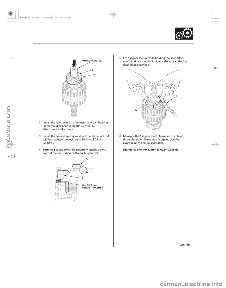
Standard: 0.04 0.12 mm (0.002 0.005 in.)
14-323
07QAD-P0A0100
JI
A
B 40 x 51.5 mm
THRUST WASHER A
B
2. Install the idler gear (I), then install the ball bearing
(J) on the idler gear using the 42 mm I.D.
attachment and a press.
3. Install the conical spring washer (K) and the locknut (L), then tighten the locknut to 29 N·m (3.0 kgf·m,
22 lbf·ft).
4. Turn the secondary shaft assembly upside down, and set the dial indicator (A) on 1st gear (B). 5. Lift 1st gear (A) up while holding the secondary
shaft, and use the dial indicator (B) to read the 1st
gear axial clearance.
6. Measure the 1st gear axial clearance in at least three places while moving 1st gear. Use the
average as the actual clearance.
(cont’d)
08/08/21 14:51:25 61SNR030_140_0325
ProCarManuals.com
DYNOMITE -2009-
Page 1269 of 2893
����
Exploded View
14-344Transmission Housing
Shaft Assembly and Housing Installation
TRANSMISSION HOUSING
MOUNTING BOLTS
10 x 1.25 mm
44 N·m(4.5")
����
�(�#�'�������
���
�����
�������������
� �����)����
Exploded View
14-344Transmission Housing
Shaft Assembly and Housing Installation
TRANSMISSION HOUSING
MOUNTING BOLTS
10 x 1.25 mm
44 N·m(4.5 kgf·m, 33 lbf·ft)
19 Bolts
REVERSE
SHIFT FORK
SECONDARY
SHAFT
SUBASSEMBLY DIFFERENTIAL
ASSEMBLY TRANSMISSION
HANGER
MAINSHAFT
SUBASSEMBLY
NEEDLE
BEARING
REVERSE
SELECTOR
6x1.0mm
14 N·m
(1.4 kgf·m, 10 lbf·ft)
COUNTERSHAFT
REVERSE GEAR
COUNTERSHAFT
SUBASSEMBLY ATF FEED PIPE
ATF LUBRICATION PIPE
SHIFT SOLENOID
VALVE COVER
SELECTOR
CONTROL
SHAFT BAFFLE
PLATE
LOCK WASHER
TRANSMISSION
HOUSING
6x1.0mm
12 N·m
(1.2 kgf·m,
8.7 lbf·ft)
INPUT SHAFT
(MAINSHAFT)
SPEED SENSOR
OUTPUT SHAFT
(COUNTERSHAFT)
SPEED SENSOR
DETENT
SPRING
6x1.0mm
12 N·m
(1.2 kgf·m, 8.7 lbf·ft) 6x1.0mm
12 N·m
(1.2 kgf·m,
8.7 lbf·ft)
O-RING SHIFT
SOLENOID
WIRE
HARNESS
O-RING
O-RING6x1.0mm
12 N·m
(1.2 kgf·m,
8.7 lbf·ft) 6x1.0mm
12 N·m
(1.2 kgf·m,
8.7 lbf·ft)
Replace.
Replace.
Replace.
Replace.
08/08/21 14:52:30 61SNR030_140_0346
ProCarManuals.com
DYNOMITE -2009-
Page 1270 of 2893

B A
C E
F
D
NOTE: Refer to the Exploded View as needed during the
following procedure.
1. Install the differential assembly in the")
���������
14-345
A
B
C
D 6x1.0mm
12 N·m (1.2 kgf·m, 8.7 lbf·ft)
B A
C E
F
D
NOTE: Refer to the Exploded View as needed during the
following procedure.
1. Install the differential assembly in the torque converter housing.
2. Install the baffle plate on the servo body (see step 9 on page 14-343).
3. Assemble the mainshaft, the countershaft, and the secondary shaft.
4. Join the mainshaft subassembly (A), the countershaft subassembly (B), and the secondary
shaft subassembly (C) together. Then install them
in the torque converter housing. Do not bump the
countershaft on the baffle plate (D).
5. Make sure if the countershaft and the differential are clear of the baffle plate. 6. If the detent arm was removed, install the detent
arm (A) with the arm collar (B) on the servo body
(C), and install a new lock washer (D) by aligning its
cutout (E) with the projection (F) of the servo body.
Install and tighten the bolt, then bend the lock tab
of the lock washer against the bolt head.
(cont’d)
Replace.
08/08/21 14:52:31 61SNR030_140_0347
ProCarManuals.com
DYNOMITE -2009-
Page 1271 of 2893

A
B C
B
A D
C
6x1.0mm
14 N·m
(1.4 kgf·m, 10 lbf·ft) B
A
E
7. Install the selector control shaft (A) in")
����
���������
14-346Transmission Housing
Shaft Assembly and Housing Installation (cont’d)
A
B C
B
A D
C
6x1.0mm
14 N·m
(1.4 kgf·m, 10 lbf·ft) B
A
E
7. Install the selector control shaft (A) in the torque
converter housing aligning the manual valve l ever
pin (B) on the selector control shaft with the guide
of the manual valve (C). Pull the manual valve
gently when aligning the manual valve with the
selector control shaft.
8. Hook the detent spring (A) to the detent arm (B). 9. Turn the shift fork shaft (A) so the large chamfered
hole (B) is facing the fork bolt hole (C) of the
reverse shift fork (D).
10. Install the reverse shift fork and the reverse selector together on the shift fork shaft and the
countershaft. Secure the reverse shift fork to the
shift fork shaft with the lock bolt and a new lock
washer (E), then bend the lock tab of the lock
washer against the bolt head.
11. Install the needle bearing and the countershaft reverse gear on the c ountershaft.
12. Install the reverse idler gear in the transmission housing (see page 14-299), if it was removed.
13. Install the idler gear shaft (see page 14-324), if it was removed.
Replace.
08/08/21 14:52:31 61SNR030_140_0348
ProCarManuals.com
DYNOMITE -2009-
Page 1274 of 2893
����
�(�#�'�������
���
�����
�������������
� �����)����
Exploded View
14-349
Transmission End Cover
End Cover Installation
A/T CLUTCH PRESSURE
CONTROL SOLENOID
VALVES B and C
TRANSMISSION RANGE
SWITCH COVER
TRANSMISSION
RANGE SWITCH 6x1.0mm
6x1.0mm
28 N·m
(2.9 kgf·m, 21 lbf·ft)
6x1.0mm
TRANSMISSION
END COVER
6x1.0mm
12 Bolts
28 N·m
(2.9 kgf·m, 21 lbf·ft)CONICAL SPRING
WASHERS
PARK GEAR
STOP SHAFT PARK
LEVER STOP
LOCK WASHER
14 N·m
(1.4 kgf·m,
10 lbf·ft)
PARK PAWL
PARK PAWL
SPRING PARK PAWL
SHAFT
PARK LEVER
SPRING MAINSHAFT
IDLER GEAR
TRANSMISSION
END COVER GASKET HARNESS CLAMP
BRACKETS
6x1.0mm
ATF JOINT
PIPES
ATF JOINT PIPES
ATF PIPE 6x1.0mm
A/T CLUTCH PRESSURE
CONTROL SOLENOID
VALVE A
Torque Specifications
6 x 1.0 mm: 12 N·m (1.2 kgf·m, 8.7 lbf·ft)
28 N·m
(2.9 kgf·m,
21 lbf·ft)
PARK
LEVER
(cont’d)
Replace.
Replace. Replace.
08/08/21 14:52:34 61SNR030_140_0351
ProCarManuals.com
DYNOMITE -2009-
Page 1275 of 2893

07GAB-PF50101
B
C
A
D J
K
G
F
E
A
B
D
6x1.0mm
14 N·m
(1.4 kgf·m,
10 lbf·ft) C H
I
Mainshaft h")
��������� ����
Special Tools Required
14-350 Transmission End Cover
End Cover Installation (cont’d)
07GAB-PF50101
B
C
A
D J
K
G
F
E
A
B
D
6x1.0mm
14 N·m
(1.4 kgf·m,
10 lbf·ft) C H
I
Mainshaft holder 07GAB-PF50101
1. Install the mainshaft holder onto the mainshaft.
2. Lubricate the following parts with ATF: Splines and threads of the mainshaft.
Splines of the mainshaft idler gear.
Old conical spring washer and old locknut.
3. Install the mainshaft idler gear (A), the old conical spring washer (B), and the old locknut (C) on the
mainshaft (D), and tighten the locknut to 226 N·m
(23.0 kgf·m, 166 lbf·ft).
NOTE: Do not tap the idler gear to install.
Use a torque wrench to tighten the locknut. Do not use an impact wrench. 4. Install the park lever (A) and the park lever stop (B)
on the selector control shaft (C), then install the
lock bolt with a new lock washer (D). Do not bend
the lock tab of the lock washer until step 18.
5. Install the park pawl shaft (E), the park pawl spring (F), the park pawl (G), and the stop shaft (H) on the
transmission housing.
6. Lubricate the following parts with ATF: Threads and splines of the countershaft.
Old conical spring washer and old locknut.
Areas where the park gear contacts the conicalspring washer.
7. Install the park gear (I), the old conical spring washer (J), and the old locknut (K) on the
countershaft.
8. Lift the park pawl up, and engage it with the park gear, then tighten the locknut to 226 N·m
(23.0 kgf·m, 166 lbf·ft).
NOTE: Do not tap the park gear to install.
Use a torque wrench to tighten the locknut. Do not use an impact wrench.
Countershaft locknut has left-hand threads.
9. Remove the locknuts and the conical spring washers from the mainshaft and the countershaft.
08/08/21 14:52:35 61SNR030_140_0352
ProCarManuals.com
DYNOMITE -2009-
Page 1276 of 2893

C
B A
6x1.0mm
14 N·m
(1.4 kgf·m,
10 lbf·ft) A
D
E
B
C
F
10. Lubricate the threads of the shafts, new lock")
�µ�µ
�����
���
�����
����
14-351
A
B
D
C
AB 6x1.0mm
14 N·m
(1.4 kgf·m, 10 lbf·ft)
C
B A
6x1.0mm
14 N·m
(1.4 kgf·m,
10 lbf·ft) A
D
E
B
C
F
10. Lubricate the threads of the shafts, new locknuts and new conical spring washers with ATF.
11. Install new conical spring washers (A) with facing stamped mark side up in the direction shown, and
install a new mainshaft locknut (B), a new
countershaft locknut (C), and a new secondary
shaft locknut (D).
12. Tighten the locknuts to 167 N·m (17.0 kgf·m, 123 lbf·ft).
NOTE: Be sure to install the conical spring washers in the direction shown.
Use a torque wrench to tighten the locknut. Do not use an impact wrench.
Countershaft and secondary shaft locknuts have left-hand threads.
13. Remove the mainshaft holder from the mainshaft.
14. Stake the locknuts into the shafts to a depth (A) of 0.7 1.3 mm (0.03 0.05 in.) using a 3.5 mm punch
(B). 15. Install the control lever (A) on the selector control
shaft (B), and install the bolt with a new lock
washer (C), then bend the lock tab of the lock
washer against the bolt head.
16. Set the park lever in the P position, then check that the park pawl (A) engages the park gear (B).
17. If the park pawl does not engage fully, check the distance (C) between the pawl shaft (D) and the
park lever roller pin (E) (see page 14-292).
18. Tighten the lock bolt, and bend the lock tab of the lock washer (F) against the bolt head.
(cont’d)
Replace.
Replace.
Left-hand threads
Replace.
Left-hand threads
Replace.
Replace.
08/08/21 14:52:36 61SNR030_140_0353
ProCarManuals.com
DYNOMITE -2009-